tow YAMAHA WR 250F 2007 Owners Manual
[x] Cancel search | Manufacturer: YAMAHA, Model Year: 2007, Model line: WR 250F, Model: YAMAHA WR 250F 2007Pages: 912, PDF Size: 23.95 MB
Page 54 of 912
1 - 29
GEN
INFO
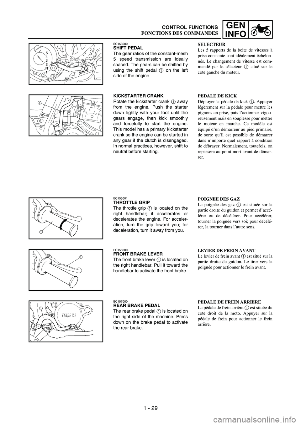
EC153000SHIFT PEDAL
The gear ratios of the constant-mesh
5 speed transmission are ideally
spaced. The gears can be shifted by
using the shift pedal
1 on the left
side of the engine.
KICKSTARTER CRANK
Rotate the kickstarter crank
1 away
from the engine. Push the starter
down lightly with your foot until the
gears engage, then kick smoothly
and forcefully to start the engine.
This model has a primary kickstarter
crank so the engine can be started in
any gear if the clutch is disengaged.
In normal practices, however, shift to
neutral before starting.
1
EC155001THROTTLE GRIP
The throttle grip
1 is located on the
right handlebar; it accelerates or
decelerates the engine. For acceler-
ation, turn the grip toward you; for
deceleration, turn it away from you.
EC156000FRONT BRAKE LEVER
The front brake lever
1 is located on
the right handlebar. Pull it toward the
handlebar to activate the front brake.
EC157000REAR BRAKE PEDAL
The rear brake pedal
1 is located on
the right side of the machine. Press
down on the brake pedal to activate
the rear brake.
SELECTEUR
Les 5 rapports de la boîte de vitesses à
prise constante sont idéalement échelon-
nés. Le changement de vitesse est com-
mandé par le sélecteur 1 situé sur le
côté gauche du moteur.
PEDALE DE KICK
Déployer la pédale de kick 1. Appuyer
légèrement sur la pédale pour mettre les
pignons en prise, puis l’actionner vigou-
reusement mais en souplesse pour mettre
le moteur en marche. Ce modèle est
équipé d’un démarreur au pied primaire,
de sorte qu’il est possible de démarrer
dans n’importe quel rapport à condition
de débrayer. Normalement, toutefois, on
repassera au point mort avant de démar-
rer.
POIGNEE DES GAZ
La poignée des gaz 1 est située sur la
partie droite du guidon et permet d’accé-
lérer ou de décélérer. Pour accélérer,
tourner la poignée vers soi; pour décélé-
rer, la tourner dans l’autre sens.
LEVIER DE FREIN AVANT
Le levier de frein avant 1 est situé sur la
partie droite du guidon. Le tirer vers la
poignée pour actionner le frein avant.
PEDALE DE FREIN ARRIERE
La pédale de frein arrière 1 est située du
côté droit de la moto. Appuyer sur la
pédale de frein pour actionner le frein
arrière.
CONTROL FUNCTIONS
FONCTIONS DES COMMANDES
Page 90 of 912
1 - 65
GEN
INFO
EC1B0000
CLEANING AND
STORAGE
EC1B1000CLEANING
Frequent cleaning of your machine
will enhance its appearance, main-
tain good overall performance, and
extend the life of many components.
1. Before washing the machine,
block off the end of the exhaust
pipe to prevent water from enter-
ing. A plastic bag secured with a
rubber band may be used for this
purpose.
2. If the engine is excessively
greasy, apply some degreaser to
it with a paint brush. Do not
apply degreaser to the chain,
sprockets, or wheel axles.
3. Rinse the dirt and degreaser off
with a garden hose; use only
enough pressure to do the job.
CAUTION:
Excessive hose pressure may
cause water seepage and contami-
nation of wheel bearings, front
forks, brakes and transmission
seals. Many expensive repair bills
have resulted from improper high
pressure detergent applications
such as those available in coin-
operated car washers.
4. After the majority of the dirt has
been hosed off, wash all sur-
faces with warm water and a
mild detergent. Use an old tooth-
brush to clean hard-to-reach
places.
5. Rinse the machine off immedi-
ately with clean water, and dry
all surfaces with a soft towel or
cloth.
6. Immediately after washing,
remove excess water from the
chain with a paper towel and
lubricate the chain to prevent
rust.
7. Clean the seat with a vinyl uphol-
stery cleaner to keep the cover
pliable and glossy.
8. Automotive wax may be applied
to all painted or chromed sur-
faces. Avoid combination
cleaner-waxes, as they may con-
tain abrasives.
9. After completing the above, start
the engine and allow it to idle for
several minutes.
NETTOYAGE ET
REMISAGE
NETTOYAGE
Un nettoyage fréquent de la moto préser-
vera son apparence, maintiendra ses bon-
nes performances et augmentera la durée
de vie de nombre de ses composants.
1. Avant de nettoyer la moto, couvrir
la sortie du tuyau d’échappement
pour éviter toute pénétration d’eau.
Un sachet en plastique retenu par un
élastique fera l’affaire.
2. Si le moteur est fortement encrassé,
appliquer un peu de dégraissant à
l’aide d’un pinceau. Eviter tout con-
tact avec la chaîne, les pignons ou
les axes de roue.
3. Rincer la saleté et le dégraissant au
tuyau d’arrosage, en utilisant juste
la pression nécessaire.
ATTENTION:
Une pression excessive risque de cau-
ser des infiltrations d’eau dans les
roulements des roues, la fourche
avant, les freins et les joints de la
transmission. L’emploi abusif de
détergents sous forte pression, tels que
ceux utilisés dans les portiques de
lavage automatique, est nuisible à la
moto et peut entraîner des réparations
onéreuses.
4. Après avoir éliminé le plus gros de
la saleté au tuyau d’arrosage, laver
toutes les surfaces à l’eau chaude
savonneuse (employer un détergent
doux). Une vieille brosse à dents
convient parfaitement pour nettoyer
les parties difficiles d’accès.
5. Rincer immédiatement la moto à
l’eau claire et sécher toutes les sur-
faces à l’aide d’une peau de cha-
mois, d’une serviette ou d’un
chiffon doux absorbant.
6. Sécher immédiatement la chaîne à
l’aide d’une serviette en papier et la
graisser afin de la protéger contre la
rouille.
7. Nettoyer la selle à l’aide d’un pro-
duit de nettoyage pour similicuir
afin de conserver intacts la sou-
plesse et le lustre de la housse.
8. Une cire pour carrosserie peut être
utilisée pour toutes les surfaces
peintes et chromées. Ne pas
employer de cires détergentes car
elles contiennent souvent des abra-
sifs.
9. Lorsque le nettoyage est terminé,
mettre le moteur en marche et le
laisser tourner au ralenti pendant
plusieurs minutes.
CLEANING AND STORAGE
NETTOYAGE ET REMISAGE
Page 196 of 912

2 - 103
SPECCABLE ROUTING DIAGRAM
ÈInsert the end of the fuel tank breather hose into the hole in the
steering stem.
ÉFasten the throttle cable, hot starter cable and rectifier/regula-
tor lead onto the frame. Locate the clamp end facing the lower
side of the hot starter cable and cut off the tie end.
ÊFasten the diode (at the marking), throttle cable and hot starter
cable onto the frame. Locate the clamp end facing toward the
lower right of the frame and with the tie end facing downward.
ËFasten the wire harness, throttle position sensor lead, starter
motor lead and negative battery lead onto the frame. Pass the
clamp through the hole in the stay (air cut-off valve). Locate the
clamp end facing toward the lower side of the frame and cut off
the tie end.ÌFasten the throttle position sensor lead onto the frame. Locate
the clamp end facing toward the lower side of the frame and
cut off the tie end.
ÍPass the carburetor breather hoses, carburetor overflow hose
and catch tank breather hose between the connecting rod and
cross tube (frame).
ÎFasten the neutral switch lead and oil hose together with the
plastic locking ties and cut off the tie ends.
ÏFasten the neutral switch lead and AC magneto lead onto the
frame. Locate the clamp end facing toward the outside of the
frame and tie end facing toward the rear of the frame.
Page 198 of 912
2 - 105
SPECCABLE ROUTING DIAGRAM
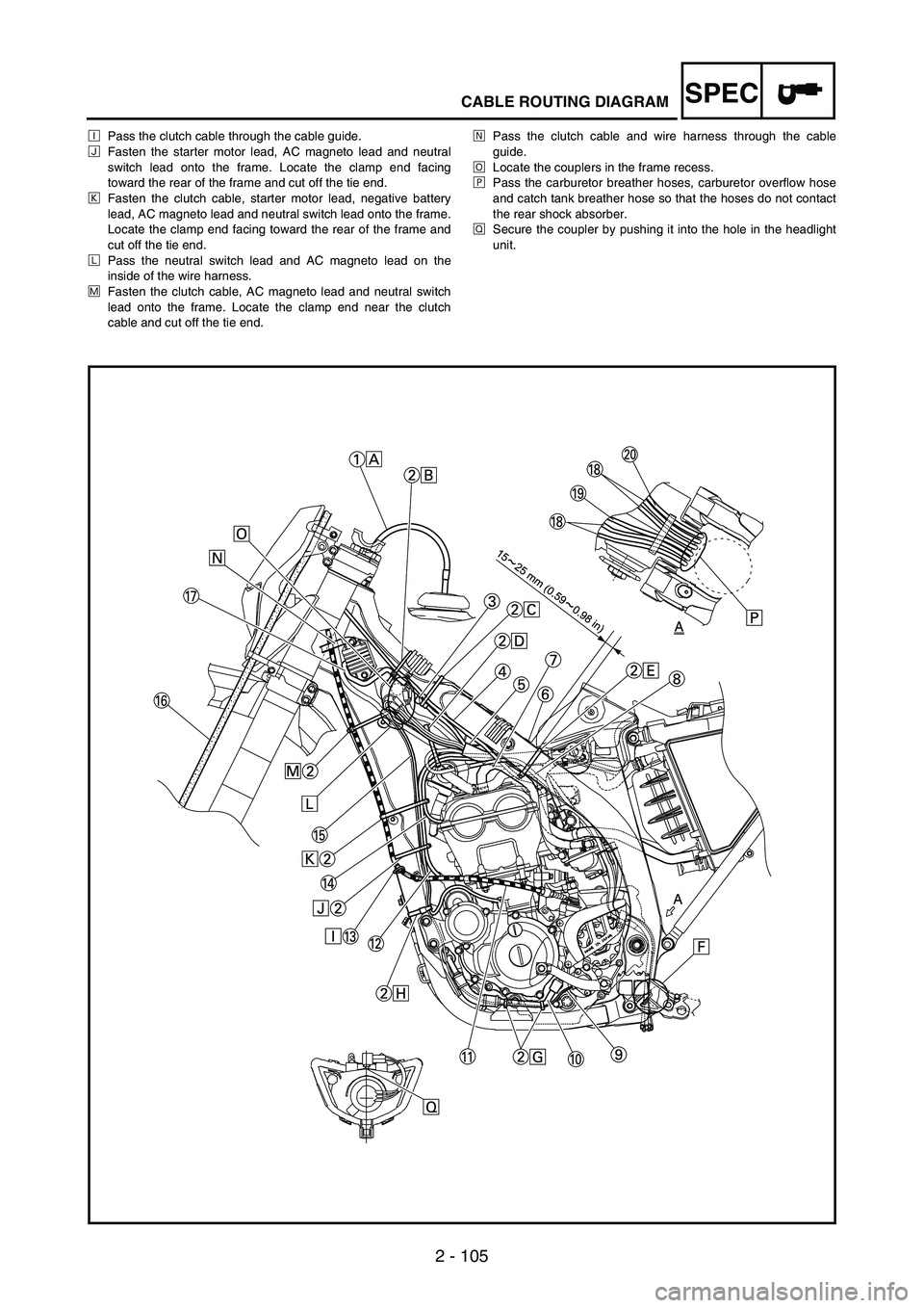
ÐPass the clutch cable through the cable guide.
ÑFasten the starter motor lead, AC magneto lead and neutral
switch lead onto the frame. Locate the clamp end facing
toward the rear of the frame and cut off the tie end.
ÒFasten the clutch cable, starter motor lead, negative battery
lead, AC magneto lead and neutral switch lead onto the frame.
Locate the clamp end facing toward the rear of the frame and
cut off the tie end.
ÓPass the neutral switch lead and AC magneto lead on the
inside of the wire harness.
ÔFasten the clutch cable, AC magneto lead and neutral switch
lead onto the frame. Locate the clamp end near the clutch
cable and cut off the tie end.ÕPass the clutch cable and wire harness through the cable
guide.
ÖLocate the couplers in the frame recess.
×Pass the carburetor breather hoses, carburetor overflow hose
and catch tank breather hose so that the hoses do not contact
the rear shock absorber.
ØSecure the coupler by pushing it into the hole in the headlight
unit.
Page 200 of 912
2 - 107
SPECCABLE ROUTING DIAGRAM
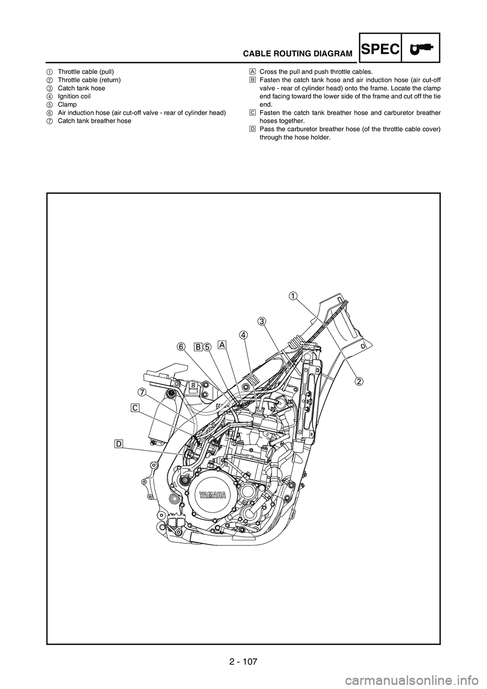
1Throttle cable (pull)
2Throttle cable (return)
3Catch tank hose
4Ignition coil
5Clamp
6Air induction hose (air cut-off valve - rear of cylinder head)
7Catch tank breather hoseÈCross the pull and push throttle cables.
ÉFasten the catch tank hose and air induction hose (air cut-off
valve - rear of cylinder head) onto the frame. Locate the clamp
end facing toward the lower side of the frame and cut off the tie
end.
ÊFasten the catch tank breather hose and carburetor breather
hoses together.
ËPass the carburetor breather hose (of the throttle cable cover)
through the hose holder.
Page 204 of 912

SPEC
2 - 111
CABLE ROUTING DIAGRAM
1Clamp
2Positive battery lead
3Battery
4Negative battery lead
5Taillight coupler
6CDI unit coupler (6-pin)
7CDI unit coupler (3-pin)
8CDI unit coupler (6-pin)ÈFasten the wire harness, negative battery lead and starter
motor lead to the upper engine bracket (left side). Locate the
clamp end facing toward the upper side of the frame with the
tie end cut off on the inside of the frame.
ÉFasten the wire harness, negative battery lead and starter
motor lead to the upper engine bracket (left side). Locate the
clamp end facing toward the upper side of the frame with the
tie end cut off on the inside of the frame. Clamp the wire har-
ness and negative lead at the marking.
ÊPass the starter motor lead through the hole in the relay
holder.
ËFit the cover securely.
ÌConnect the wire harness to the starter relay.
Page 206 of 912

SPEC
2 - 113
CABLE ROUTING DIAGRAM
ÍFasten the catch tank breather hose
and catch tank hose to the rear frame.
Clamp them close to where they are
joined to the frame. Fasten the pipe
tightly enough not to crush it. Locate the
clamp end facing toward the rear of the
frame with the tie end facing downward.
ÎFasten the (three) CDI unit leads and
taillight lead to the rear frame. Locate
the clamp end facing toward the upper
side of the frame and cut off the tie end.
ÏConnect the negative battery lead to
the battery negative terminal.
ÐConnect the negative battery lead to
the wire harness.ÑFasten the wire harness to the rear
frame. Locate the clamp end facing
toward the upper side of the frame and
the tie end toward the inside of the
frame. Clamp the wire harness at the
marking.
ÒPass the wire harness, starter relay
lead, starting circuit cut-off relay lead
and negative battery lead through the
hole in the relay holder.
ÓFasten the (three) CDI unit leads and
taillight lead to the rear frame. Locate
the clamp end facing toward the lower
side of the frame and cut off the tie end.ÔFasten the taillight lead to the rear
frame. Locate the clamp end facing
toward the upper side of the frame and
cut off the time end.
ÕDo not allow the taillight lead to
slacken.
ÖLocate the CDI unit lead between the
CDI unit and rear fender.
×Locate the CDI unit coupler in the clear-
ance between the upper side of the CDI
unit and lower side of the catch tank
stay.
ØLocate the CDI unit lead between the
CDI unit and rear frame.
Page 210 of 912
2 - 117
SPECCABLE ROUTING DIAGRAM
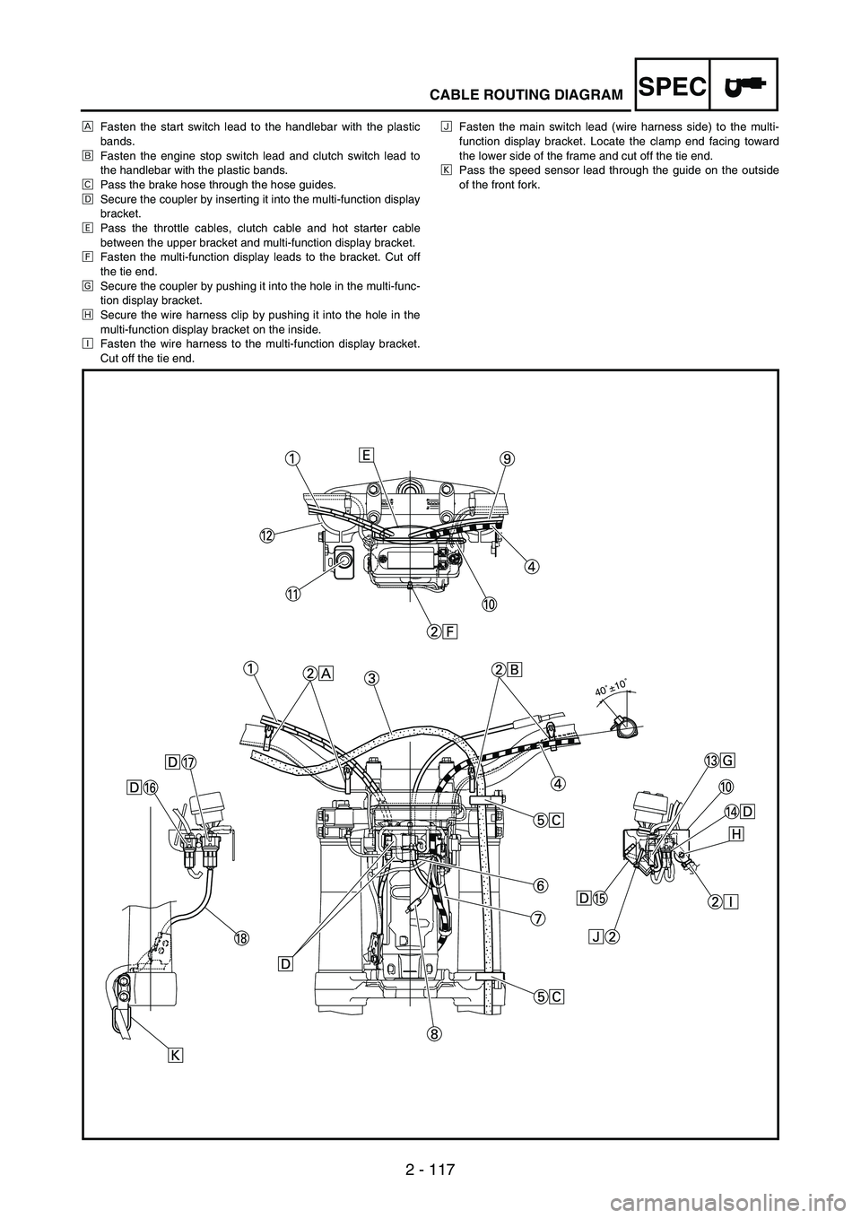
ÈFasten the start switch lead to the handlebar with the plastic
bands.
ÉFasten the engine stop switch lead and clutch switch lead to
the handlebar with the plastic bands.
ÊPass the brake hose through the hose guides.
ËSecure the coupler by inserting it into the multi-function display
bracket.
ÌPass the throttle cables, clutch cable and hot starter cable
between the upper bracket and multi-function display bracket.
ÍFasten the multi-function display leads to the bracket. Cut off
the tie end.
ÎSecure the coupler by pushing it into the hole in the multi-func-
tion display bracket.
ÏSecure the wire harness clip by pushing it into the hole in the
multi-function display bracket on the inside.
ÐFasten the wire harness to the multi-function display bracket.
Cut off the tie end.ÑFasten the main switch lead (wire harness side) to the multi-
function display bracket. Locate the clamp end facing toward
the lower side of the frame and cut off the tie end.
ÒPass the speed sensor lead through the guide on the outside
of the front fork.
40˚±10˚
Page 244 of 912
3 - 33
INSP
ADJ
COOLANT LEVEL INSPECTION
WARNING
Do not remove the radiator cap 1,
drain bolt and hoses when the
engine and radiator are hot. Scald-
ing hot fluid and steam may be
blown out under pressure, which
could cause serious injury.
When the engine has cooled,
place a thick towel over the radia-
tor cap, slowly rotate the cap
counterclockwise to the detent.
This procedure allows any resid-
ual pressure to escape. When the
hissing sound has stopped, press
down on the cap while turning
counterclockwise and remove it.
CAUTION:
Hard water or salt water is harmful
to the engine parts. You may use
distilled water, if you can’t get soft
water.
1. Place the machine on a level
place, and hold it in an upright
position.
2. Remove:
Radiator cap
3. Check:
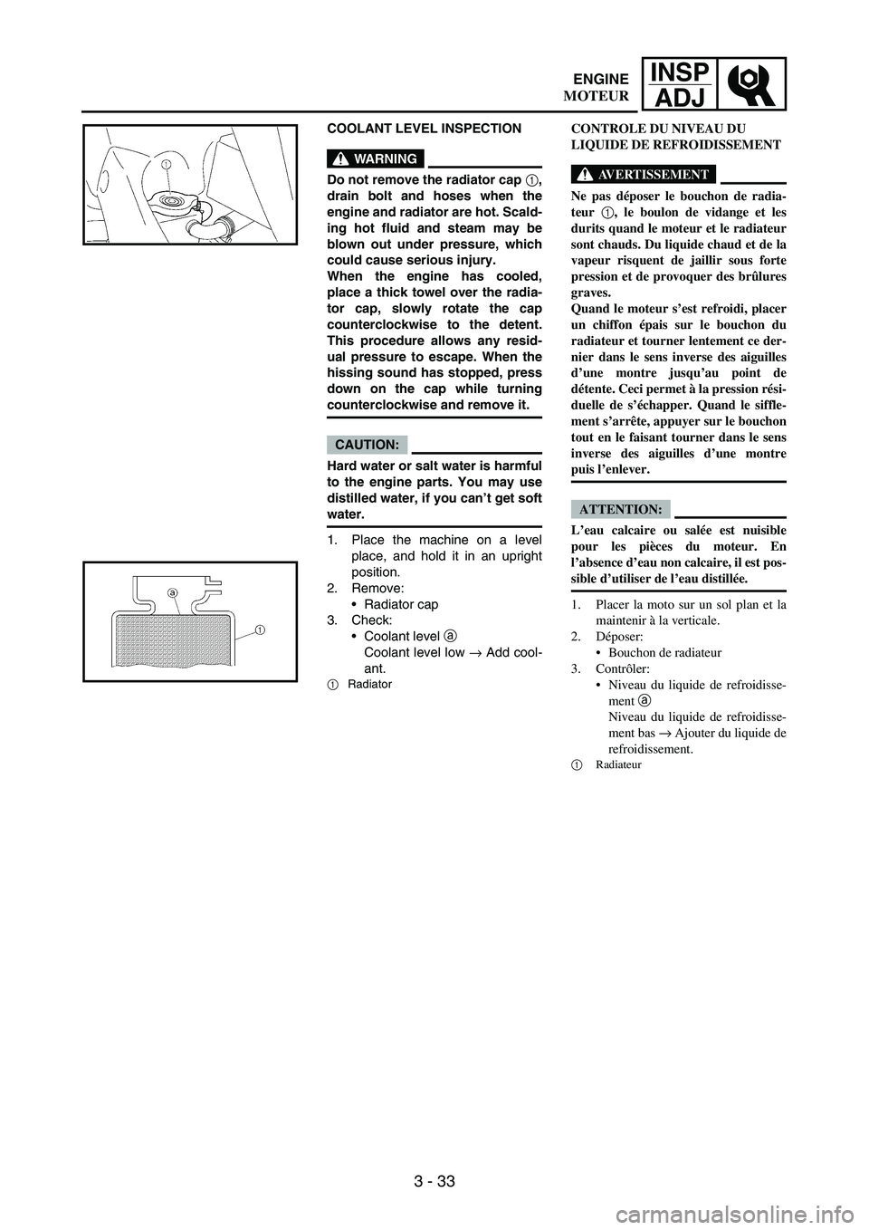
Coolant level
a
Coolant level low
→ Add cool-
ant.
1Radiator
CONTROLE DU NIVEAU DU
LIQUIDE DE REFROIDISSEMENT
AVERTISSEMENT
Ne pas déposer le bouchon de radia-
teur 1, le boulon de vidange et les
durits quand le moteur et le radiateur
sont chauds. Du liquide chaud et de la
vapeur risquent de jaillir sous forte
pression et de provoquer des brûlures
graves.
Quand le moteur s’est refroidi, placer
un chiffon épais sur le bouchon du
radiateur et tourner lentement ce der-
nier dans le sens inverse des aiguilles
d’une montre jusqu’au point de
détente. Ceci permet à la pression rési-
duelle de s’échapper. Quand le siffle-
ment s’arrête, appuyer sur le bouchon
tout en le faisant tourner dans le sens
inverse des aiguilles d’une montre
puis l’enlever.
ATTENTION:
L’eau calcaire ou salée est nuisible
pour les pièces du moteur. En
l’absence d’eau non calcaire, il est pos-
sible d’utiliser de l’eau distillée.
1. Placer la moto sur un sol plan et la
maintenir à la verticale.
2. Déposer:
Bouchon de radiateur
3. Contrôler:
Niveau du liquide de refroidisse-
ment a
Niveau du liquide de refroidisse-
ment bas → Ajouter du liquide de
refroidissement.
1
Radiateur
ENGINE
MOTEUR
Page 288 of 912
3 - 77
INSP
ADJ
EC360000
CHASSIS
EC361012BRAKE SYSTEM AIR BLEEDING
WARNING
Bleed the brake system if:
The system has been disassem-
bled.
A brake hose has been loosened
or removed.
The brake fluid is very low.
The brake operation is faulty.
A dangerous loss of braking per-
formance may occur if the brake
system is not properly bled.
1. Remove:
Brake master cylinder cap
Diaphragm
Reservoir float (front brake)
Protector (rear brake)
2. Bleed:
Brake fluid
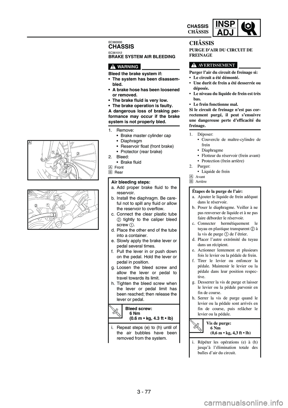
ÈFront
ÉRear
Air bleeding steps:
a. Add proper brake fluid to the
reservoir.
b. Install the diaphragm. Be care-
ful not to spill any fluid or allow
the reservoir to overflow.
c. Connect the clear plastic tube
2 tightly to the caliper bleed
screw
1.
d. Place the other end of the tube
into a container.
e. Slowly apply the brake lever or
pedal several times.
f. Pull the lever in or push down
on the pedal. Hold the lever or
pedal in position.
g. Loosen the bleed screw and
allow the lever or pedal to
travel towards its limit.
h. Tighten the bleed screw when
the lever or pedal limit has
been reached; then release the
lever or pedal.
T R..
Bleed screw:
6 Nm
(0.6 m kg, 4.3 ft lb)
i. Repeat steps (e) to (h) until of
the air bubbles have been
removed from the system.
È
É
CHÂSSIS
PURGE D’AIR DU CIRCUIT DE
FREINAGE
AVERTISSEMENT
Purger l’air du circuit de freinage si:
Le circuit a été démonté.
Une durit de frein a été desserrée ou
déposée.
Le niveau du liquide de frein est très
bas.
Le frein fonctionne mal.
Si le circuit de freinage n’est pas cor-
rectement purgé, il peut s’ensuivre
une dangereuse perte d’efficacité du
freinage.
1. Déposer:
Couvercle de maître-cylindre de
frein
Diaphragme
Flotteur du réservoir (frein avant)
Protection (frein arrière)
2. Purger:
Liquide de frein
È
Avant
É
Arrière
Étapes de la purge de l’air:
a. Ajouter le liquide de frein adéquat
dans le réservoir.
b. Poser le diaphragme. Veiller à ne
pas renverser de liquide et à ne pas
faire déborder le réservoir.
c. Connecter hermétiquement le
tuyau en plastique transparent 2 à
la vis de purge 1 de l’étrier.
d. Placer l’autre extrémité du tuyau
dans un récipient.
e. Actionner lentement et plusieurs
fois le levier ou la pédale de frein.
f. Tirer le levier ou enfoncer la
pédale. Maintenir le levier ou la
pédale dans leur position respec-
tive.
g. Desserrer la vis de purge et laisser
le levier ou la pédale parvenir en
fin de course.
h. Serrer la vis de purge quand le
levier ou la pédale sont arrivés en
fin de course, puis relâcher le
levier ou la pédale.
T R..
Vis de purge:
6 Nm
(0,6 m kg, 4,3 ft lb)
i. Répéter les opérations (e) à (h)
jusqu’à l’élimination totale des
bulles d’air du circuit.
CHASSIS
CHÂSSIS