fuel tank removal YAMAHA WR 250F 2007 Owners Manual
[x] Cancel search | Manufacturer: YAMAHA, Model Year: 2007, Model line: WR 250F, Model: YAMAHA WR 250F 2007Pages: 912, PDF Size: 23.95 MB
Page 232 of 912
INSP
ADJ
3 - 21
EC350000
ENGINE
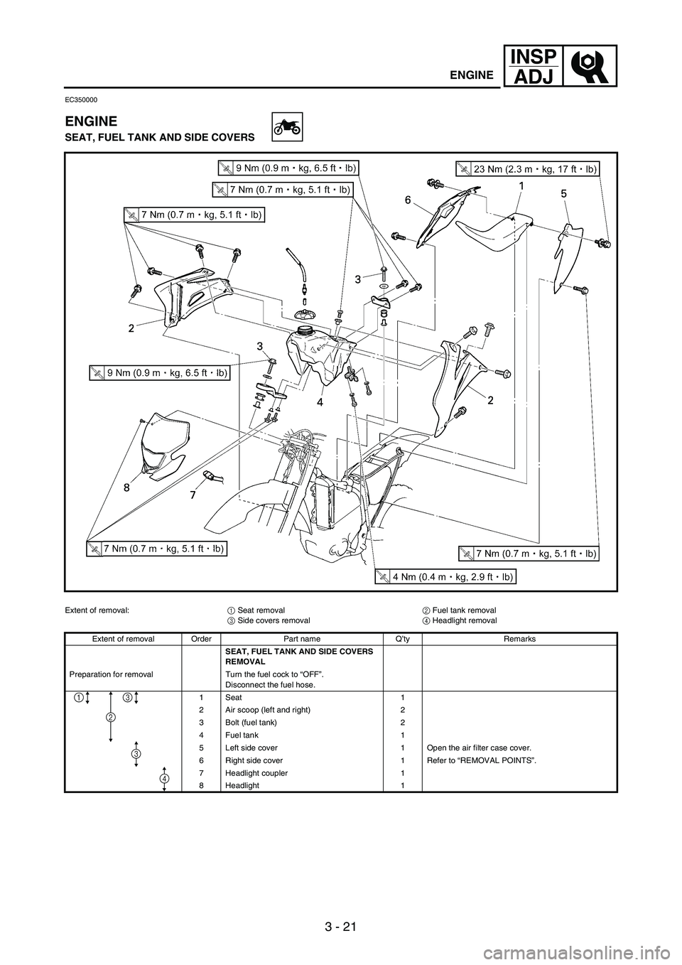
SEAT, FUEL TANK AND SIDE COVERS
Extent of removal:
1 Seat removal
2 Fuel tank removal
3 Side covers removal
4 Headlight removal
Extent of removal Order Part name Q’ty Remarks
SEAT, FUEL TANK AND SIDE COVERS
REMOVAL
Preparation for removal Turn the fuel cock to “OFF”.
Disconnect the fuel hose.
1Seat 1
2 Air scoop (left and right) 2
3 Bolt (fuel tank) 2
4 Fuel tank 1
5 Left side cover 1 Open the air filter case cover.
6 Right side cover 1 Refer to “REMOVAL POINTS”.
7 Headlight coupler 1
8 Headlight 1
2
13
4
3
ENGINE
Page 238 of 912
INSP
ADJ
3 - 27
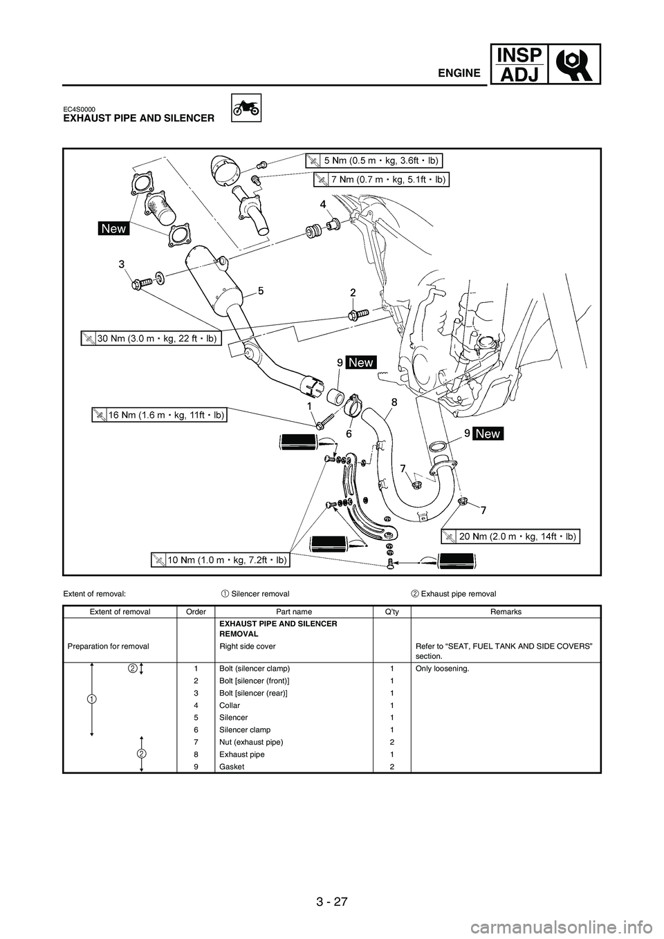
EC4S0000EXHAUST PIPE AND SILENCER
Extent of removal:
1 Silencer removal
2 Exhaust pipe removal
Extent of removal Order Part name Q’ty Remarks
EXHAUST PIPE AND SILENCER
REMOVAL
Preparation for removal Right side cover Refer to “SEAT, FUEL TANK AND SIDE COVERS”
section.
1 Bolt (silencer clamp) 1 Only loosening.
2 Bolt [silencer (front)] 1
3 Bolt [silencer (rear)] 1
4 Collar 1
5 Silencer 1
6 Silencer clamp 1
7 Nut (exhaust pipe) 2
8 Exhaust pipe 1
9 Gasket 2
1
2
2
ENGINE
Page 408 of 912
5 - 1
ENGRADIATOR
ENGINE
EC450001
RADIATOR
NOTE:This section is intended for those who have basic knowledge and skill concerning the
servicing of Yamaha motorcycles (e.g., Yamaha dealers, service engineers, etc.)
Those who have little knowledge and skill concerning servicing are requested not to
undertake inspection, adjustment, disassembly, or reassembly only by reference to
this manual. It may lead to servicing trouble and mechanical damage.
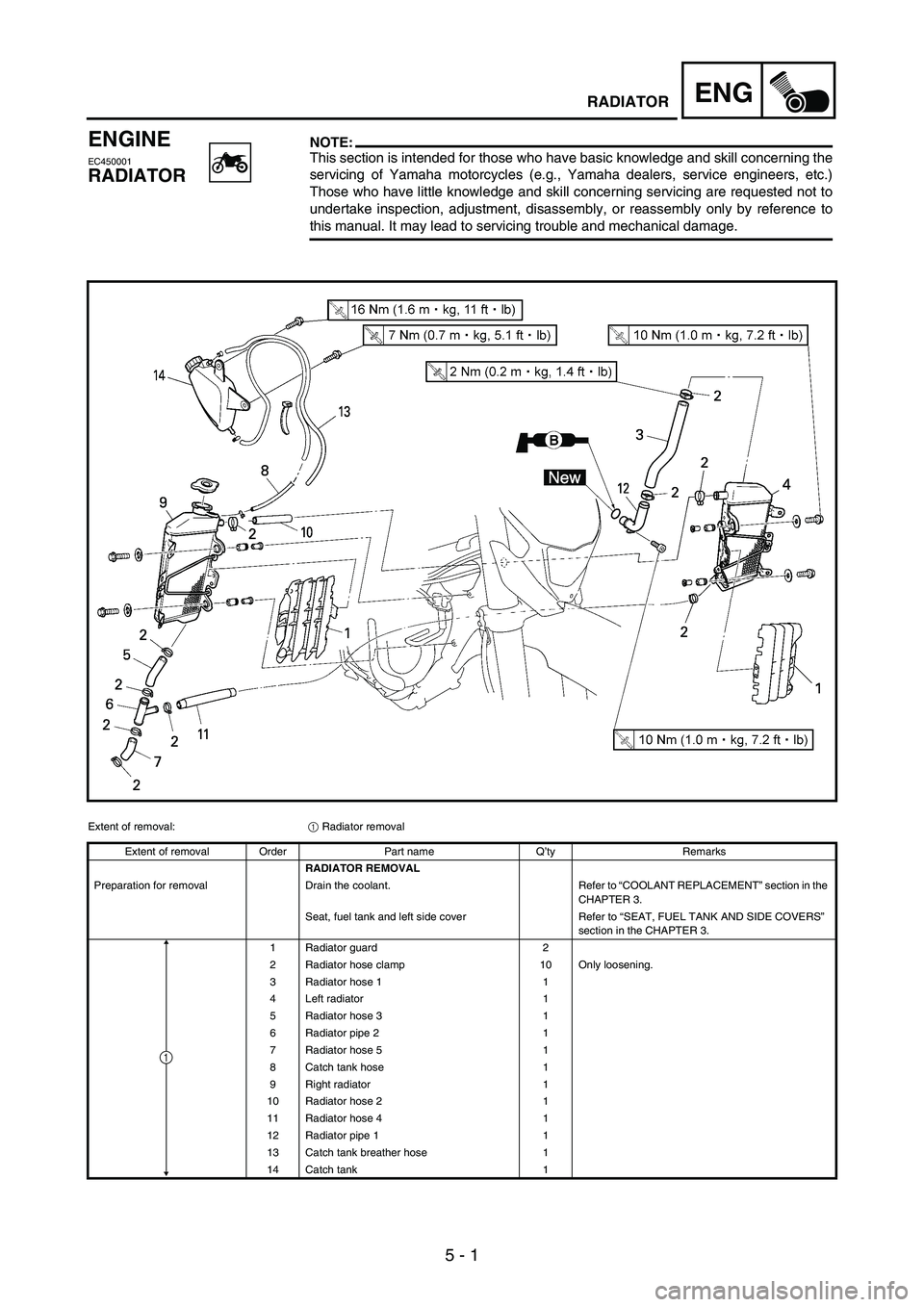
Extent of removal:
1 Radiator removal
Extent of removal Order Part name Q’ty Remarks
RADIATOR REMOVAL
Preparation for removal Drain the coolant. Refer to “COOLANT REPLACEMENT” section in the
CHAPTER 3.
Seat, fuel tank and left side cover Refer to “SEAT, FUEL TANK AND SIDE COVERS”
section in the CHAPTER 3.
1 Radiator guard 2
2 Radiator hose clamp 10 Only loosening.
3 Radiator hose 1 1
4 Left radiator 1
5 Radiator hose 3 1
6 Radiator pipe 2 1
7 Radiator hose 5 1
8 Catch tank hose 1
9 Right radiator 1
10 Radiator hose 2 1
11 Radiator hose 4 1
12 Radiator pipe 1 1
13 Catch tank breather hose 1
14 Catch tank 1
1
Page 416 of 912
5 - 9
ENGCARBURETOR
CARBURETOR
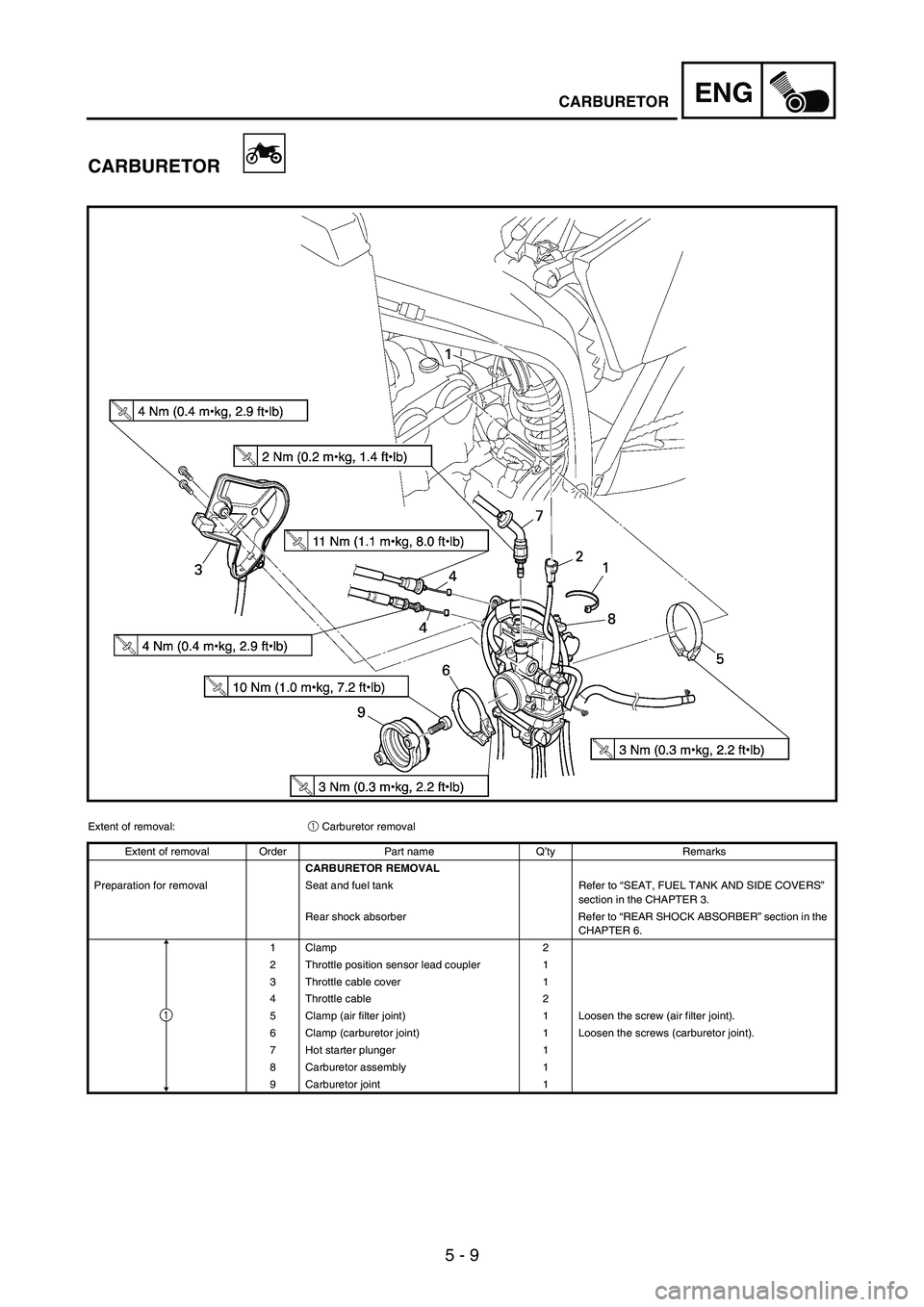
Extent of removal:
1 Carburetor removal
Extent of removal Order Part name Q’ty Remarks
CARBURETOR REMOVAL
Preparation for removal Seat and fuel tank Refer to “SEAT, FUEL TANK AND SIDE COVERS”
section in the CHAPTER 3.
Rear shock absorber Refer to “REAR SHOCK ABSORBER” section in the
CHAPTER 6.
1 Clamp 2
2 Throttle position sensor lead coupler 1
3 Throttle cable cover 1
4 Throttle cable 2
5 Clamp (air filter joint) 1 Loosen the screw (air filter joint).
6 Clamp (carburetor joint) 1 Loosen the screws (carburetor joint).
7 Hot starter plunger 1
8 Carburetor assembly 1
9 Carburetor joint 1
1
Page 452 of 912
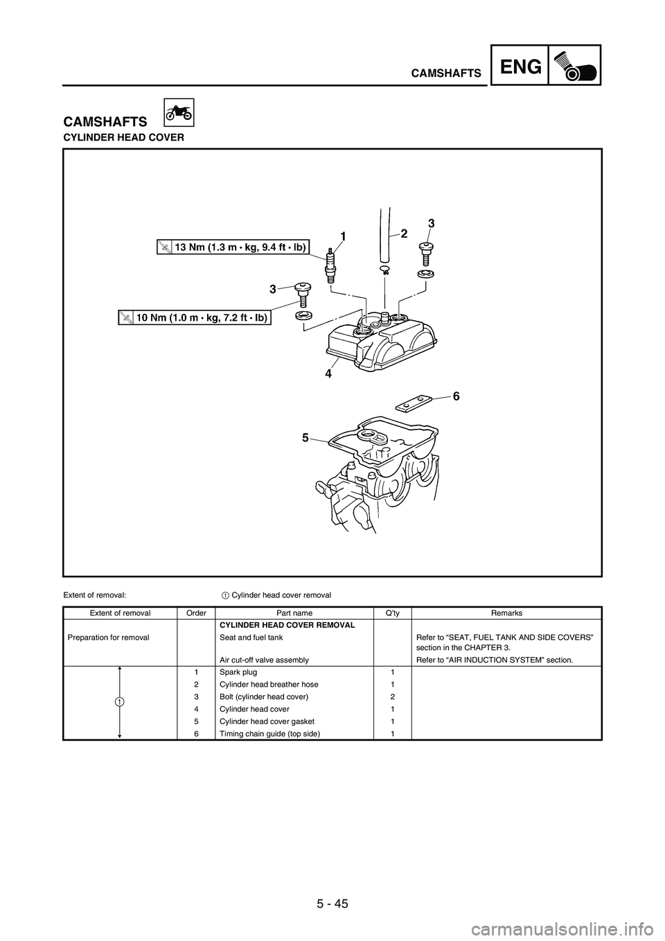
5 - 45
ENGCAMSHAFTS
CAMSHAFTS
CYLINDER HEAD COVER
Extent of removal:
1 Cylinder head cover removal
Extent of removal Order Part name Q’ty Remarks
CYLINDER HEAD COVER REMOVAL
Preparation for removal Seat and fuel tank Refer to “SEAT, FUEL TANK AND SIDE COVERS”
section in the CHAPTER 3.
Air cut-off valve assembly Refer to “AIR INDUCTION SYSTEM” section.
1 Spark plug 1
2 Cylinder head breather hose 1
3 Bolt (cylinder head cover) 2
4 Cylinder head cover 1
5 Cylinder head cover gasket 1
6 Timing chain guide (top side) 1
1
Page 474 of 912
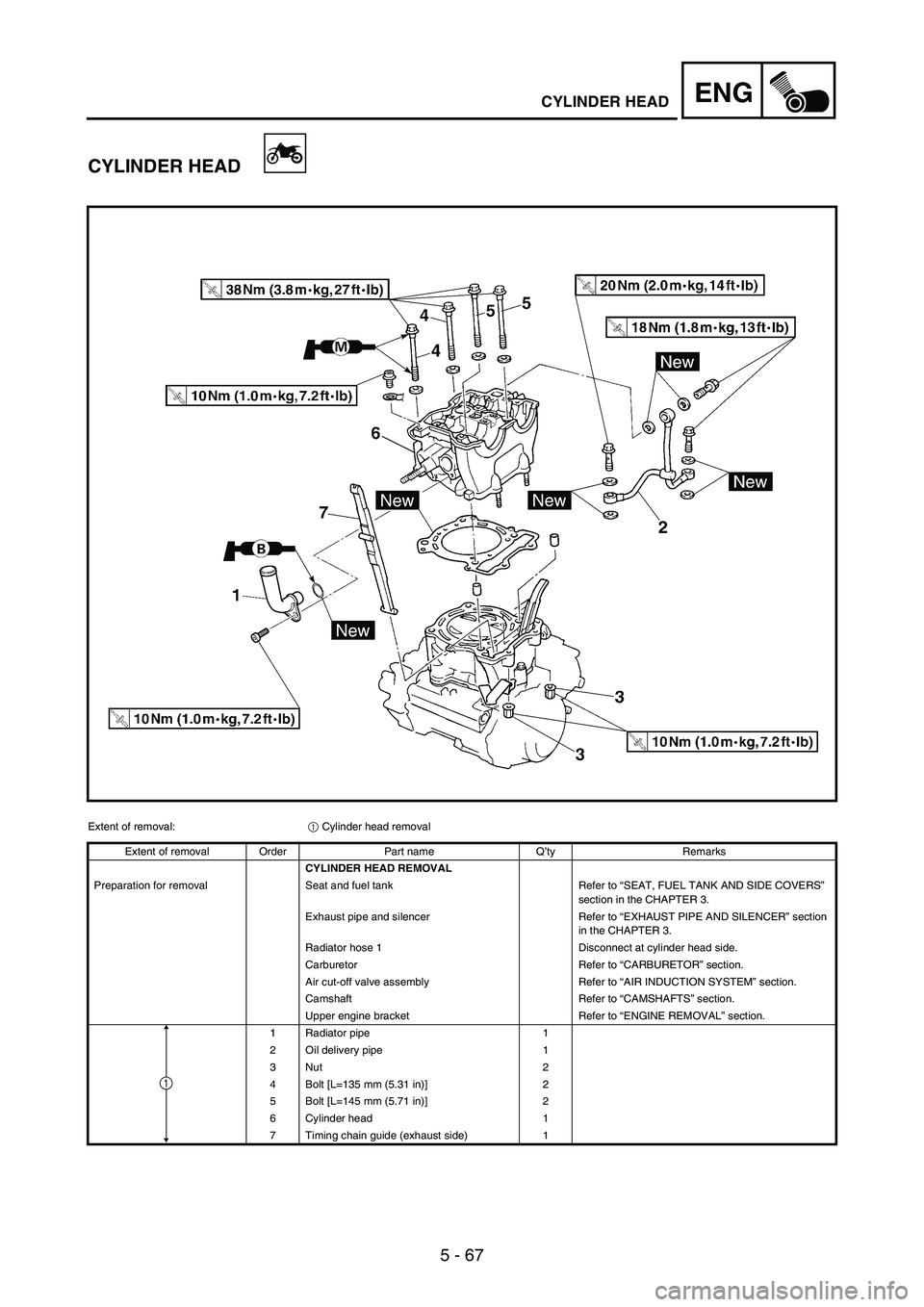
5 - 67
ENGCYLINDER HEAD
CYLINDER HEAD
Extent of removal:
1 Cylinder head removal
Extent of removal Order Part name Q’ty Remarks
CYLINDER HEAD REMOVAL
Preparation for removal Seat and fuel tank Refer to “SEAT, FUEL TANK AND SIDE COVERS”
section in the CHAPTER 3.
Exhaust pipe and silencer Refer to “EXHAUST PIPE AND SILENCER” section
in the CHAPTER 3.
Radiator hose 1 Disconnect at cylinder head side.
Carburetor Refer to “CARBURETOR” section.
Air cut-off valve assembly Refer to “AIR INDUCTION SYSTEM” section.
Camshaft Refer to “CAMSHAFTS” section.
Upper engine bracket Refer to “ENGINE REMOVAL” section.
1 Radiator pipe 1
2 Oil delivery pipe 1
3Nut 2
4 Bolt [L=135 mm (5.31 in)] 2
5 Bolt [L=145 mm (5.71 in)] 2
6 Cylinder head 1
7 Timing chain guide (exhaust side) 1
1
Page 592 of 912
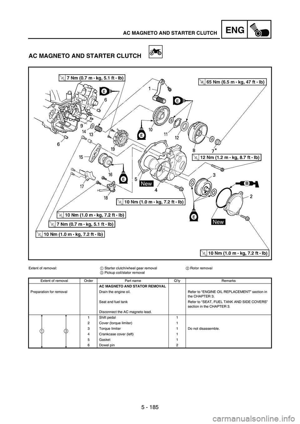
5 - 185
ENGAC MAGNETO AND STARTER CLUTCH
AC MAGNETO AND STARTER CLUTCH
Extent of removal:
1 Starter clutch/wheel gear removal
2 Rotor removal
3 Pickup coil/stator removal
Extent of removal Order Part name Q’ty Remarks
AC MAGNETO AND STATOR REMOVAL
Preparation for removal Drain the engine oil. Refer to “ENGINE OIL REPLACEMENT” section in
the CHAPTER 3.
Seat and fuel tank Refer to “SEAT, FUEL TANK AND SIDE COVERS”
section in the CHAPTER 3.
Disconnect the AC magneto lead.
1 Shift pedal 1
2 Cover (torque limiter) 1
3 Torque limiter 1 Do not disassemble.
4 Crankcase cover (left) 1
5 Gasket 1
6 Dowel pin 2
31
Page 614 of 912
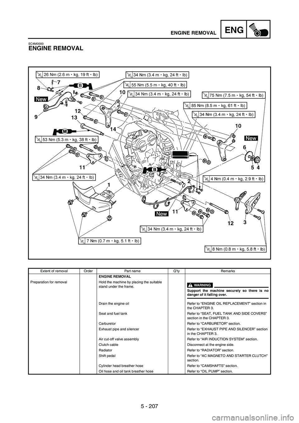
5 - 207
ENGENGINE REMOVAL
EC4M0000
ENGINE REMOVAL
Extent of removal Order Part name Q’ty Remarks
ENGINE REMOVAL
Preparation for removal Hold the machine by placing the suitable
stand under the frame.
WARNING
Support the machine securely so there is nodanger of it falling over.
Drain the engine oil Refer to “ENGINE OIL REPLACEMENT” section in
the CHAPTER 3.
Seat and fuel tank Refer to “SEAT, FUEL TANK AND SIDE COVERS”
section in the CHAPTER 3.
Carburetor Refer to “CARBURETOR” section.
Exhaust pipe and silencer Refer to “EXHAUST PIPE AND SILENCER” section
in the CHAPTER 3.
Air cut-off valve assembly Refer to “AIR INDUCTION SYSTEM” section.
Clutch cable Disconnect at the engine side.
Radiator Refer to “RADIATOR” section.
Shift pedal Refer to “AC MAGNETO AND STARTER CLUTCH”
section.
Cylinder head breather hose Refer to “CAMSHAFTS” section.
Oil hose and oil tank breather hose Refer to “OIL PUMP” section.
Page 804 of 912
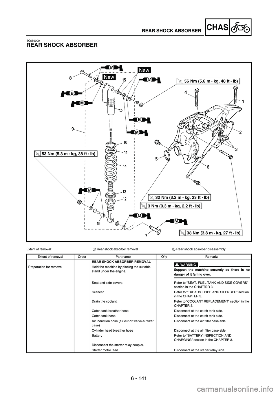
6 - 141
CHASREAR SHOCK ABSORBER
EC580000
REAR SHOCK ABSORBER
Extent of removal:
1 Rear shock absorber removal
2 Rear shock absorber disassembly
Extent of removal Order Part name Q’ty Remarks
REAR SHOCK ABSORBER REMOVAL
WARNING
Support the machine securely so there is nodanger of it falling over. Preparation for removal Hold the machine by placing the suitable
stand under the engine.
Seat and side covers Refer to “SEAT, FUEL TANK AND SIDE COVERS”
section in the CHAPTER 3.
Silencer Refer to “EXHAUST PIPE AND SILENCER” section
in the CHAPTER 3.
Drain the coolant. Refer to “COOLANT REPLACEMENT” section in the
CHAPTER 3.
Catch tank breather hose Disconnect at the catch tank side.
Catch tank hose Disconnect at the catch tank side.
Air induction hose (air cut-off valve-air filter
case)Disconnect at the air filter case side.
Cylinder head breather hose Disconnect at the air filter case side.
Battery Refer to “BATTERY INSPECTION AND
CHARGING” section in the CHAPTER 3.
Disconnect the starter relay coupler.
Starter motor lead Disconnect at the starter relay side.