check engine YAMAHA WR 250F 2007 Owners Manual
[x] Cancel search | Manufacturer: YAMAHA, Model Year: 2007, Model line: WR 250F, Model: YAMAHA WR 250F 2007Pages: 912, PDF Size: 23.95 MB
Page 6 of 912
IMPORTANT NOTICE
THIS MACHINE IS DESIGNED
STRICTLY FOR COMPETITION
USE, ONLY ON A CLOSED
COURSE. It is illegal for this machine
to be operated on any public street,
road, or highway. Off-road use on
public lands may also be illegal.
Please check local regulations
before riding.
1. THIS MACHINE IS TO BE
OPERATED BY AN EXPERI-
ENCED RIDER ONLY.
Do not attempt to operate
this machine at maximum
power until you are totally
familiar with its characteris-
tics.
2. THIS MACHINE IS
DESIGNED TO BE RIDDEN
BY THE OPERATOR ONLY.
Do not carry passengers on
this machine.
3. ALWAYS WEAR PROTEC-
TIVE APPAREL.
When operating this
machine, always wear an
approved helmet with gog-
gles or a face shield. Also
wear heavy boots, gloves,
and protective clothing.
Always wear proper fitting
clothing that will not be
caught in any of the moving
parts or controls of the
machine.
4. ALWAYS MAINTAIN YOUR
MACHINE IN PROPER
WORKING ORDER.
For safety and reliability,
the machine must be prop-
erly maintained. Always
perform the pre-operation
checks indicated in this
manual. Correcting a
mechanical problem before
you ride may prevent an
accident.
5. GASOLINE IS HIGHLY
FLAMMABLE.
Always turn off the engine
while refueling. Take care
to not spill any gasoline on
the engine or exhaust sys-
tem. Never refuel in the
vicinity of an open flame, or
while smoking.
SAFETY INFORMATION
NOTICE
IMPORTANTE
CETTE MACHINE EST STRICTE-
MENT DESTINEE A LA COMPETI-
TION, UNIQUEMENT SUR CIRCUIT
FERME. Il est illégal d’utiliser cette
machine sur une rue, route ou artère
publique. L’utilisation de tous-terrains
sur les domaines publics peut également
être illégale. Prière de vérifier les lois
locales avant de conduire.
1. CETTE MACHINE NE DOIT
ETRE UTILISEE QUE PAR
UN CONDUCTEUR EXPERI-
MENTE.
Ne pas essayer d’utiliser cette
machine à sa puissance maxi-
mum tant que vous n’êtes pas
familier avec ses caractéristi-
ques.
2. CETTE MACHINE N’EST
CONCUE POUR ETRE UTI-
LISEE QUE PAR LE CON-
DUCTEUR.
Ne pas prendre de passagers
sur cette machine.
3. TOUJOURS PORTER UN
EQUIPEMENT DE PROTEC-
TION.
Lors de l’utilisation de cette
machine, toujours porter un
casque homologué avec des
lunettes ou un protège-visage.
Porter également de grosses
bottes, des gants et des vête-
ments de protection. Toujours
porter des vêtements de taille
correcte qui ne seront pas pris
dans une des pièces ou com-
mandes mobiles de la machine.
4. TOUJOURS GARDER
VOTRE MACHINE EN BON
ETAT DE MARCHE.
La machine doit être correcte-
ment entretenue pour des
questions de sécurité et de fia-
bilité. Toujours effectuer les
opérations précédant l’utilisa-
tion indiquées dans ce manuel.
La correction d’un problème
mécanique avant la conduite
peut empêcher un éventuel
accident.
5. L’ESSENCE EST HAUTE-
MENT INFLAMMABLE.
Toujours arrêter le moteur en
faisant le plein. Faire attention
à ne pas verser d’essence sur le
moteur ou le pot d’échappe-
ment. Ne jamais faire le plein
au voisinage d’une flamme une
ou en fumant.
INFORMATION DE SECURITE
Page 20 of 912
E0A0000
CONTENTS
CHAPTER 1
GENERAL
INFORMATION
DESCRIPTION........................... 1-1
MACHINE IDENTIFICATION..... 1-3
IMPORTANT INFORMATION.... 1-5
CHECKING OF
CONNECTION............................ 1-9
SPECIAL TOOLS..................... 1-11
CONTROL FUNCTIONS.......... 1-27
MULTI-FUNCTION DISPLAY... 1-35
FUEL........................................ 1-49
STARTING AND BREAK-IN.... 1-51
TORQUE-CHECK POINTS...... 1-59
CLEANING AND STORAGE.... 1-65
CHAPTER 2
SPECIFICATIONS
GENERAL SPECIFICATIONS... 2-1
MAINTENANCE
SPECIFICATIONS...................... 2-4
GENERAL TORQUE
SPECIFICATIONS.................... 2-19
DEFINITION OF UNITS............ 2-19
LUBRICATION DIAGRAMS..... 2-97
CABLE ROUTING
DIAGRAM............................... 2-101
CHAPTER 3
REGULAR
INSPECTION AND
ADJUSTMENTS
MAINTENANCE INTERVALS.... 3-1
PRE-OPERATION
INSPECTION AND
MAINTENANCE....................... 3-16
ENGINE.................................... 3-21
CHASSIS.................................. 3-77
ELECTRICAL......................... 3-121
TABLES DES
MATIERES
CHAPITRE 1
RENSEIGNEMENTS
GENERAUX
DESCRIPTION................................ 1-1
IDENTIFICATION DE
LA MOTO........................................ 1-3
INFORMATIONS
IMPORTANTES.............................. 1-5
VERIFICATION DES
CONNEXIONS................................ 1-9
OUTILS SPECIAUX..................... 1-14
FONCTIONS DES
COMMANDES.............................. 1-27
ECRAN MULTIFONCTION....... 1-35
CARBURANT................................ 1-49
MISE EN MARCHE ET
RODAGE........................................ 1-51
POINTS DE VERIFICATION
DES COUPLES DE
SERRAGE...................................... 1-60
NETTOYAGE ET REMISAGE... 1-65
CHAPITRE 2
CARACTERISTIQUES
CARACTERISTIQUES
GENERALES................................. 2-20
CARACTERISTIQUES
D’ENTRETIEN.............................. 2-23
CARACTERISTIQUES
GENERALES DE COUPLE......... 2-38
DEFINITION DES UNITES......... 2-38
DIAGRAMMES DE
LUBRIFICATION......................... 2-98
DIAGRAMME DE
CHEMINEMENT DES
CABLES....................................... 2-102
CHAPITRE 3
CONTROLES ET
REGLAGES
PERIODIQUES
PROGRAMME D’ENTRETIEN... 3-4
CONTROLE ET ENTRETIEN
AVANT UTILISATION................ 3-17
MOTEUR....................................... 3-22
CHÂSSIS........................................ 3-77
PARTIE ELECTRIQUE............. 3-121
Page 26 of 912
1 - 1
GEN
INFODESCRIPTION
EC100000
GENERAL INFORMATION
EC110000
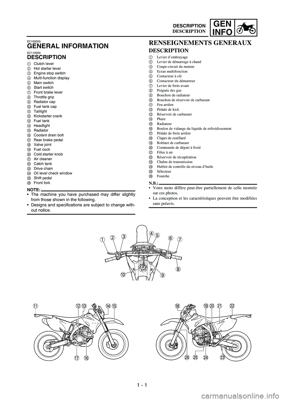
DESCRIPTION
1Clutch lever
2Hot starter lever
3Engine stop switch
4Multi-function display
5Main switch
6Start switch
7Front brake lever
8Throttle grip
9Radiator cap
0Fuel tank cap
ATaillight
BKickstarter crank
CFuel tank
DHeadlight
ERadiator
FCoolant drain bolt
GRear brake pedal
HValve joint
IFuel cock
JCold starter knob
KAir cleaner
LCatch tank
MDrive chain
NOil level check window
OShift pedal
PFront fork
NOTE:The machine you have purchased may differ slightly
from those shown in the following.
Designs and specifications are subject to change with-
out notice.
RENSEIGNEMENTS GENERAUX
DESCRIPTION
1Levier d’embrayage
2Levier de démarrage à chaud
3Coupe-circuit du moteur
4Ecran multifonction
5Contacteur à clé
6Contacteur du démarreur
7Levier de frein avant
8Poignée des gaz
9Bouchon du radiateur
0Bouchon de réservoir de carburant
AFeu arrière
BPédale de kick
CRéservoir de carburant
DPhare
ERadiateur
FBoulon de vidange du liquide de refroidissement
GPédale de frein arrière
HClapet de reniflard
IRobinet de carburant
JCommande de départ à froid
KFiltre à air
LRéservoir de récupération
MChaîne de transmission
NHublot de contrôle du niveau d’huile
OSélecteur
PFourche
N.B.:
Votre moto diffère peut-être partiellement de celle montrée
sur ces photos.
La conception et les caractéristiques peuvent être modifiées
sans préavis.
DESCRIPTION
Page 76 of 912
1 - 51
GEN
INFO
STARTING AND
BREAK-IN
WARNING
Never start or run the engine in a
closed area. The exhaust fumes
are poisonous; they can cause
loss of consciousness and death
in a very short time. Always oper-
ate the machine in a well-venti-
lated area.
CAUTION:
The carburetor on this machine
has a built-in accelerator pump.
Therefore, when starting the
engine, do not operate the throt-
tle or the spark plug will foul.
Unlike a two-stroke engine, this
engine cannot be kick started
when the throttle is open
because the kickstarter may
kick back. Also, if the throttle is
open the air/fuel mixture may be
too lean for the engine to start.
Before starting the machine,
perform the checks in the pre-
operation check list.
AIR FILTER MAINTENANCE
According to “AIR FILTER CLEAN-
ING” section in the CHAPTER 3,
apply the foam-air-filter oil or its
equivalent to the element. (Excess
oil in the element may adversely
affect engine starting.)
STARTING A COLD ENGINE
NOTE:This model is equipped with an igni-
tion circuit cut-off system. The
engine can be started under the fol-
lowing conditions.
When the transmission is in neu-
tral.
When the clutch is disengaged
with the transmission in any posi-
tion. However, it is recommended
to shift into neutral before starting
the engine.
MISE EN MARCHE ET
RODAGE
AVERTISSEMENT
Ne jamais démarrer ou faire tourner
le moteur dans un endroit clos. Les
gaz d’échappement sont nocifs et peu-
vent entraîner très rapidement un éva-
nouissement, voire la mort. Toujours
faire tourner le moteur dans un
endroit bien ventilé.
ATTENTION:
Le carburateur de cette moto est
équipé d’une pompe de reprise inté-
grée. Par conséquent, on ne donnera
pas de gaz en démarrant le moteur
sous peine de noyer la bougie.
A la différence d’un moteur deux
temps, ce moteur ne peut pas être
démarré au kick lorsque le papillon
est ouvert parce que le kick risque
de revenir brutalement. De même, si
le papillon est ouvert, le mélange
air/carburant risque d’être trop
pauvre pour permettre le démar-
rage du moteur.
Avant de mettre le moteur en mar-
che, effectuer les contrôles repris
dans la liste “Contrôles et entretiens
avant utilisation”.
MAINTENANCE DU FILTRE A AIR
Comme indiqué à la section “NET-
TOYAGE DU FILTRE A AIR” du
CHAPITRE 3, appliquer l’huile pour fil-
tre à air mousse ou une huile équivalente
sur la cartouche de filtre. (Un excès
d’huile dans la cartouche peut rendre le
démarrage du moteur plus difficile.)
MISE EN MARCHE A FROID
N.B.:
Ce modèle est équipé d’un coupe-circuit
d’allumage. Il est possible de démarrer le
moteur dans les conditions suivantes.
Lorsque la boîte de vitesses est au
point mort.
En débrayant, dans n’importe quelle
position de la boîte de vitesses. Il est
toutefois recommandé de revenir au
point mort avant de démarrer le
moteur.
STARTING AND BREAK-IN
MISE EN MARCHE ET RODAGE
Page 82 of 912

1 - 57
GEN
INFO
BREAK-IN PROCEDURES
1. Before starting the engine, fill the
fuel tank with the fuel.
2. Perform the pre-operation
checks on the machine.
3. Start and warm up the engine.
Check the idle speed, and check
the operation of the controls and
the engine stop switch. Then,
restart the engine and check its
operation within no more than 5
minutes after it is restarted.
4. Operate the machine in the
lower gears at moderate throttle
openings for five to eight min-
utes.
5. Check how the engine runs
when the machine is ridden with
the throttle 1/4 to 1/2 open (low
to medium speed) for about one
hour.
6. Restart the engine and check
the operation of the machine
throughout its entire operating
range. Restart the machine and
operate it for about 10 to 15
more minutes.
CAUTION:
After the break-in or before each
ride, you must check the entire
machine for loose fittings and fas-
teners as per “TORQUE-CHECK
POINTS”.
Tighten all such fasteners as
required.PROCEDURE DE RODAGE
1. Avant de démarrer le moteur, faire
le plein du réservoir de carburant.
2. Effectuer les contrôles avant utilisa-
tion.
3. Mettre le moteur en marche et le
laisser chauffer. Contrôler le régime
de ralenti et le bon fonctionnement
des commandes et du coupe-circuit
du moteur. Redémarrer ensuite le
moteur et contrôler son fonctionne-
ment dans les 5 minutes maximum
qui suivent son redémarrage.
4. Rouler pendant cinq à huit minutes
sur les rapports inférieurs et à
régime modéré.
5. Contrôler le fonctionnement du
moteur lorsque la moto est utilisée
pendant une heure environ aux régi-
mes bas à moyens (ouverture des
gaz 1/4 à 1/2).
6. Remettre le moteur en marche et
vérifier le fonctionnement de la
moto à toutes les vitesses. Redémar-
rer la moto et rouler pendant 10 à 15
minutes environ.
ATTENTION:
Après le rodage ou avant chaque utili-
sation, il est indispensable de contrôler
le bon serrage des raccords et des fixa-
tions conformément aux instructions
de la section “POINTS DE VERIFI-
CATION DES COUPLES DE SER-
RAGE”.
Resserrer toutes les fixations au
besoin.
STARTING AND BREAK-IN
MISE EN MARCHE ET RODAGE
Page 84 of 912

1 - 59
GEN
INFO
TORQUE-CHECK POINTS
Frame construction Frame to rear frame
Combined seat and fuel tank Fuel tank to frame
Exhaust system Silencer to rear frame
Engine mounting Frame to engine
Engine bracket to engine
Engine bracket to frame
Steering Steering stem to handlebar Steering stem to frame
Steering stem to upper bracket
Upper bracket to handlebar
Suspension Front Steering stem to front fork Front fork to upper bracket
Front fork to lower bracket
Rear For link type Assembly of links
Link to frame
Link to rear shock absorber
Link to swingarm
Rear Installation of rear
shock absorberRear shock absorber to frame
Rear Installation of swingarm Tightening of pivot shaft
Wheel Installation of wheel Front Tightening of wheel axle
Tightening of axle holder
Rear Tightening of wheel axle
Wheel to rear wheel sprocket
Brake Front Brake caliper to front fork
Brake disc to wheel
Tightening of union bolt
Brake master cylinder to handlebar
Tightening of bleed screw
Tightening of brake hose holder
Rear Brake pedal to frame
Brake disc to wheel
Tightening of union bolt
Brake master cylinder to frame
Tightening of bleed screw
Tightening of brake hose holder
Fuel system Fuel tank to fuel cock
Lubrication system Tightening of oil hose clamp
NOTE:Concerning the tightening torque, refer to
“MAINTENANCE SPECIFICATIONS” sec-
tion in the CHAPTER 2.
TORQUE-CHECK POINTS
Page 212 of 912
3 - 1
INSP
ADJ
MAINTENANCE INTERVALS
EC300000
REGULAR INSPECTION AND ADJUSTMENTS
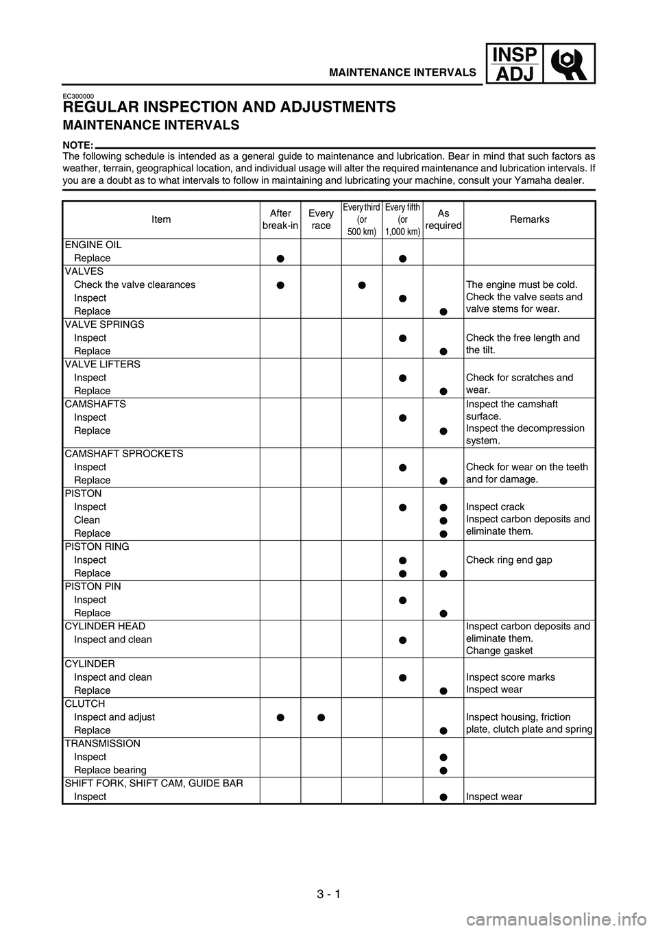
MAINTENANCE INTERVALS
NOTE:The following schedule is intended as a general guide to maintenance and lubrication. Bear in mind that such factors as
weather, terrain, geographical location, and individual usage will alter the required maintenance and lubrication intervals. If
you are a doubt as to what intervals to follow in maintaining and lubricating your machine, consult your Yamaha dealer.
ItemAfter
break-inEvery
race
Every third
(or
500 km)Every fifth
(or
1,000 km)As
requiredRemarks
ENGINE OIL
Replace
VALVES
Check the valve clearances The engine must be cold.
Check the valve seats and
valve stems for wear. Inspect
Replace
VALVE SPRINGS
InspectCheck the free length and
the tilt.
Replace
VALVE LIFTERS
InspectCheck for scratches and
wear.
Replace
CAMSHAFTSInspect the camshaft
surface.
Inspect the decompression
system. Inspect
Replace
CAMSHAFT SPROCKETS
InspectCheck for wear on the teeth
and for damage.
Replace
PISTON
InspectInspect crack
Inspect carbon deposits and
eliminate them. Clean
Replace
PISTON RING
InspectCheck ring end gap
Replace
PISTON PIN
Inspect
Replace
CYLINDER HEADInspect carbon deposits and
eliminate them.
Change gasket Inspect and clean
CYLINDER
Inspect and clean Inspect score marks
Inspect wear
Replace
CLUTCH
Inspect and adjust Inspect housing, friction
plate, clutch plate and spring
Replace
TRANSMISSION
Inspect
Replace bearing
SHIFT FORK, SHIFT CAM, GUIDE BAR
InspectInspect wear
Page 227 of 912
3 - 16
INSP
ADJ
PRE-OPERATION INSPECTION AND MAINTENANCE
EC320000
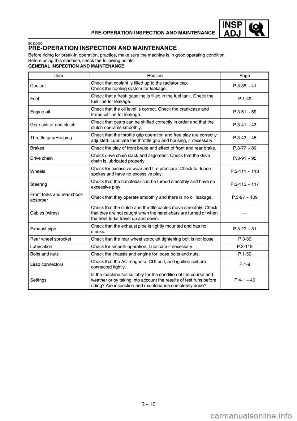
PRE-OPERATION INSPECTION AND MAINTENANCE
Before riding for break-in operation, practice, make sure the machine is in good operating condition.
Before using this machine, check the following points.
GENERAL INSPECTION AND MAINTENANCE
Item Routine Page
CoolantCheck that coolant is filled up to the radiator cap.
Check the cooling system for leakage.P.3-35 ~ 41
FuelCheck that a fresh gasoline is filled in the fuel tank. Check the
fuel line for leakage.P.1-49
Engine oilCheck that the oil level is correct. Check the crankcase and
frame oil line for leakage.P.3-51 ~ 59
Gear shifter and clutchCheck that gears can be shifted correctly in order and that the
clutch operates smoothly.P.3-41 ~ 43
Throttle grip/HousingCheck that the throttle grip operation and free play are correctly
adjusted. Lubricate the throttle grip and housing, if necessary.P.3-43 ~ 45
Brakes Check the play of front brake and effect of front and rear brake. P.3-77 ~ 89
Drive chainCheck drive chain slack and alignment. Check that the drive
chain is lubricated properly.P.3-91 ~ 95
WheelsCheck for excessive wear and tire pressure. Check for loose
spokes and have no excessive play.P.3-111 ~ 113
SteeringCheck that the handlebar can be turned smoothly and have no
excessive play.P.3-113 ~ 117
Front forks and rear shock
absorberCheck that they operate smoothly and there is no oil leakage. P.3-97 ~ 109
Cables (wires)Check that the clutch and throttle cables move smoothly. Check
that they are not caught when the handlebars are turned or when
the front forks travel up and down.—
Exhaust pipeCheck that the exhaust pipe is tightly mounted and has no
cracks.P.3-27 ~ 31
Rear wheel sprocket Check that the rear wheel sprocket tightening bolt is not loose. P.3-89
Lubrication Check for smooth operation. Lubricate if necessary. P.3-119
Bolts and nuts Check the chassis and engine for loose bolts and nuts. P.1-59
Lead connectorsCheck that the AC magneto, CDI unit, and ignition coil are
connected tightly.P.1-9
SettingsIs the machine set suitably for the condition of the course and
weather or by taking into account the results of test runs before
riding? Are inspection and maintenance completely done?P.4-1 ~ 40
Page 244 of 912
3 - 33
INSP
ADJ
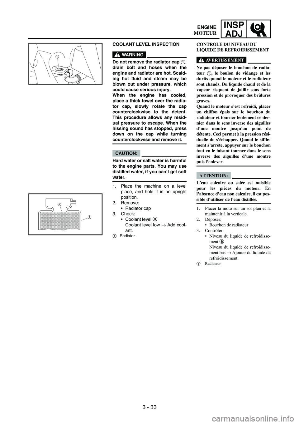
COOLANT LEVEL INSPECTION
WARNING
Do not remove the radiator cap 1,
drain bolt and hoses when the
engine and radiator are hot. Scald-
ing hot fluid and steam may be
blown out under pressure, which
could cause serious injury.
When the engine has cooled,
place a thick towel over the radia-
tor cap, slowly rotate the cap
counterclockwise to the detent.
This procedure allows any resid-
ual pressure to escape. When the
hissing sound has stopped, press
down on the cap while turning
counterclockwise and remove it.
CAUTION:
Hard water or salt water is harmful
to the engine parts. You may use
distilled water, if you can’t get soft
water.
1. Place the machine on a level
place, and hold it in an upright
position.
2. Remove:
Radiator cap
3. Check:
Coolant level
a
Coolant level low
→ Add cool-
ant.
1Radiator
CONTROLE DU NIVEAU DU
LIQUIDE DE REFROIDISSEMENT
AVERTISSEMENT
Ne pas déposer le bouchon de radia-
teur 1, le boulon de vidange et les
durits quand le moteur et le radiateur
sont chauds. Du liquide chaud et de la
vapeur risquent de jaillir sous forte
pression et de provoquer des brûlures
graves.
Quand le moteur s’est refroidi, placer
un chiffon épais sur le bouchon du
radiateur et tourner lentement ce der-
nier dans le sens inverse des aiguilles
d’une montre jusqu’au point de
détente. Ceci permet à la pression rési-
duelle de s’échapper. Quand le siffle-
ment s’arrête, appuyer sur le bouchon
tout en le faisant tourner dans le sens
inverse des aiguilles d’une montre
puis l’enlever.
ATTENTION:
L’eau calcaire ou salée est nuisible
pour les pièces du moteur. En
l’absence d’eau non calcaire, il est pos-
sible d’utiliser de l’eau distillée.
1. Placer la moto sur un sol plan et la
maintenir à la verticale.
2. Déposer:
Bouchon de radiateur
3. Contrôler:
Niveau du liquide de refroidisse-
ment a
Niveau du liquide de refroidisse-
ment bas → Ajouter du liquide de
refroidissement.
1
Radiateur
ENGINE
MOTEUR
Page 248 of 912
3 - 37
INSP
ADJ
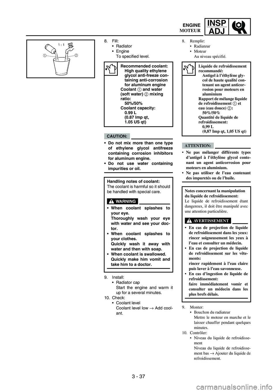
8. Fill:
Radiator
Engine
To specified level.
CAUTION:
Do not mix more than one type
of ethylene glycol antifreeze
containing corrosion inhibitors
for aluminum engine.
Do not use water containing
impurities or oil.
9. Install:
Radiator cap
Start the engine and warm it
up for a several minutes.
10. Check:
Coolant level
Coolant level low
→ Add cool-
ant.
Recommended coolant:
High quality ethylene
glycol anti-freeze con-
taining anti-corrosion
for aluminum engine
Coolant 1 and water
(soft water) 2 mixing
ratio:
50%/50%
Coolant capacity:
0.99 L
(0.87 Imp qt,
1.05 US qt)
Handling notes of coolant:
The coolant is harmful so it should
be handled with special care.
WARNING
When coolant splashes to
your eye.
Thoroughly wash your eye
with water and see your doc-
tor.
When coolant splashes to
your clothes.
Quickly wash it away with
water and then with soap.
When coolant is swallowed.
Quickly make him vomit and
take him to a doctor.
8. Remplir:
Radiateur
Moteur
Au niveau spécifié.
ATTENTION:
Ne pas mélanger différents types
d’antigel à l’éthylène glycol conte-
nant un agent anticorrosion pour
moteurs en aluminium.
Ne pas utiliser de l’eau contenant
des impuretés ou de l’huile.
9. Monter:
Bouchon du radiateur
Mettre le moteur en marche et le
laisser chauffer pendant quelques
minutes.
10. Contrôler:
Niveau du liquide de refroidisse-
ment
Niveau du liquide de refroidisse-
ment bas → Ajouter du liquide de
refroidissement.
Liquide de refroidissement
recommandé:
Antigel à l’éthylène gly-
col de haute qualité con-
tenant un agent anticor-
rosion pour moteurs en
aluminium
Rapport de mélange liquide
de refroidissement 1 et
eau (eau douce) 2:
50%/50%
Quantité de liquide de
refroidissement:
0,99 L
(0,87 Imp qt, 1,05 US qt)
Notes concernant la manipulation
du liquide de refroidissement:
Le liquide de refroidissement étant
dangereux, il doit être manipulé avec
une attention particulière.
AVERTISSEMENT
En cas de projection de liquide
de refroidissement dans les yeux:
rincer soigneusement les yeux à
l’eau et consulter un médecin.
En cas de projection de liquide
de refroidissement sur les vête-
ments:
rincer rapidement à l’eau claire
puis laver à l’eau savonneuse.
En cas d’ingestion de liquide de
refroidissement:
faire immédiatement vomir et
consulter un médecin dans les
plus brefs délais.
ENGINE
MOTEUR