YAMAHA WR 250F 2008 Service Manual
Manufacturer: YAMAHA, Model Year: 2008, Model line: WR 250F, Model: YAMAHA WR 250F 2008Pages: 224, PDF Size: 13.66 MB
Page 41 of 224
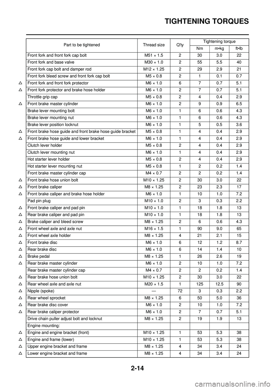
2-14
TIGHTENING TORQUES
Front fork and front fork cap boltM51 × 1.5 2 30 3.0 22
Front fork and base valve M30 × 1.0 2 55 5.5 40
Front fork cap bolt and damper rod M12 × 1.25 2 29 2.9 21
Front fork bleed screw and front fork cap bolt M5 × 0.8 2 1 0.1 0.7
△ Front fork and front fork protector M6 × 1.0 6 7 0.7 5.1
△ Front fork protector and brake hose holder M6 × 1.0 2 7 0.7 5.1
Throttle grip cap M5 × 0.8 2 4 0.4 2.9
△ Front brake master cylinder M6 × 1.0 2 9 0.9 6.5
Brake lever mounting bolt M6 × 1.0 1 6 0.6 4.3
Brake lever mounting nut M6 × 1.0 1 6 0.6 4.3
Brake lever position locknut M6 × 1.0 1 5 0.5 3.6
△ Front brake hose guide and front brake hose guide bracket M5 × 0.8 1 4 0.4 2.9
△ Front brake hose guide and lower bracket M6 × 1.0 1 4 0.4 2.9
Clutch lever holder M5 × 0.8 2 4 0.4 2.9
Clutch lever mounting nut M6 × 1.0 1 4 0.4 2.9
Hot starter lever holder M5 × 0.8 2 4 0.4 2.9
Hot starter lever mounting nut M5 × 0.8 1 2 0.2 1.4
Front brake master cylinder cap M4 × 0.7 2 2 0.2 1.4
△ Front brake hose union bolt M10 × 1.25 2 30 3.0 22
△ Front brake caliper M8 × 1.25 2 23 2.3 17
△ Front brake caliper and brake hose holder M6 × 1.0 1 10 1.0 7.2
Pad pin plug M10 × 1.0 2 3 0.3 2.2
△ Front brake caliper and pad pin M10 × 1.0 1 18 1.8 13
△ Rear brake caliper and pad pin M10 × 1.0 1 18 1.8 13
△ Brake caliper and bleed screw M8 × 1.25 2 6 0.6 4.3
△ Front wheel axle and axle nut M16 × 1.5 1 90 9.0 65
△ Front wheel axle holder M8 × 1.25 4 21 2.1 15
△ Front brake disc M6 × 1.0 6 12 1.2 8.7
△ Rear brake disc M6 × 1.0 6 14 1.4 10
△ Brake pedal M8 × 1.25 1 26 2.6 19
△ Rear brake master cylinder M6 × 1.0 2 10 1.0 7.2
Rear brake master cylinder cap M4 × 0.7 2 2 0.2 1.4
△ Rear brake hose union bolt M10 × 1.25 2 30 3.0 22
△ Rear wheel axle and axle nut M20 × 1.5 1 125 12.5 90
△ Nipple (spoke) —72 3 0.3 2.2
△ Rear wheel sprocket M8 × 1.25 6 50 5.0 36
△ Rear brake disc cover M6 × 1.0 2 10 1.0 7.2
△ Rear brake caliper protector M6 × 1.0 2 7 0.7 5.1
Drive chain puller adjust bolt and locknut M8 × 1.25 2 19 1.9 13
Engine mounting:
△ Engine and engine bracket (front) M10 × 1.25 1 53 5.3 38
△ Engine and frame (lower) M10 × 1.25 1 53 5.3 38
△ Upper engine bracket and frame M8 × 1.25 4 34 3.4 24
△ Lower engine bracket and frame M8 × 1.25 4 34 3.4 24
Part to be tightened
Thread size Q'tyTightening torque
Nm m•kg ft•lb
Page 42 of 224

2-15
TIGHTENING TORQUES
△Engine and engine bracket (upper) M10 × 1.25 1 55 5.5 40
△ Engine guard M6 × 1.0 3 7 0.7 5.1
Regulator M6 × 1.0 2 7 0.7 5.1
△ Pivot shaft and nut M16 × 1.5 1 85 8.5 61
△ Relay arm and swingarm M14 × 1.5 1 70 7.0 50
△ Relay arm and connecting rod M14 × 1.5 1 80 8.0 58
△ Connecting rod and frame M14 × 1.5 1 80 8.0 58
△ Rear shock absorber and frame M10 × 1.25 1 56 5.6 40
△ Rear shock absorber and relay arm M10 × 1.25 1 53 5.3 38
△ Rear frame (upper) M8 × 1.25 1 38 3.8 27
△ Rear frame (lower) M8 × 1.25 2 32 3.2 23
△ Swingarm and brake hose holder M5 × 0.8 4 2 0.2 1.4
Swingarm and patch M4 × 0.7 4 2 0.2 1.4
Upper drive chain tensioner M8 × 1.25 1 16 1.6 11
Lower drive chain tensioner M8 × 1.25 1 16 1.6 11
Drive chain support M6 × 1.0 3 7 0.7 5.1
Seal guard and swingarm M5 × 0.8 4 6 0.6 4.3
△ Fuel tank M6 × 1.0 2 9 0.9 6.5
△ Fuel cock M6 × 1.0 2 4 0.4 2.9
Seat set bracket and fuel tank M6 × 1.0 1 7 0.7 5.1
Fuel tank bracket and fuel tank M6 × 1.0 4 7 0.7 5.1
△ Air scoop and fuel tank M6 × 1.0 6 7 0.7 5.1
△ Air scoop and radiator guard (lower) M6 × 1.0 2 6 0.6 4.3
△ Front fender M6 × 1.0 4 7 0.7 5.1
△ Rear fender (front) M6 × 1.0 2 7 0.7 5.1
△ Rear fender (rear) M6 × 1.0 2 11 1.1 8.0
△ Side cover M6 × 1.0 2 7 0.7 5.1
△ Seat M8 × 1.25 2 23 2.3 17
Multi-function display bracket and upper bracket M6 × 1.0 2 7 0.7 5.1
Multi-function display M5 × 0.8 2 4 0.4 2.9
Plate 1 and front fork protector M5 × 0.8 2 4 0.4 2.9
Plate 2 and front fork protector —2 0.5 0.05 0.36
Speed sensor lead holder and lower bracket M6 × 1.0 1 13 1.3 9.4
Speed sensor lead holder and clamp M6 × 1.0 1 7 0.7 5.1
Headlight body and headlight unit —2 1 0.1 0.7
△ Headlight M6 × 1.0 2 7 0.7 5.1
Taillight —3 1 0.1 0.7
Taillight lead clamp and rear fender —3 0.5 0.05 0.36
△ Catch tank (upper) M6 × 1.0 1 16 1.6 11
△ Catch tank (lower) M6 × 1.0 1 7 0.7 5.1
Footrest bracket and frame M10 × 1.25 4 55 5.5 40
Sidestand M10 × 1.25 1 25 2.5 18
Part to be tightened
Thread size Q'tyTightening torque
Nm m•kg ft•lb
Page 43 of 224

2-16
TIGHTENING TORQUES
1. First, tighten the steering ring nut approximately 38 Nm (3.8 m•kg, 27 ft•lb) by using the steering nut wrench, then loosen
the steering ring nut one turn.
2. Retighten the steering ring nut 7 Nm (0.7 m•kg, 5.1 ft•lb).
ELECTRICAL
Tighten the rotor nut to 65 Nm (6.5 m•kg, 47 ft•lb), loosen and retighten the rotor nut to 65 Nm (6.5 m •kg, 47 ft•lb).
Part to be tightened Thread size Q'tyTightening torque
Nm m•kg ft•lb
Stator M5 × 0.8 2 7 0.7 5.1
Holder (AC magneto lead) M5× 0.8 2 7 0.7 5.1
Rotor M12 × 1.25 1Refer to NOTE.
Neutral switch M5 × 0.8 2 4 0.4 2.9
Starter motor M6 × 1.0 2 10 1.0 7.2
Starter relay terminal M6 × 1.0 2 4 0.4 2.9
Negative lead and cylinder head M6 × 1.0 1 10 1.0 7.2
Pickup coil M6 × 1.0 2 10 1.0 7.2
Page 44 of 224
2-17
TIGHTENING TORQUES
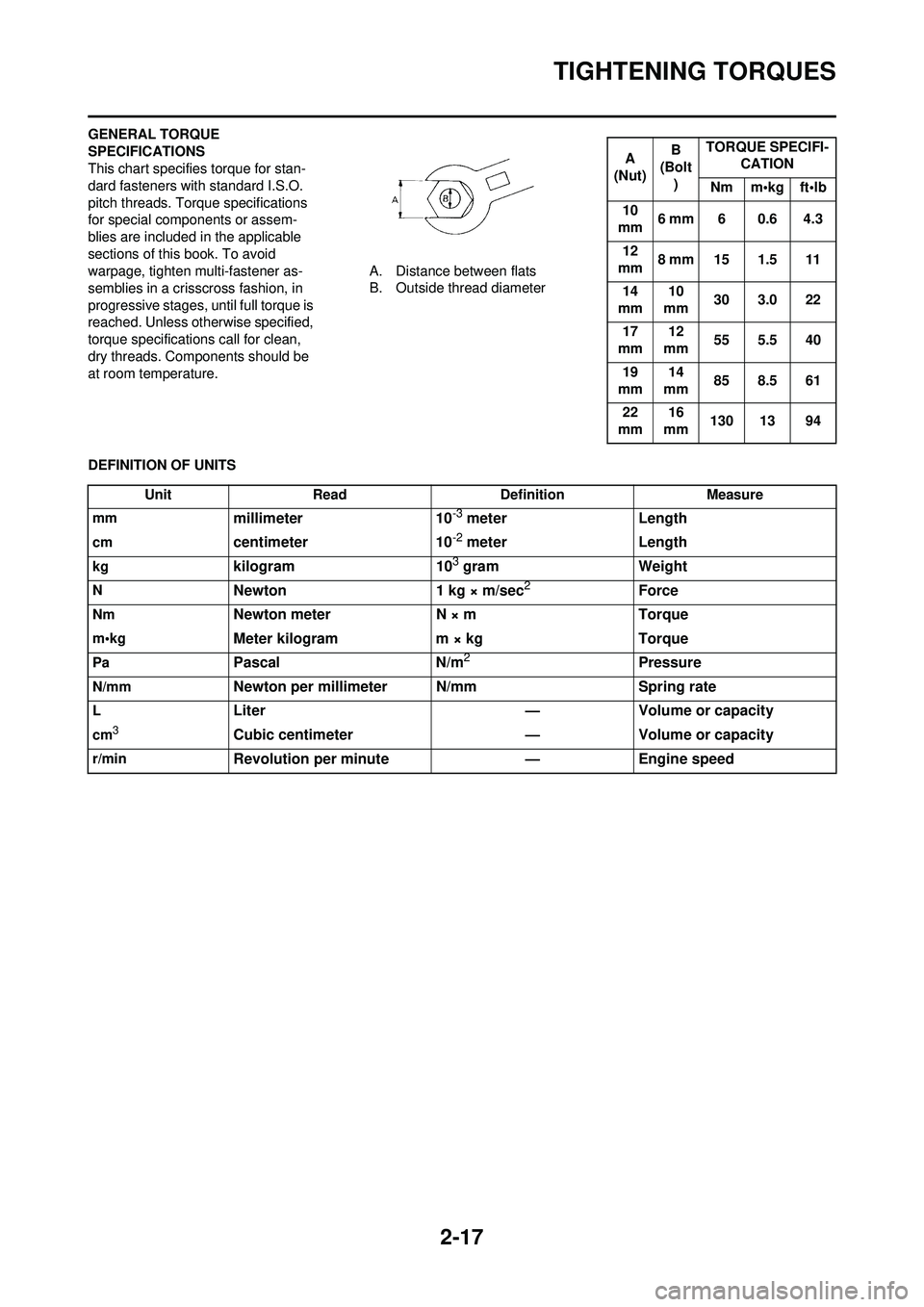
GENERAL TORQUE
SPECIFICATIONS
This chart specifies torque for stan-
dard fasteners with standard I.S.O.
pitch threads. Torque specifications
for special components or assem-
blies are included in the applicable
sections of this book. To avoid
warpage, tighten multi-fastener as-
semblies in a crisscross fashion, in
progressive stages, until full torque is
reached. Unless otherwise specified,
torque specifications call for clean,
dry threads. Components should be
at room temperature. A. Distance between flats
B. Outside thread diameter
DEFINITION OF UNITS
A
(Nut) B
(Bolt
) TORQUE SPECIFI-
CATION
Nm m•kg ft•lb
10
mm 6 mm 6 0.6 4.3
12
mm 8 mm 15 1.5 11
14
mm 10
mm 30 3.0 22
17
mm 12
mm 55 5.5 40
19
mm 14
mm 85 8.5 61
22
mm 16
mm 130 13 94
Unit
Read Definition Measure
mm
millimeter 10-3 meterLength
cmcentimeter 10-2 meterLength
kgkilogram 103 gramWeight
NNewton 1 kg × m/sec2Force
NmNewton meter N × mTorque
m•kgMeter kilogram m × kg Torque
PaPascalN/m2Pressure
N/mmNewton per millimeter N/mm Spring rate
LLiter—Volume or capacity
cm3Cubic centimeter —Volume or capacity
r/minRevolution per minute —Engine speed
Page 45 of 224

2-18
LUBRICATION DIAGRAMS
LUBRICATION DIAGRAMS
1. Oil filter element
2. Oil pump
3. Drive axle
4. Main axle
5. Intake camshaft
6. Exhaust camshaft
7. Oil tank
8. Oil delivery pipe
A. To oil tank
Page 46 of 224
2-19
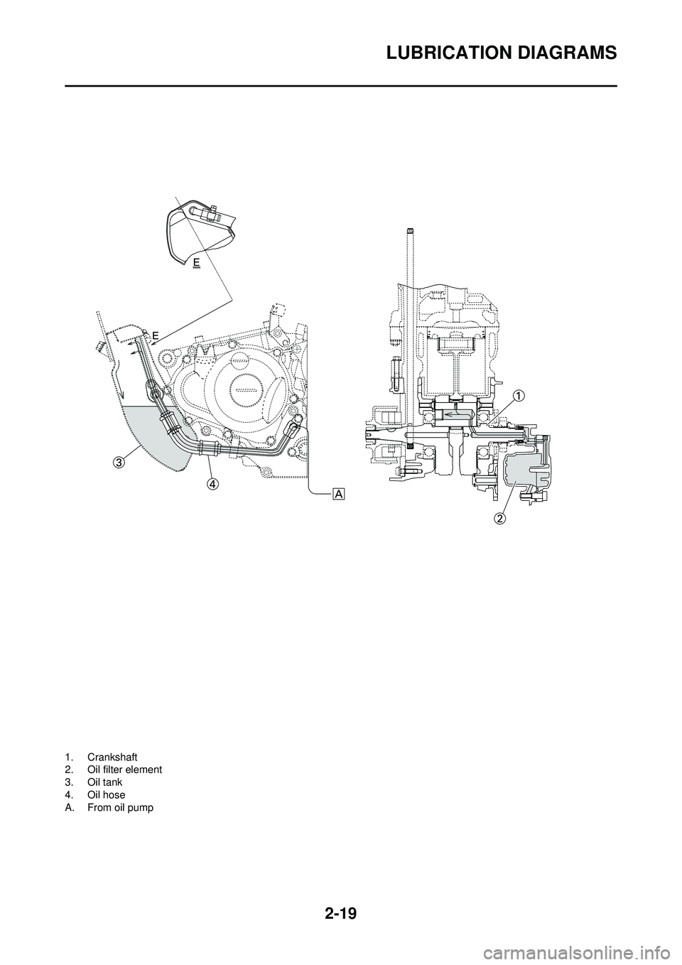
LUBRICATION DIAGRAMS
1. Crankshaft
2. Oil filter element
3. Oil tank
4. Oil hose
A. From oil pump
Page 47 of 224
2-20
LUBRICATION DIAGRAMS
Page 48 of 224

2-21
CABLE ROUTING DIAGRAM
CABLE ROUTING DIAGRAM
1. Fuel tank breather hose
2. Clamp
3. Diode
4. Hot starter cable
5. Wire harness
6. Hump (frame)
7. Cylinder head breather hose
8. Throttle position sensor lead
9. Neutral switch lead10. Oil hose
11. Clutch cable
12. Starter motor lead
13. Cable guide
14. Negative battery lead
15. AC magneto lead
16. Brake hose
17. Rectifier/regulator lead
18. Carburetor breather hose 19. Carburetor overflow hose
20. Catch tank breather hose
Page 49 of 224

2-22
CABLE ROUTING DIAGRAM
A. Insert the end of the fuel tank breather hose into the hole in
the steering stem.
B. Fasten the throttle cable, hot
starter cable and rectifier/regula-
tor lead onto the frame. Locate
the clamp end facing the lower
side of the hot starter cable and
cut off the tie end.
C. Fasten the diode (at the mark-
ing), throttle cable and hot start-
er cable onto the frame. Locate
the clamp end facing toward the
lower right of the frame and with
the tie end facing downward.
D. Fasten the wire harness, throttle
position sensor lead, starter mo-
tor lead and negative battery
lead onto the frame. Pass the
clamp through the hole in the
stay (air cut-off valve). Locate
the clamp end facing toward the
lower side of the frame and cut
off the tie end.
E. Fasten the throttle position sen-
sor lead onto the frame. Locate
the clamp end facing toward the
lower side of the frame and cut
off the tie end.
F. Pass the carburetor breather hoses, carburetor overflow hose
and catch tank breather hose
between the connecting rod and
cross tube (frame).
G. Fasten the neutral switch lead and oil hose together with the
plastic locking ties and cut off
the tie ends.
H. Fasten the neutral switch lead
and AC magneto lead onto the
frame. Locate the clamp end
facing toward the outside of the
frame and tie end facing toward
the rear of the frame.
I. Pass the clutch cable through
the cable guide.
J. Fasten the starter motor lead, AC magneto lead and neutral
switch lead onto the frame. Lo-
cate the clamp end facing to-
ward the rear of the frame and
cut off the tie end.
K. Fasten the clutch cable, starter motor lead, negative battery
lead, AC magneto lead and neu-
tral switch lead onto the frame.
Locate the clamp end facing to-
ward the rear of the frame and
cut off the tie end.
L. Pass the neutral switch lead and
AC magneto lead on the inside
of the wire harness. M. Fasten the clutch cable, AC
magneto lead and neutral switch
lead onto the frame. Locate the
clamp end near the clutch cable
and cut off the tie end.
N. Pass the clutch cable and wire harness through the cable
guide.
O. Locate the couplers in the frame recess.
P. Pass the carburetor breather hoses, carburetor overflow hose
and catch tank breather hose so
that the hoses do not contact the
rear shock absorber.
Q. Secure the coupler by pushing it
into the hole in the headlight
unit.
Page 50 of 224
2-23
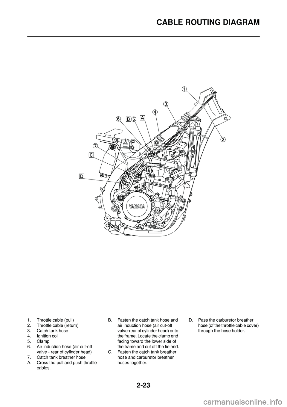
CABLE ROUTING DIAGRAM
1. Throttle cable (pull)
2. Throttle cable (return)
3. Catch tank hose
4. Ignition coil
5. Clamp
6. Air induction hose (air cut-off valve - rear of cylinder head)
7. Catch tank breather hose
A. Cross the pull and push throttle cables. B. Fasten the catch tank hose and
air induction hose (air cut-off
valve-rear of cylinder head) onto
the frame. Locat e the clamp end
facing toward the lower side of
the frame and cut off the tie end.
C. Fasten the catch tank breather hose and carburetor breather
hoses together. D. Pass the carburetor breather
hose (of the throttle cable cover)
through the hose holder.