fuel pump YAMAHA WR 250F 2009 Owners Manual
[x] Cancel search | Manufacturer: YAMAHA, Model Year: 2009, Model line: WR 250F, Model: YAMAHA WR 250F 2009Pages: 224, PDF Size: 13.93 MB
Page 10 of 224
1-2
MACHINE IDENTIFICATION
MACHINE IDENTIFICATION
There are two significant reasons for
knowing the serial number of your
machine:
1. When ordering parts, you can give the number to your Yamaha
dealer for positive identification of
the model you own.
2. If your machine is stolen, the au-
thorities will need the number to
search for and identify your ma-
chine.
VEHICLE IDENTIFICATION
NUMBER
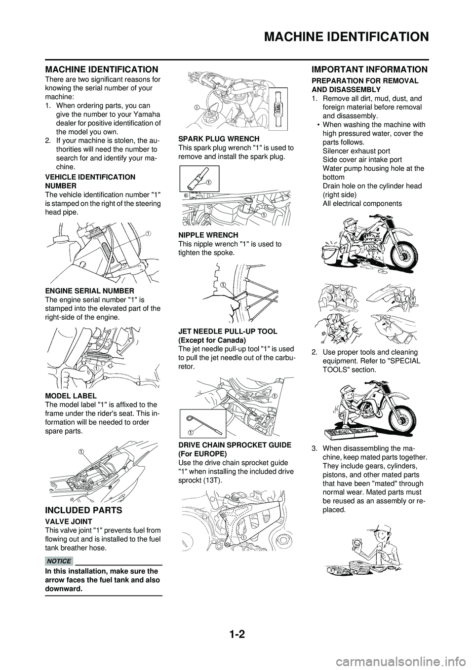
The vehicle identification number "1"
is stamped on the right of the steering
head pipe.
ENGINE SERIAL NUMBER
The engine serial number "1" is
stamped into the elevated part of the
right-side of the engine.
MODEL LABEL
The model label "1" is affixed to the
frame under the rider's seat. This in-
formation will be needed to order
spare parts.
INCLUDED PARTS
VALVE JOINT
This valve joint "1" prevents fuel from
flowing out and is installed to the fuel
tank breather hose.
In this installation, make sure the
arrow faces the fuel tank and also
downward.
SPARK PLUG WRENCH
This spark plug wrench "1" is used to
remove and install the spark plug.
NIPPLE WRENCH
This nipple wrench "1" is used to
tighten the spoke.
JET NEEDLE PULL-UP TOOL
(Except for Canada)
The jet needle pull-up tool "1" is used
to pull the jet needle out of the carbu-
retor.
DRIVE CHAIN SPROCKET GUIDE
(For EUROPE)
Use the drive chain sprocket guide
"1" when installing the included drive
sprockt (13T).
IMPORTANT INFORMATION
PREPARATION FOR REMOVAL
AND DISASSEMBLY
1. Remove all dirt, mud, dust, and foreign material before removal
and disassembly.
• When washing the machine with high pressured water, cover the
parts follows.
Silencer exhaust port
Side cover air intake port
Water pump housing hole at the
bottom
Drain hole on the cylinder head
(right side)
All electrical components
2. Use proper tools and cleaning equipment. Refer to "SPECIAL
TOOLS" section.
3. When disassembling the ma- chine, keep mated parts together.
They include gears, cylinders,
pistons, and other mated parts
that have been "mated" through
normal wear. Mated parts must
be reused as an assembly or re-
placed.
Page 22 of 224
1-14
STARTING AND BREAK-IN
STARTING AND BREAK-IN
FUEL
Always use the recommended fuel as
stated below. Also, be sure to use
new gasoline.
Use only unleaded gasoline. The
use of leaded gasoline will cause
severe damage to the engine inter-
nal parts such as valves, piston
rings, and exhaust system, etc.
If knocking or pinging occurs, use a
different brand of gasoline or higher
octane grade.
• For refueling, be sure to stop the engine and use enough care not
to spill any fuel. Also be sure to
avoid refueling close to a fire.
• Refuel after the engine, exhaust
pipe, etc. have cooled off.
Gasohol (For Canada)
There are two types of gasohol: gas-
ohol containing ethanol and that con-
taining methanol. Gasohol containing
ethanol can be used if the ethanol
content does not exceed 10%. Gaso-
hol containing methanol is not recom-
mended by Yamaha because it can
cause damage to the fuel system or
vehicle performance problems.
HANDLING NOTE
Never start or run the engine in a
closed area. The exhaust fumes
are poisonous; they can cause
loss of consciousness and death
in a very short time. Always oper-
ate the machine in a well-ventilated
area.
• The carburetor on this machine has a built-in accelerator pump.
Therefore, when starting the en-
gine, do not operate the throttle
or the spark plug will foul.
• Unlike a two-stroke engine, this engine cannot be kick started
when the throttle is open be-
cause the kickstarter may kick
back. Also, if the throttle is open
the air/fuel mixture may be too
lean for the engine to start.
• Before starting the machine, per- form the checks in the pre-opera-
tion check list.
AIR FILTER MAINTENANCE
According to "CLEANING THE AIR
FILTER ELEMENT" section in the
CHAPTER 3, apply the foam-air-filter
oil or its equivalent to the element.
(Excess oil in the element may ad-
versely affect engine starting.)
STARTING A COLD ENGINE
This model is equipped with an igni-
tion circuit cut-off system. The engine
can be started under the following
conditions.
• When the transmission is in neutral.
• When the clutch is disengaged with
the transmission in any position.
However, it is recommended to shift
into neutral before starting the en-
gine.
1. Inspect the coolant level.
2. Turn the fuel cock to "ON".
3. Push on the main switch to "ON".
4. Shift the transmission into neutral.
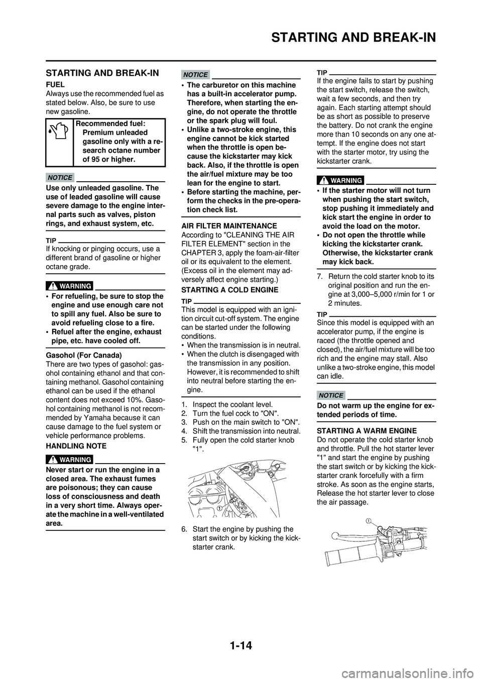
5. Fully open the cold starter knob "1".
6. Start the engine by pushing the start switch or by kicking the kick-
starter crank.
If the engine fails to start by pushing
the start switch, release the switch,
wait a few seconds, and then try
again. Each starting attempt should
be as short as possible to preserve
the battery. Do not crank the engine
more than 10 seconds on any one at-
tempt. If the engine does not start
with the starter motor, try using the
kickstarter crank.
• If the starter motor will not turn
when pushing the start switch,
stop pushing it immediately and
kick start the engine in order to
avoid the load on the motor.
• Do not open the throttle while
kicking the kickstarter crank.
Otherwise, the kickstarter crank
may kick back.
7. Return the cold starter knob to its original position and run the en-
gine at 3,000–5,000 r/min for 1 or
2 minutes.
Since this model is equipped with an
accelerator pump, if the engine is
raced (the throttle opened and
closed), the air/fuel mixture will be too
rich and the engine may stall. Also
unlike a two-stroke engine, this model
can idle.
Do not warm up the engine for ex-
tended periods of time.
STARTING A WARM ENGINE
Do not operate the cold starter knob
and throttle. Pull the hot starter lever
"1" and start the engine by pushing
the start switch or by kicking the kick-
starter crank forcefully with a firm
stroke. As soon as the engine starts,
Release the hot starter lever to close
the air passage.
Recommended fuel:
Premium unleaded
gasoline only with a re-
search octane number
of 95 or higher.
Page 69 of 224
3-16
ENGINE
CHECKING THE OIL PRESSURE
1. Check:•Oil pressure
Checking steps:
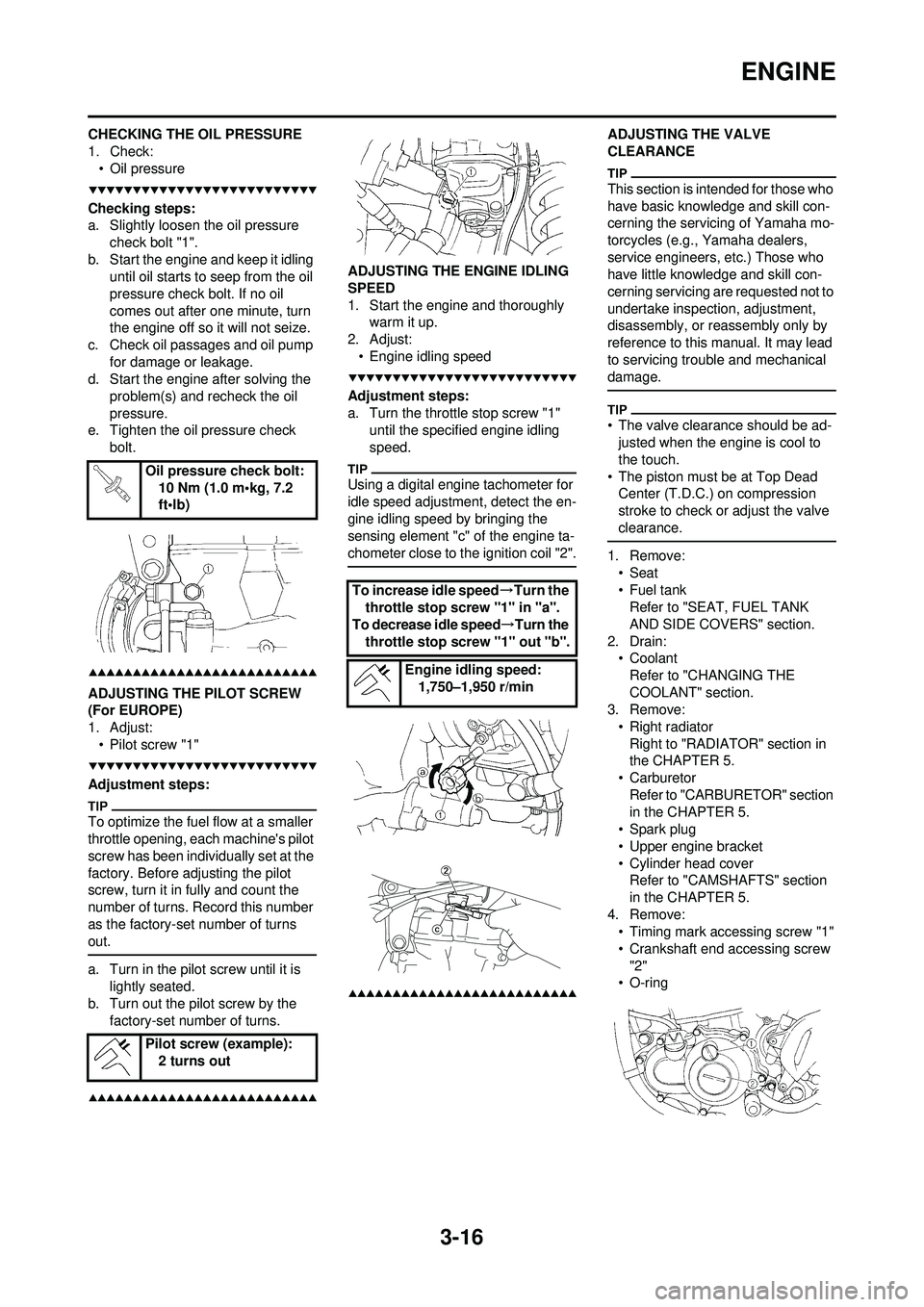
a. Slightly loosen the oil pressure check bolt "1".
b. Start the engine and keep it idling until oil starts to seep from the oil
pressure check bolt. If no oil
comes out after one minute, turn
the engine off so it will not seize.
c. Check oil passages and oil pump for damage or leakage.
d. Start the engine after solving the
problem(s) and recheck the oil
pressure.
e. Tighten the oil pressure check
bolt.
ADJUSTING THE PILOT SCREW
(For EUROPE)
1. Adjust:• Pilot screw "1"
Adjustment steps:
To optimize the fuel flow at a smaller
throttle opening, each machine's pilot
screw has been individually set at the
factory. Before adjusting the pilot
screw, turn it in fully and count the
number of turns. Record this number
as the factory-set number of turns
out.
a. Turn in the pilot screw until it is lightly seated.
b. Turn out the pilot screw by the
factory-set number of turns.
ADJUSTING THE ENGINE IDLING
SPEED
1. Start the engine and thoroughly warm it up.
2. Adjust: • Engine idling speed
Adjustment steps:
a. Turn the throttle stop screw "1" until the specified engine idling
speed.
Using a digital engine tachometer for
idle speed adjustment, detect the en-
gine idling speed by bringing the
sensing element "c" of the engine ta-
chometer close to the ignition coil "2".
ADJUSTING THE VALVE
CLEARANCE
This section is intended for those who
have basic knowledge and skill con-
cerning the servicing of Yamaha mo-
torcycles (e.g., Yamaha dealers,
service engineers, etc.) Those who
have little knowledge and skill con-
cerning servicing are requested not to
undertake inspection, adjustment,
disassembly, or reassembly only by
reference to this manual. It may lead
to servicing trouble and mechanical
damage.
• The valve clearance should be ad-justed when the engine is cool to
the touch.
• The piston must be at Top Dead Center (T.D.C.) on compression
stroke to check or adjust the valve
clearance.
1. Remove:
•Seat
• Fuel tankRefer to "SEAT, FUEL TANK
AND SIDE COVERS" section.
2. Drain: • Coolant
Refer to "CHANGING THE
COOLANT" section.
3. Remove:
• Right radiatorRight to "RADIATOR" section in
the CHAPTER 5.
•Carburetor Refer to "CARBURETOR" section
in the CHAPTER 5.
• Spark plug
• Upper engine bracket
• Cylinder head cover Refer to "CAMSHAFTS" section
in the CHAPTER 5.
4. Remove: • Timing mark accessing screw "1"
• Crankshaft end accessing screw
"2"
• O-ring
Oil pressure check bolt:
10 Nm (1.0 m•kg, 7.2
ft•lb)
Pilot screw (example): 2 turns out
To increase idle speed →Turn the
throttle stop screw "1" in "a".
To decrease idle speed→Turn the
throttle stop screw "1" out "b".
Engine idling speed:1,750–1,950 r/min
Page 88 of 224
4-1
ENGINE (Except for Canada)
TUNING
ENGINE (Except for Canada)
CARBURETOR SETTING
• The air/fuel mixture will vary de-pending on atmospheric conditions.
Therefore, it is necessary to take
into consideration the air pressure,
ambient temperature, humidity,
etc., when adjusting the carburetor.
• Perform a test run to check for prop- er engine performance (e.g., throt-
tle response) and spark plug(-s)
discoloration or fouling. Use these
readings to determine the best pos-
sible carburetor setting.
It is recommended to keep a record of
all carburetor settings and external
conditions (e.g., atmospheric condi-
tions, track/surface conditions, lap
times) to make future carburetor set-
ting easier.
• The carburetor is a part of the fuel line. Therefore, be sure to in-
stall it in a wellventilated area,
away from flammable objects
and any sources of fire.
• Never look into the carburetor in- take. Flames may shoot out from
the pipe if the engine backfires
while it is being started. Gasoline
may be discharged from the ac-
celerator pump nozzle when the
carburetor has been removed.
• The carburetor is extremely sen-sitive to foreign matter (dirt,
sand, water, etc.). During instal-
lation, do not allow foreign mat-
ter to get into the carburetor.
• Always handle the carburetor and its components carefully.
Even slight scratches, bends or
damage to carburetor parts may
prevent the carburetor from
functioning correctly. Carefully
perform all servicing with the ap-
propriate tools and without ap-
plying excessive force.
• When the engine is stopped or when riding at no load, do not
open and close the throttle un-
necessarily. Otherwise, too
much fuel may be discharged,
starting may become difficult or
the engine may not run well. • After installing the carburetor,
check that the throttle operates
correctly and opens and closes
smoothly.
ATMOSPHERIC CONDITIONS AND
CARBURETOR SETTINGS
The air density (i.e., concentration of
oxygen in the air) determines the rich-
ness or leanness of the air/fuel mix-
ture.
• Higher temperature expands the air with its resultant reduced density.
• Higher humidity reduces the
amount of oxygen in the air by so
much of the water vapor in the
same air.
• Lower atmospheric pressure (at a high altitude) reduces the density of
the air.
EFFECT OF SETTING PARTS IN
RELATION TO THROTTLE VALVE
OPENING
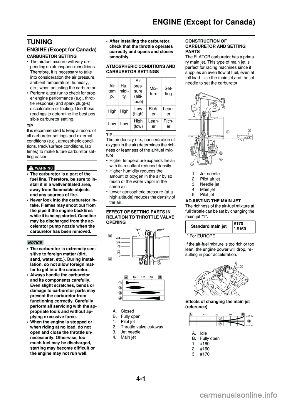
A. Closed
B. Fully open
1. Pilot jet
2. Throttle valve cutaway
3. Jet needle
4. Main jet CONSTRUCTION OF
CARBURETOR AND SETTING
PARTS
The FLATCR carburetor has a prima-
ry main jet. This type of main jet is
perfect for racing machines since it
supplies an even flow of fuel, even at
full load. Use the main jet and the jet
needle to set the carburetor.
1. Jet needle
2. Pilot air jet
3. Needle jet
4. Main jet
5. Pilot jet
ADJUSTING THE MAIN JET
The richness of the air-fuel mixture at
full throttle can be set by changing the
main jet "1".
If the air-fuel mixture is too rich or too
lean, the engine power will drop, re-
sulting in poor acceleration.
Effects of changing the main jet
(reference)
A. Idle
B. Fully open
1. #180
2. #160
3. #170
Air
tem
p. Hu-
midi-
ty Air
pres- sure
(alti-
tude) Mix-
ture Set-
ting
High High Low
(high) Rich-
er Lean-
er
Low Low High
(low) Lean-
er Rich-
er
Standard main jet #170
* #160
* For EUROPE
Page 89 of 224
4-2
ENGINE (Except for Canada)
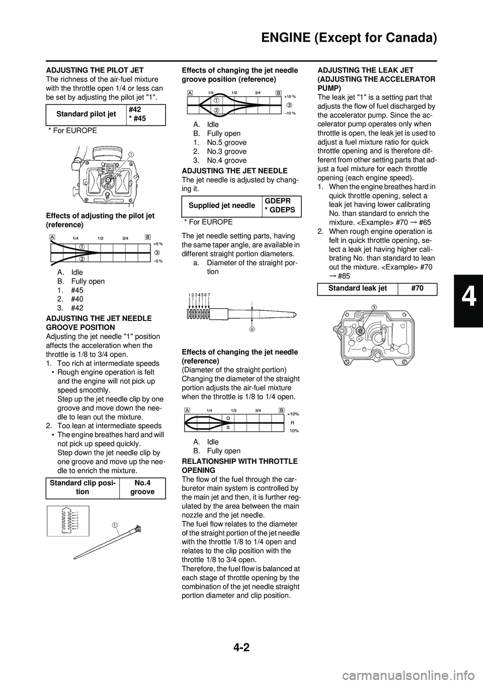
ADJUSTING THE PILOT JET
The richness of the air-fuel mixture
with the throttle open 1/4 or less can
be set by adjusting the pilot jet "1".
Effects of adjusting the pilot jet
(reference)A. Idle
B. Fully open
1. #45
2. #40
3. #42
ADJUSTING THE JET NEEDLE
GROOVE POSITION
Adjusting the jet needle "1" position
affects the acceleration when the
throttle is 1/8 to 3/4 open.
1. Too rich at intermediate speeds • Rough engine operation is felt
and the engine will not pick up
speed smoothly.
Step up the jet needle clip by one
groove and move down the nee-
dle to lean out the mixture.
2. Too lean at intermediate speeds
• The engine breathes hard and will not pick up speed quickly.
Step down the jet needle clip by
one groove and move up the nee-
dle to enrich the mixture. Effects of changing the jet needle
groove position (reference)
A. Idle
B. Fully open
1. No.5 groove
2. No.3 groove
3. No.4 groove
ADJUSTING THE JET NEEDLE
The jet needle is adjusted by chang-
ing it.
The jet needle setting parts, having
the same taper angle, are available in
different straight portion diameters. a. Diameter of the straight por- tion
Effects of changing the jet needle
(reference)
(Diameter of the straight portion)
Changing the diameter of the straight
portion adjusts the air-fuel mixture
when the throttle is 1/8 to 1/4 open. A. Idle
B. Fully open
RELATIONSHIP WITH THROTTLE
OPENING
The flow of the fuel through the car-
buretor main system is controlled by
the main jet and then, it is further reg-
ulated by the area between the main
nozzle and the jet needle.
The fuel flow relates to the diameter
of the straight portion of the jet needle
with the throttle 1/8 to 1/4 open and
relates to the clip position with the
throttle 1/8 to 3/4 open.
Therefore, the fuel flow is balanced at
each stage of throttle opening by the
combination of the jet needle straight
portion diameter and clip position. ADJUSTING THE LEAK JET
(ADJUSTING THE ACCELERATOR
PUMP)
The leak jet "1" is a setting part that
adjusts the flow of fuel discharged by
the accelerator pump. Since the ac-
celerator pump operates only when
throttle is open, the leak jet is used to
adjust a fuel mixture ratio for quick
throttle opening and is therefore dif-
ferent from other setting parts that ad-
just a fuel mixture for each throttle
opening (each engine speed).
1. When the engine breathes hard in
quick throttle opening, select a
leak jet having lower calibrating
No. than standard to enrich the
mixture.
2. When rough engine operation is
felt in quick throttle opening, se-
lect a leak jet having higher cali-
brating No. than standard to lean
out the mixture.
→#85
Standard pilot jet
#42
* #45
* For EUROPE
Standard clip posi- tion No.4
groove
Supplied jet needle GDEPR
* GDEPS
* For EUROPE
Standard leak jet #70
4
Page 91 of 224
4-4
ENGINE (Except for Canada)
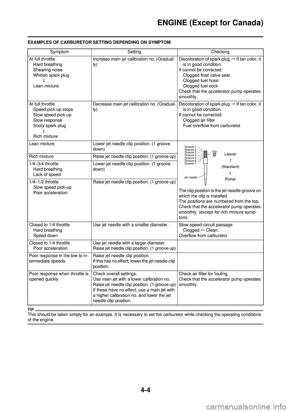
EXAMPLES OF CARBURETOR SETTING DEPENDING ON SYMPTOM
This should be taken simply for an example. It is necessary to set the carburetor while checking the operating conditions
of the engine.
SymptomSetting Checking
At full throttle Hard breathing
Shearing noise
Whitish spark plug ↓
Lean mixture Increase main jet calibration no. (Gradual-
ly)
Discoloration of spark plug
→If tan color, it
is in good condition.
If cannot be corrected: Clogged float valve seat
Clogged fuel hose
Clogged fuel cock
Check that the accelerator pump operates
smoothly.
At full throttle Speed pick-up stops
Slow speed pick-up
Slow response
Sooty spark plug ↓
Rich mixture Decrease main jet calibration no. (Gradual-
ly)
Discoloration of spark plug
→If tan color, it
is in good condition.
If cannot be corrected: Clogged air filter
Fuel overflow from carburetor
Lean mixture Lower jet needle clip position. (1 groove
down)
The clip position is the jet needle groove on
which the clip is installed.
The positions are numbered from the top.
Check that the accelerator pump operates
smoothly. (except for rich mixture symp-
tom).
Rich mixture
Raise jet needle clip position. (1 groove up)
1/4–3/4 throttle Hard breathing
Lack of speed Lower jet needle clip position. (1 groove
down)
1/4–1/2 throttle Slow speed pick-up
Poor acceleration Raise jet needle clip position. (1 groove up)
Closed to 1/4 throttle Hard breathing
Speed down Use jet needle with a smaller diameter. Slow-speed-circuit passage
Clogged→Clean.
Overflow from carburetor
Closed to 1/4 throttle Poor acceleration Use jet needle with a larger diameter.
Raise jet needle clip position. (1 groove up)
Poor response in the low to in-
termediate speeds Raise jet needle clip position.
If this has no effect, lower the jet needle clip
position.
Poor response when throttle is
opened quickly Check overall settings.
Use main jet with a lower calibration no.
Raise jet needle clip position. (1 groove up)
If these have no effect, use a main jet with
a higher calibration no. and lower the jet
needle clip position. Check air filter for fouling.
Check that the accelerator pump operates
smoothly.
Jet needleClip
Groove 7 Groove 6
Groove 5
Groove 4
Groove 3
Groove 2
Groove 1
Leaner
(Standard) Richer
Page 149 of 224

5-53
ENGINE REMOVAL
ENGINE REMOVAL
REMOVING THE ENGINEOrder Part name Q'ty Remarks Hold the machine by placing the suitable stand
under the frame. Refer to "HANDLING NOTE".
Drain the engine oil. Refer to "CHANGING THE ENGINE OIL"
section in the CHAPTER 3.
Seat and fuel tank Refer to "REMOVING THE SEAT, FUEL
TANK AND SIDE COVERS" section in the
CHAPTER 3.
Carburetor Refer to "CARBURETOR" section.
Exhaust pipe and silencer Refer to "REMOVING THE EXHAUST PIPE
AND SILENCER" section in the CHAPTER 3.
Air cut-off valve assembly Refer to "AIR INDUCTION SYSTEM" section.
Clutch cable Disconnect at the engine side.
Radiator Refer to "RADIATOR" section.
Shift pedal Refer to "AC MAGNETO AND STARTER
CLUTCH" section.
Cylinder head breather hose Refer to "CAMSHAFTS" section.
Oil hose and oil tank breather hose Refer to "OIL PUMP" section.
Ignition coil