engine coolant YAMAHA WR 250F 2010 Owners Manual
[x] Cancel search | Manufacturer: YAMAHA, Model Year: 2010, Model line: WR 250F, Model: YAMAHA WR 250F 2010Pages: 232, PDF Size: 13.94 MB
Page 15 of 232
1-5
DESCRIPTION
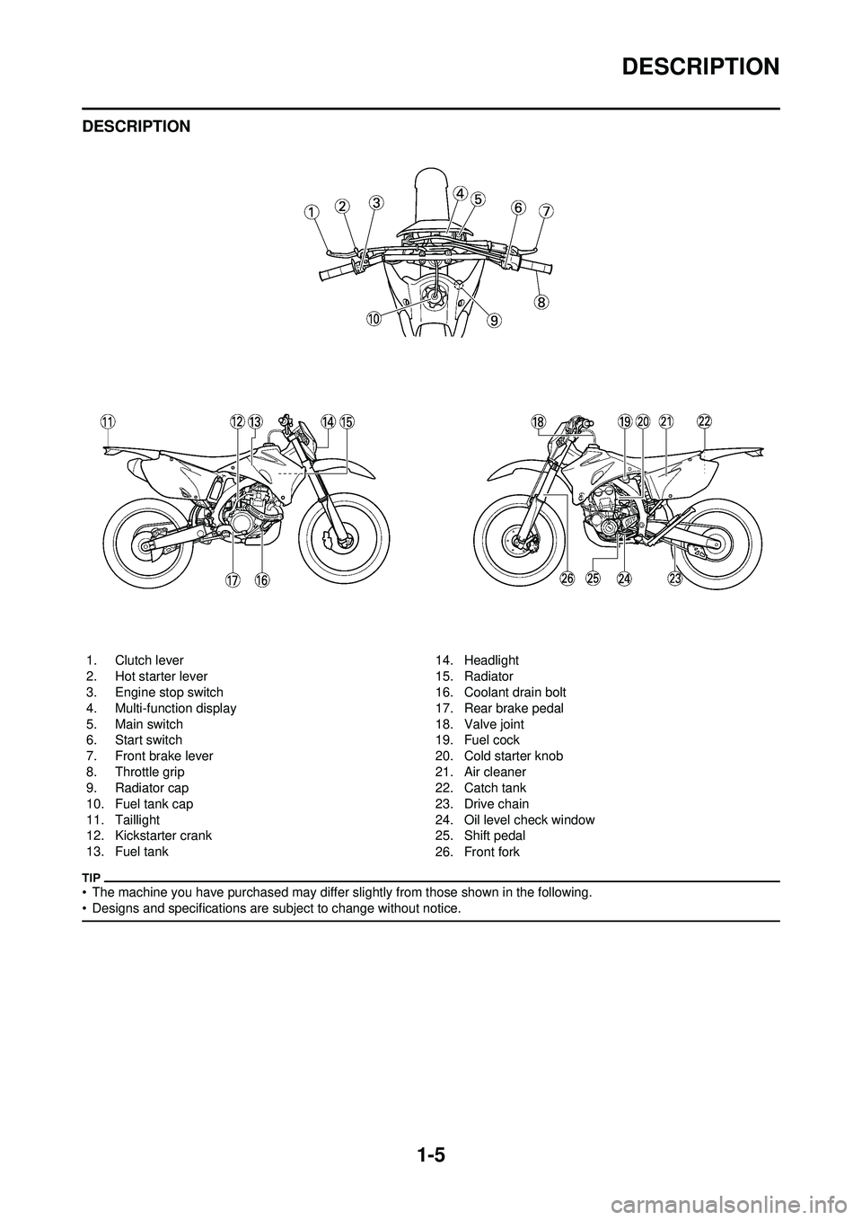
DESCRIPTION
• The machine you have purchased may differ slightly from those shown in the following.
• Designs and specifications are subject to change without notice.
1. Clutch lever
2. Hot starter lever
3. Engine stop switch
4. Multi-function display
5. Main switch
6. Start switch
7. Front brake lever
8. Throttle grip
9. Radiator cap
10. Fuel tank cap
11. Taillight
12. Kickstarter crank
13. Fuel tank 14. Headlight
15. Radiator
16. Coolant drain bolt
17. Rear brake pedal
18. Valve joint
19. Fuel cock
20. Cold starter knob
21. Air cleaner
22. Catch tank
23. Drive chain
24. Oil level check window
25. Shift pedal
26. Front fork
Page 28 of 232
1-18
STARTING AND BREAK-IN
STARTING AND BREAK-IN
FUEL
Always use the recommended fuel as
stated below. Also, be sure to use
new gasoline.
Use only unleaded gasoline. The
use of leaded gasoline will cause
severe damage to the engine inter-
nal parts such as valves, piston
rings, and exhaust system, etc.
If knocking or pinging occurs, use a
different brand of gasoline or higher
octane grade.
• For refueling, be sure to stop the
engine and use enough care not
to spill any fuel. Also be sure to
avoid refueling close to a fire.
• Refuel after the engine, exhaust pipe, etc. have cooled off.
Gasohol (For Canada)
There are two types of gasohol: gas-
ohol containing ethanol and that con-
taining methanol. Gasohol containing
ethanol can be used if the ethanol
content does not exceed 10%. Gaso-
hol containing methanol is not recom-
mended by Yamaha because it can
cause damage to the fuel system or
vehicle performance problems.
HANDLING NOTE
Never start or run the engine in a
closed area. The exhaust fumes
are poisonous; they can cause
loss of consciousness and death
in a very short time. Always oper-
ate the machine in a well-ventilated
area.
• The carburetor on this machine has a built-in accelerator pump.
Therefore, when starting the en-
gine, do not operate the throttle
or the spark plug will foul.
• Unlike a two-stroke engine, this engine cannot be kick started
when the throttl e is open be-
cause the kickstarter may kick
back. Also, if the throttle is open
the air/fuel mixture may be too
lean for the engine to start.
• Before starting the machine, per- form the checks in the pre-opera-
tion check list.
AIR FILTER MAINTENANCE
According to "CLEANING THE AIR
FILTER ELEMENT" section in the
CHAPTER 3, apply the foam-air-filter
oil or its equivalent to the element.
(Excess oil in the element may ad-
versely affect engine starting.)
STARTING A COLD ENGINE
This model is equipped with an igni-
tion circuit cut-off system. The engine
can be started under the following
conditions.
• When the transmission is in neutral.
• When the clutch is disengaged with
the transmission in any position.
However, it is recommended to shift
into neutral before starting the en-
gine.
1. Inspect the coolant level.
2. Turn the fuel cock to "ON".
3. Push on the main switch to "ON".
4. Shift the transmission into neutral.
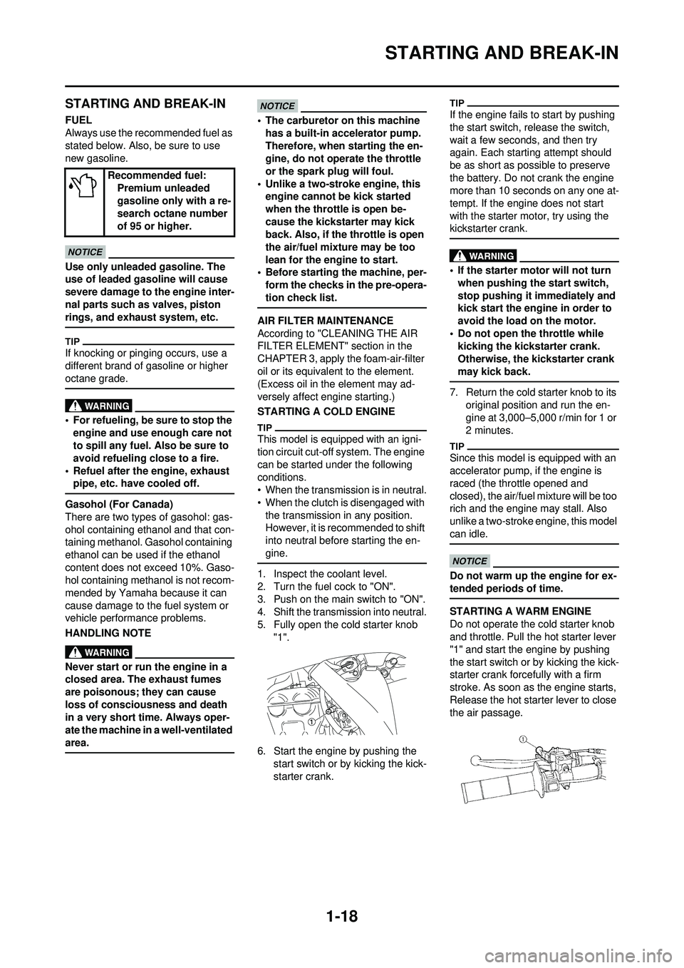
5. Fully open the cold starter knob "1".
6. Start the engine by pushing the start switch or by kicking the kick-
starter crank.
If the engine fails to start by pushing
the start switch, re lease the switch,
wait a few seconds, and then try
again. Each starting attempt should
be as short as possible to preserve
the battery. Do not crank the engine
more than 10 seconds on any one at-
tempt. If the engine does not start
with the starter motor, try using the
kickstarter crank.
• If the starter motor will no t turn
when pushing the start switch,
stop pushing it immediately and
kick start the engine in order to
avoid the load on the motor.
• Do not open the throttle while kicking the kickstarter crank.
Otherwise, the kickstarter crank
may kick back.
7. Return the cold starter knob to its original position and run the en-
gine at 3,000–5,000 r/min for 1 or
2 minutes.
Since this model is equipped with an
accelerator pump, if the engine is
raced (the throttle opened and
closed), the air/fuel mixture will be too
rich and the engine may stall. Also
unlike a two-stroke engine, this model
can idle.
Do not warm up th e engine for ex-
tended periods of time.
STARTING A WARM ENGINE
Do not operate the cold starter knob
and throttle. Pull the hot starter lever
"1" and start the engine by pushing
the start switch or by kicking the kick-
starter crank forcefully with a firm
stroke. As soon as the engine starts,
Release the hot starter lever to close
the air passage.
Recommended fuel:
Premium unleaded
gasoline only with a re-
search octane number
of 95 or higher.
Page 32 of 232
2-1
GENERAL SPECIFICATIONS
SPECIFICATIONS
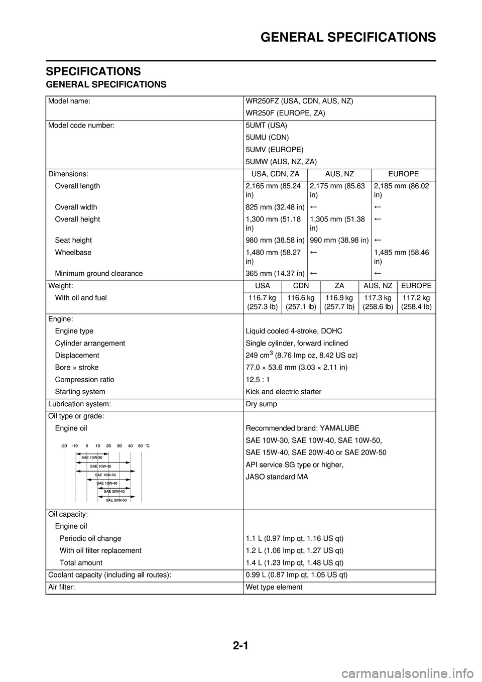
GENERAL SPECIFICATIONS
Model name:WR250FZ (USA, CDN, AUS, NZ)
WR250F (EUROPE, ZA)
Model code number: 5UMT (USA)
5UMU (CDN)
5UMV (EUROPE)
5UMW (AUS, NZ, ZA)
Dimensions: USA, CDN, ZA AUS, NZ EUROPE
Overall length 2,165 mm (85.24
in) 2,175 mm (85.63
in)2,185 mm (86.02
in)
Overall width 825 mm (32.48 in)←←
Overall height 1,300 mm (51.18
in) 1,305 mm (51.38
in)←
Seat height 980 mm (38.58 in) 990 mm (38.98 in)←
Wheelbase 1,480 mm (58.27
in) ←
1,485 mm (58.46
in)
Minimum ground clearance 365 mm (14.37 in)←←
Weight: USA CDN ZA AUS, NZ EUROPE
With oil and fuel 116.7 kg
(257.3 lb) 116.6 kg
(257.1 lb) 116.9 kg
(257.7 lb) 117.3 kg
(258.6 lb) 117.2 kg
(258.4 lb)
Engine: Engine type Liquid cooled 4-stroke, DOHC
Cylinder arrangement Single cylinder, forward inclined
Displacement 249 cm
3 (8.76 Imp oz, 8.42 US oz)
Bore × stroke 77.0 × 53.6 mm (3.03 × 2.11 in)
Compression ratio 12.5 : 1
Starting system Kick and electric starter
Lubrication system: Dry sump
Oil type or grade: Engine oil Recommended brand: YAMALUBE
SAE 10W-30, SAE 10W-40, SAE 10W-50,
SAE 15W-40, SAE 20W-40 or SAE 20W-50
API service SG type or higher,
JASO standard MA
Oil capacity: Engine oilPeriodic oil change 1.1 L (0.97 Imp qt, 1.16 US qt)
With oil filter replacement 1.2 L (1.06 Imp qt, 1.27 US qt)
Total amount 1.4 L (1.23 Imp qt, 1.48 US qt)
Coolant capacity (including all routes ):0.99 L (0.87 Imp qt, 1.05 US qt)
Air filter: Wet type element
Page 43 of 232
2-12
TIGHTENING TORQUES
TIGHTENING TORQUES
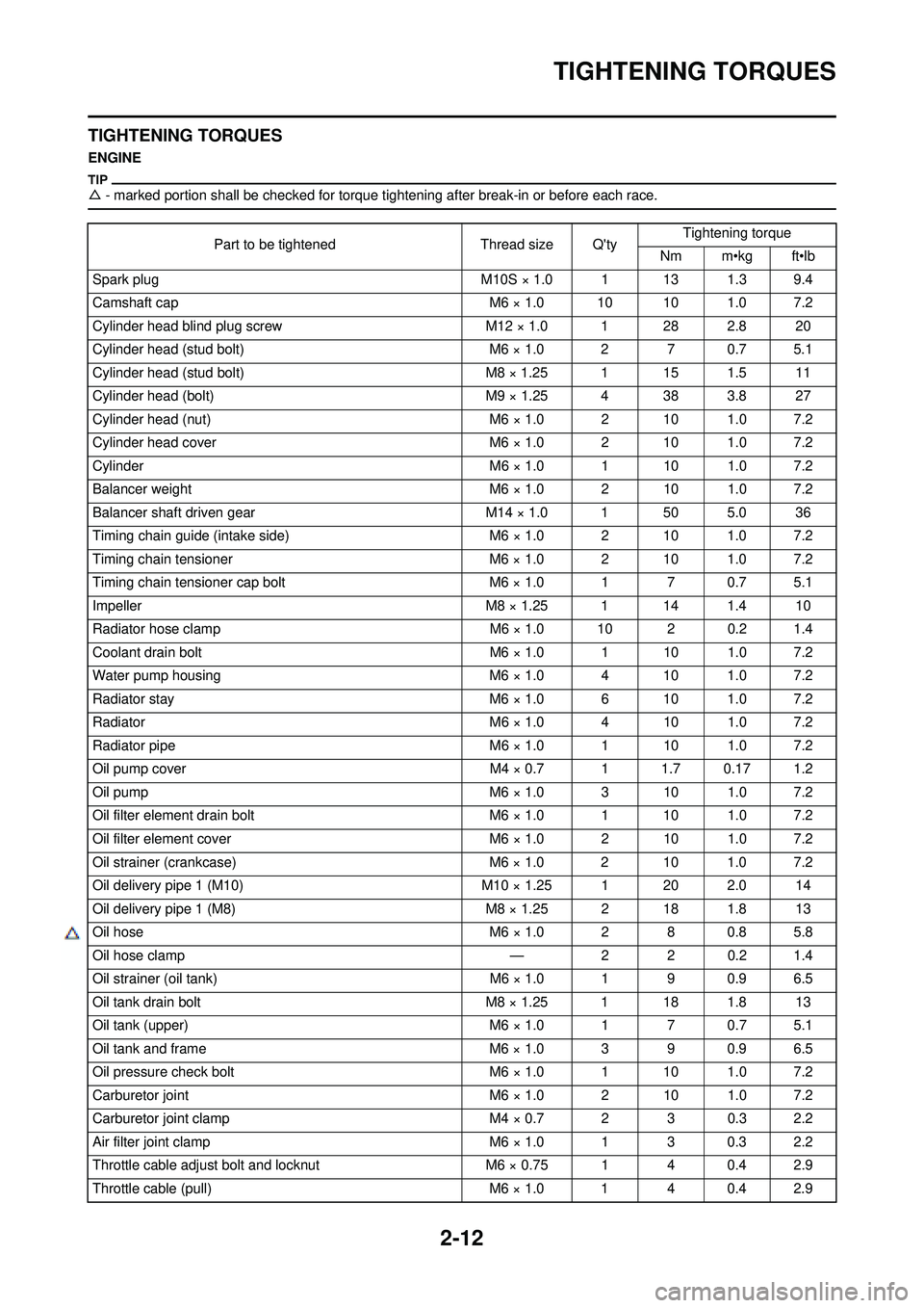
ENGINE
△- marked portion shall be checked for torque ti ghtening after break-in or before each race.
Part to be tightenedThread size Q'tyTightening torque
Nm m•kg ft•lb
Spark plug M10S × 1.0 1 13 1.3 9.4
Camshaft cap M6 × 1.0 10 10 1.0 7.2
Cylinder head blind plug screw M12 × 1.0 1 28 2.8 20
Cylinder head (stud bolt) M6 × 1.0 2 7 0.7 5.1
Cylinder head (stud bolt) M8 × 1.25 1 15 1.5 11
Cylinder head (bolt) M9 × 1.25 4 38 3.8 27
Cylinder head (nut) M6 × 1.0 2 10 1.0 7.2
Cylinder head cover M6 × 1.0 2 10 1.0 7.2
Cylinder M6 × 1.0 1 10 1.0 7.2
Balancer weight M6 × 1.0 2 10 1.0 7.2
Balancer shaft driven gear M14 × 1.0 1 50 5.0 36
Timing chain guide (intake side) M6 × 1.0 2 10 1.0 7.2
Timing chain tensioner M6 × 1.0 2 10 1.0 7.2
Timing chain tensioner cap bolt M6 × 1.0 1 7 0.7 5.1
Impeller M8 × 1.25 1 14 1.4 10
Radiator hose clamp M6 × 1.0 10 2 0.2 1.4
Coolant drain bolt M6 × 1.0 1 10 1.0 7.2
Water pump housing M6 × 1.0 4 10 1.0 7.2
Radiator stay M6 × 1.0 6 10 1.0 7.2
Radiator M6 × 1.0 4 10 1.0 7.2
Radiator pipe M6 × 1.0 1 10 1.0 7.2
Oil pump cover M4 × 0.7 1 1.7 0.17 1.2
Oil pump M6 × 1.0 3 10 1.0 7.2
Oil filter element drain bolt M6 × 1.0 1 10 1.0 7.2
Oil filter element cover M6 × 1.0 2 10 1.0 7.2
Oil strainer (crankcase) M6 × 1.0 2 10 1.0 7.2
Oil delivery pipe 1 (M10) M10 × 1.25 1 20 2.0 14
Oil delivery pipe 1 (M8) M8 × 1.25 2 18 1.8 13
Oil hose M6 × 1.0 2 8 0.8 5.8
△ Oil hose clamp —2 2 0.2 1.4
Oil strainer (oil tank) M6 × 1.0 1 9 0.9 6.5
Oil tank drain bolt M8 × 1.25 1 18 1.8 13
Oil tank (upper) M6 × 1.0 1 7 0.7 5.1
Oil tank and frame M6 × 1.0 3 9 0.9 6.5
Oil pressure check bolt M6 × 1.0 1 10 1.0 7.2
Carburetor joint M6 × 1.0 2 10 1.0 7.2
Carburetor joint clamp M4 × 0.7 2 3 0.3 2.2
Air filter joint clamp M6 × 1.0 1 3 0.3 2.2
Throttle cable adjust bolt and locknut M6 × 0.75 1 4 0.4 2.9
Throttle cable (pull) M6 × 1.0 1 4 0.4 2.9
Page 64 of 232
3-5
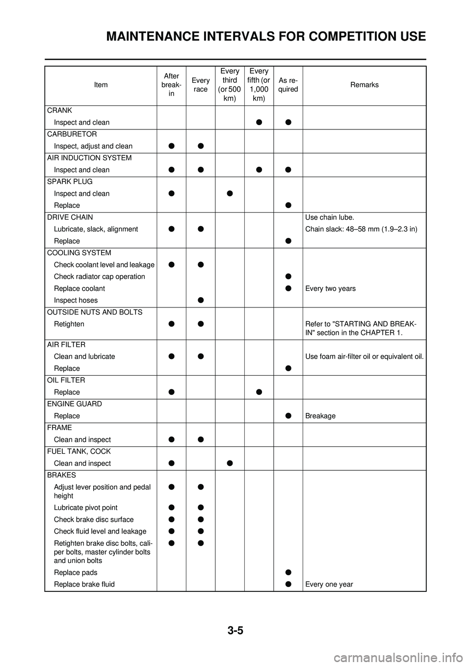
MAINTENANCE INTERVALS FOR COMPETITION USE
CRANKInspect and clean ●●
CARBURETOR Inspect, adjust and clean ●●
AIR INDUCTION SYSTEM Inspect and clean ●● ●●
SPARK PLUG Inspect and clean ●●
Replace ●
DRIVE CHAIN Use chain lube.
Lubricate, slack, alignment ●● Chain slack: 48–58 mm (1.9–2.3 in)
Replace ●
COOLING SYSTEM Check coolant level and leakage ●●
Check radiator cap operation ●
Replace coolant ●Every two years
Inspect hoses ●
OUTSIDE NUTS AND BOLTS Retighten ●● Refer to "STARTING AND BREAK-
IN" section in the CHAPTER 1.
AIR FILTER Clean and lubricate ●● Use foam air-filter oil or equivalent oil.
Replace ●
OIL FILTER Replace ●●
ENGINE GUARD Replace ●Breakage
FRAME Clean and inspect ●●
FUEL TANK, COCK Clean and inspect ●●
BRAKES Adjust lever position and pedal
height ●●
Lubricate pivot point ●●
Check brake disc surface ●●
Check fluid level and leakage ●●
Retighten brake disc bolts, cali-
per bolts, master cylinder bolts
and union bolts ●●
Replace pads ●
Replace brake fluid ●Every one year
Item
After
break- in Every
race
Every third
(or 500 km) Every
fifth (or
1,000 km)
As re-
quired Remarks
Page 66 of 232
3-7
PRE-OPERATION INSPECTION AND MAINTENANCE
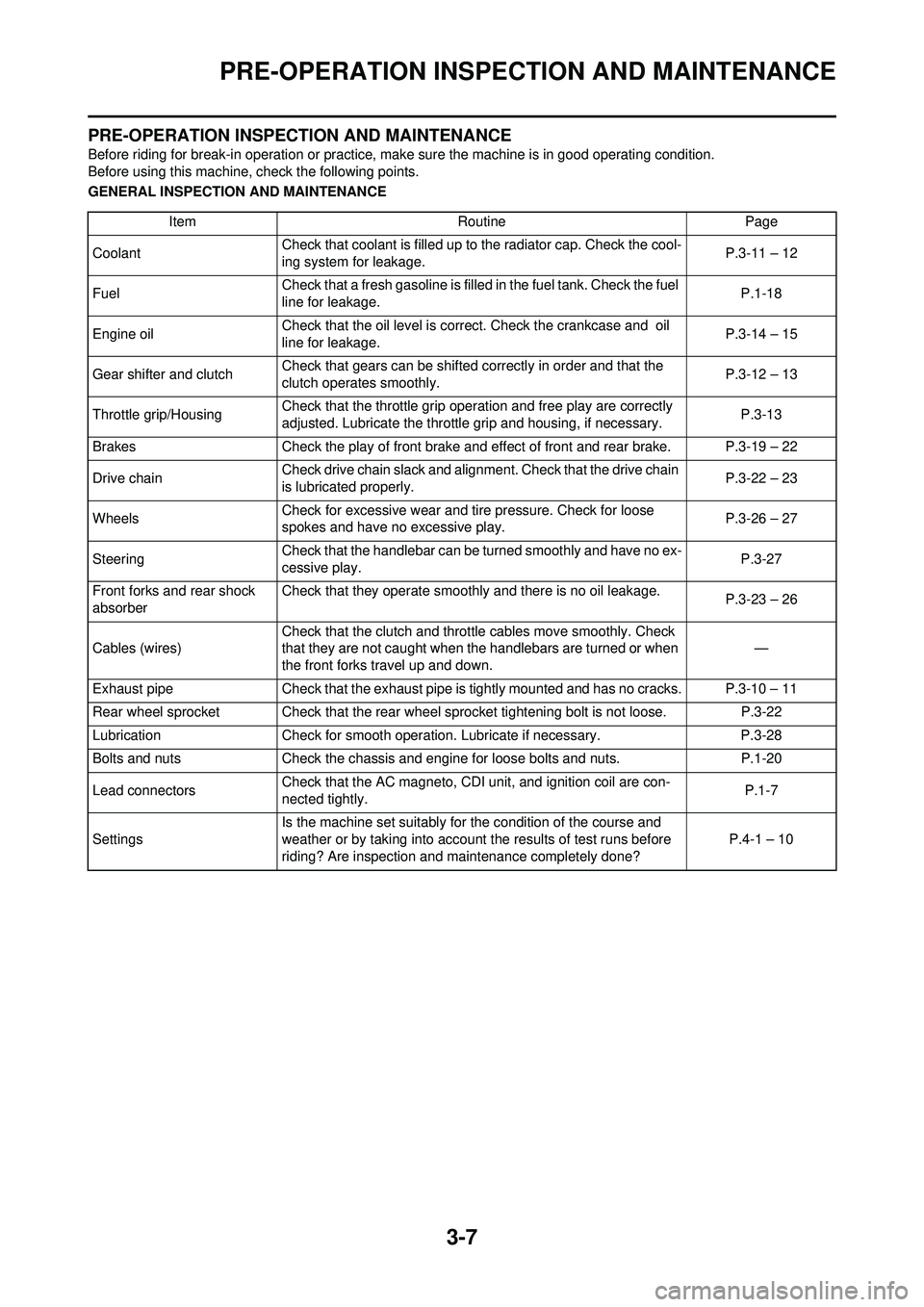
PRE-OPERATION INSPECTION AND MAINTENANCE
Before riding for break-in operation or practice, make sure the machine is in good operating condition.
Before using this machine, check the following points.
GENERAL INSPECTION AND MAINTENANCEItem RoutinePage
Coolant Check that coolant is filled up to the radiator cap. Check the cool-
ing system for leakage. P.3-11 – 12
Fuel Check that a fresh gasoline is filled in the fuel tank. Check the fuel
line for leakage.
P.1-18
Engine oil Check that the oil level is corre
ct. Check the crankcase and oil
line for leakage. P.3-14 – 15
Gear shifter and clutch Check that gears can be shifted correctly in order and that the
clutch operates smoothly. P.3-12 – 13
Throttle grip/Housing Check that the throttle grip operation and free play are correctly
adjusted. Lubricate the throttle grip and housing, if necessary.
P.3-13
Brakes Check the play of front brake and ef fect of front and rear brake. P.3-19 – 22
Drive chain Check drive chain slack and alignment. Check that the drive chain
is lubricated properly. P.3-22 – 23
Wheels Check for excessive wear and ti
re pressure. Check for loose
spokes and have no excessive play. P.3-26 – 27
Steering Check that the handlebar can be turned smoothly and have no ex-
cessive play.
P.3-27
Front forks and rear shock
absorber Check that they operate smoothly and there is no oil leakage.
P.3-23 – 26
Cables (wires) Check that the clutch and throttle cables move smoothly. Check
that they are not caught when the handlebars are turned or when
the front forks travel up and down. —
Exhaust pipe Check that the exhaust pipe is tightly mount ed and has no cracks. P.3-10 – 11
Rear wheel sprocket Check that the rear wheel sprocket tightening bolt is not loose. P.3-22
Lubrication Check for smooth operation. Lubricate if necessary. P.3-28
Bolts and nuts Check the chassis and engine for loose bolts and nuts. P.1-20
Lead connectors Check that the AC magneto, CDI unit, and ignition coil are con-
nected tightly. P.1-7
Settings Is the machine set suitably for the condition of the course and
weather or by taking into account the results of test runs before
riding? Are inspection and maintenance completely done? P.4-1 – 10
Page 70 of 232
3-11
ENGINE
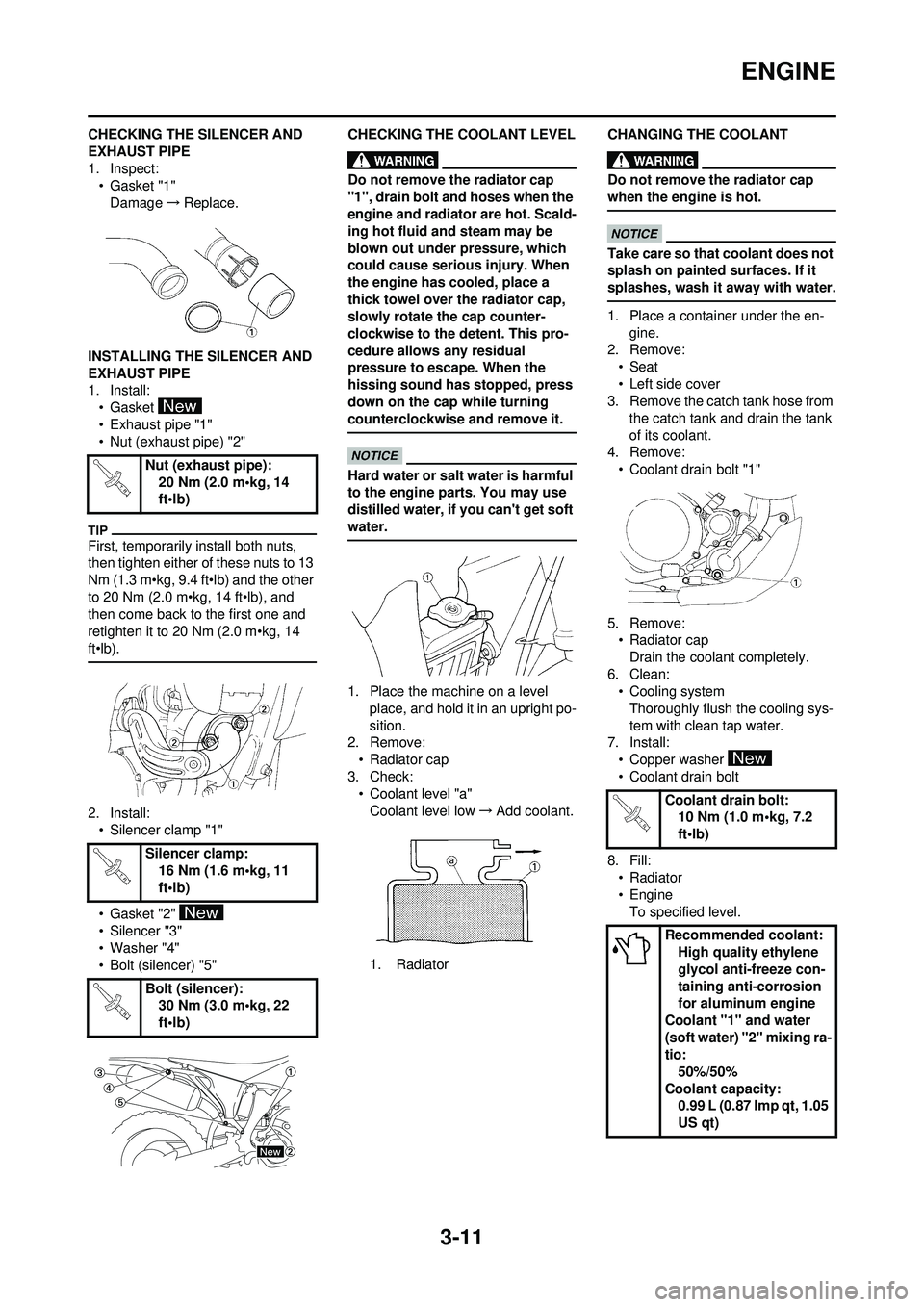
CHECKING THE SILENCER AND
EXHAUST PIPE
1. Inspect:• Gasket "1"
Damage →Replace.
INSTALLING THE SILENCER AND
EXHAUST PIPE
1. Install: • Gasket
• Exhaust pipe "1"
• Nut (exhaust pipe) "2"
First, temporarily install both nuts,
then tighten either of these nuts to 13
Nm (1.3 m•kg, 9.4 ft•lb) and the other
to 20 Nm (2.0 m•kg, 14 ft•lb), and
then come back to the first one and
retighten it to 20 Nm (2.0 m•kg, 14
ft•lb).
2. Install: • Silencer clamp "1"
• Gasket "2"
• Silencer "3"
• Washer "4"
• Bolt (silencer) "5" CHECKING THE COOLANT LEVEL
Do not remove the radiator cap
"1", drain bolt and hoses when the
engine and radiator are hot. Scald-
ing hot fluid and steam may be
blown out under pressure, which
could cause serious injury. When
the engine has cooled, place a
thick towel over the radiator cap,
slowly rotate the cap counter-
clockwise to the detent. This pro-
cedure allows any residual
pressure to escape. When the
hissing sound has stopped, press
down on the cap while turning
counterclockwise and remove it.
Hard water or salt water is harmful
to the engine parts. You may use
distilled water, if you can't get soft
water.
1. Place the machine on a level
place, and hold it in an upright po-
sition.
2. Remove: • Radiator cap
3. Check: • Coolant level "a"Coolant level low →Add coolant.
1. Radiator CHANGING THE COOLANT
Do not remove the radiator cap
when the engine is hot.
Take care so that coolant does not
splash on painted surfaces. If it
splashes, wash it away with water.
1. Place a container under the en-
gine.
2. Remove:
• Seat
• Left side cover
3. Remove the catch tank hose from
the catch tank and drain the tank
of its coolant.
4. Remove:
• Coolant drain bolt "1"
5. Remove: • Radiator capDrain the coolant completely.
6. Clean: • Cooling systemThoroughly flush the cooling sys-
tem with clean tap water.
7. Install: • Copper washer
• Coolant drain bolt
8. Fill: •Radiator
• Engine
To specified level.
Nut (exhaust pipe):
20 Nm (2.0 m•kg, 14
ft•lb)
Silencer clamp: 16 Nm (1.6 m•kg, 11
ft•lb)
Bolt (silencer): 30 Nm (3.0 m•kg, 22
ft•lb)
Coolant drain bolt:10 Nm (1.0 m•kg, 7.2
ft•lb)
Recommended coolant: High quality ethylene
glycol anti-freeze con-
taining anti-corrosion
for aluminum engine
Coolant "1" and water
(soft water) "2" mixing ra-
tio: 50%/50%
Coolant capacity: 0.99 L (0.87 Imp qt, 1.05
US qt)
Page 71 of 232
3-12
ENGINE
• Do not mix more than one type of ethylene glycol antifreeze con-
taining corrosion inhibitors for
aluminum engine.
• Do not use water containing im-
purities or oil.
Handling notes of coolant:
The coolant is harmful so it should be
handled with special care.
• When coolant splashes to your eye.
Thoroughly wash your eye with
water and see your doctor.
• When coolant splashes to your clothes.
Quickly wash it away with water
and then with soap.
• When coolant is swallowed. Quickly make him vomit and take
him to a doctor.
9. Install:• Radiator cap
Start the engine and warm it up
for a several minutes.
10. Check:
• Coolant levelCoolant level low →Add coolant.
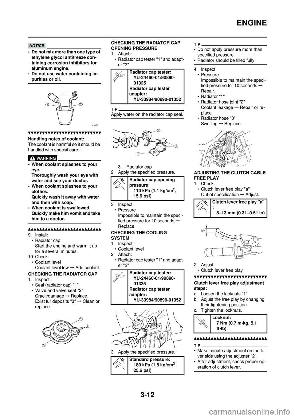
CHECKING THE RADIATOR CAP
1. Inspect: • Seal (radiator cap) "1"
• Valve and valve seat "2"Crack/damage →Replace.
Exist fur deposits "3" →Clean or
replace. CHECKING THE RADIATOR CAP
OPENING PRESSURE
1. Attach:
• Radiator cap tester "1" and adapt-
er "2"
Apply water on the radiator cap seal.
3. Radiator cap
2. Apply the specified pressure.
3. Inspect:
•PressureImpossible to maintain the speci-
fied pressure for 10 seconds →
Replace.
CHECKING THE COOLING
SYSTEM
1. Inspect: • Coolant level
2. Attach: • Radiator cap tester "1" and adapt-
er "2"
3. Apply the specified pressure.
• Do not apply pressure more than specified pressure.
• Radiator should be filled fully.
4. Inspect: • PressureImpossible to maintain the speci-
fied pressure for 10 seconds →
Repair.
•Radiator "1"
• Radiator hose joint "2"
Coolant leakage →Repair or re-
place.
• Radiator hose "3"
Swelling →Replace.
ADJUSTING THE CLUTCH CABLE
FREE PLAY
1. Check: • Clutch lever free play "a"Out of specification →Adjust.
2. Adjust: • Clutch lever free play
Clutch lever free play adjustment
steps:
a. Loosen the locknuts "1".
b. Adjust the free play by changing their tightening position.
c. Tighten the locknuts.
• Make minute adjustment on the le- ver side using the adjuster "2".
• After adjustment, check proper op- eration of clutch lever.
Radiator cap tester: YU-24460-01/90890-
01325
Radiator cap tester
adapter: YU-33984/90890-01352
Radiator cap opening
pressure: 110 kPa (1.1 kg/cm
2,
15.6 psi)
Radiator cap tester: YU-24460-01/90890-
01325
Radiator cap tester
adapter: YU-33984/90890-01352
Standard pressure: 180 kPa (1.8 kg/cm
2,
25.6 psi)
Clutch lever free play "a"
: 8–13 mm (0.31–0.51 in)
Locknut: 7 Nm (0.7 m•kg, 5.1
ft•lb)
Page 75 of 232
3-16
ENGINE
ADJUSTING THE PILOT SCREW
(For EUROPE)
1. Adjust:• Pilot screw "1"
Adjustment steps:
To optimize the fuel flow at a smaller
throttle opening, each machine's pilot
screw has been individually set at the
factory. Before adjusting the pilot
screw, turn it in fully and count the
number of turns. Record this number
as the factory-set number of turns
out.
a. Turn in the pilot screw until it is lightly seated.
b. Turn out the pilot screw by the factory-set number of turns.
ADJUSTING THE ENGINE IDLING
SPEED
1. Start the engine and thoroughly warm it up.
2. Adjust: • Engine idling speed
Adjustment steps:
a. Turn the throttle stop screw "1" until the specified engine idling
speed.
Using a digital engine tachometer for
idle speed adjustment, detect the en-
gine idling speed by bringing the
sensing element "c" of the engine ta-
chometer close to the ignition coil "2".
ADJUSTING THE VALVE
CLEARANCE
This section is intended for those who
have basic knowledge and skill con-
cerning the servicing of Yamaha mo-
torcycles (e.g., Yamaha dealers,
service engineers, etc.) Those who
have little knowledge and skill con-
cerning servicing are requested not to
undertake inspection, adjustment,
disassembly, or reassembly only by
reference to this manual. It may lead
to servicing trouble and mechanical
damage.
• The valve clearance should be ad-justed when the engine is cool to
the touch.
• The piston must be at Top Dead Center (T.D.C.) on compression
stroke to check or adjust the valve
clearance.
1. Remove:•Seat
•Fuel tank
Refer to "SEAT, FUEL TANK
AND SIDE COVERS" section.
2. Drain:
• CoolantRefer to "CHANGING THE
COOLANT" section.
3. Remove: • Right radiatorRight to "RADIATOR" section in
the CHAPTER 5.
• Carburetor Refer to "CARBU RETOR" section
in the CHAPTER 5.
• Spark plug
• Upper engine bracket
• Cylinder head cover Refer to "CAMSHAFTS" section
in the CHAPTER 5. 4. Remove:
• Timing mark accessing screw "1"
• Crankshaft end accessing screw "2"
• O-ring
5. Check: • Valve clearanceOut of specification →Adjust.
Checking steps:
a. Turn the crankshaft counterclock-
wise with a wrench.
b. Align the T.D.C. mark "a" on the
rotor with the align mark "b" on the
crankcase cover when piston is at
T.D.C. on compression stroke.
In order to be sure t hat the piston is at
Top Dead Center, the punch mark "c"
on the exhaust camshaft and the
punch mark "d" on the intake cam-
shaft must align with the cylinder
head surface, as shown in the illustra-
tion.
c. Measure the valve clearance "e" using a feeler gauge "1".
Record the measured reading if the
clearance is incorrect.
Pilot screw (example):2 turns out
To increase idle speed →Turn the
throttle stop screw "1" in "a".
To decrease idle speed →Turn the
throttle stop screw "1" out "b".
Engine idling speed:1,750–1,950 r/min
Valve clearance (cold):
Intake valve:0.10–0.15 mm
(0.0039–0.0059 in)
Exhaust valve:0.17–0.22 mm
(0.0067–0.0087 in)
Page 104 of 232
5-1
RADIATOR
ENGINE
This section is intended for those who have basic knowledge and skill concerning the servicing of Yamaha motorcycles
(e.g., Yamaha dealers, service engineers, etc.) Those who have little knowledge and skill concerning servicing are request-
ed not to undertake inspection, adjustment, disassembly, or reassembly only by reference to this manual. It may lead to
servicing trouble and mechanical damage.
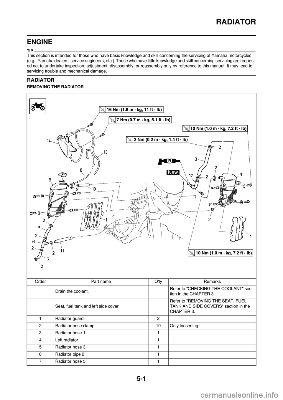
RADIATOR
REMOVING THE RADIATOR
Order Part name Q'ty Remarks Drain the coolant. Refer to "CHECKING THE COOLANT" sec-
tion in the CHAPTER 3.
Seat, fuel tank and left side cover Refer to "REMOVING THE SEAT, FUEL
TANK AND SIDE COVERS" section in the
CHAPTER 3.
1 Radiator guard 2
2 Radiator hose clamp 10 Only loosening.
3 Radiator hose 1 1
4 Left radiator 1
5 Radiator hose 3 1
6 Radiator pipe 2 1
7 Radiator hose 5 1