set clock YAMAHA WR 250F 2010 Owners Manual
[x] Cancel search | Manufacturer: YAMAHA, Model Year: 2010, Model line: WR 250F, Model: YAMAHA WR 250F 2010Pages: 232, PDF Size: 13.94 MB
Page 23 of 232
1-13
MULTI-FUNCTION DISPLAY
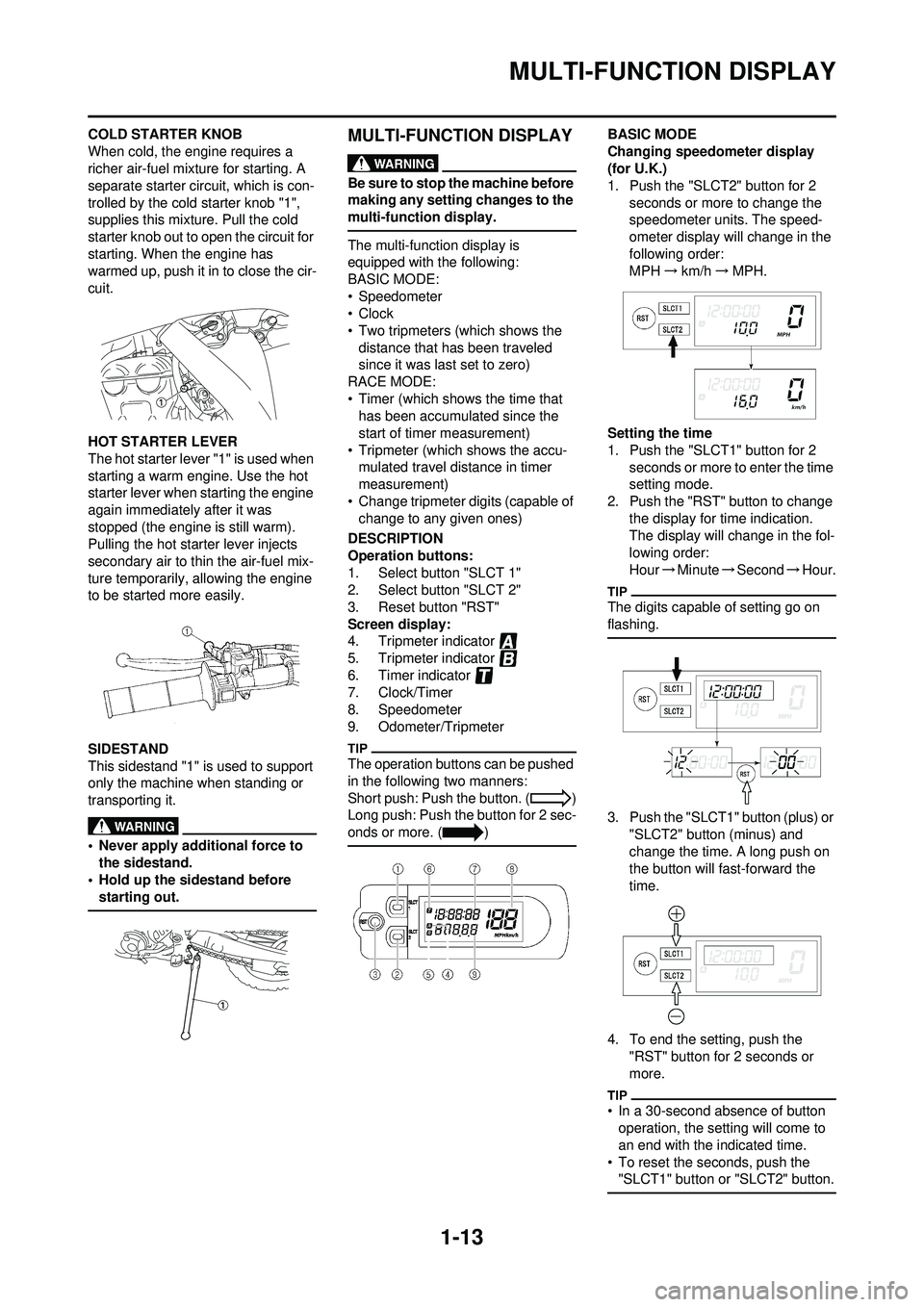
COLD STARTER KNOB
When cold, the engine requires a
richer air-fuel mixture for starting. A
separate starter circuit, which is con-
trolled by the cold starter knob "1",
supplies this mixture. Pull the cold
starter knob out to open the circuit for
starting. When the engine has
warmed up, push it in to close the cir-
cuit.
HOT STARTER LEVER
The hot starter lever "1" is used when
starting a warm engine. Use the hot
starter lever when starting the engine
again immediately after it was
stopped (the engine is still warm).
Pulling the hot starter lever injects
secondary air to thin the air-fuel mix-
ture temporarily, allowing the engine
to be started more easily.
SIDESTAND
This sidestand "1" is used to support
only the machine when standing or
transporting it.
• Never apply additional force to the sidestand.
• Hold up the sidestand before
starting out.
MULTI-FUNCTION DISPLAY
Be sure to stop the machine before
making any setting changes to the
multi-function display.
The multi-function display is
equipped with the following:
BASIC MODE:
• Speedometer
•Clock
• Two tripmeters (which shows the distance that has been traveled
since it was last set to zero)
RACE MODE:
• Timer (which shows the time that has been accumulated since the
start of timer measurement)
• Tripmeter (which shows the accu- mulated travel distance in timer
measurement)
• Change tripmeter digits (capable of change to any given ones)
DESCRIPTION
Operation buttons:
1. Select button "SLCT 1"
2. Select button "SLCT 2"
3. Reset button "RST"
Screen display:
4. Tripmeter indicator
5. Tripmeter indicator
6. Timer indicator
7. Clock/Timer
8. Speedometer
9. Odometer/Tripmeter
The operation buttons can be pushed
in the following two manners:
Short push: Push the button. ( )
Long push: Push the button for 2 sec-
onds or more. ( )
BASIC MODE
Changing speedometer display
(for U.K.)
1. Push the "SLCT2" button for 2 seconds or more to change the
speedometer units. The speed-
ometer display will change in the
following order:
MPH →km/h →MPH.
Setting the time
1. Push the "SLCT1" button for 2 seconds or more to enter the time
setting mode.
2. Push the "RST" button to change the display for time indication.
The display will change in the fol-
lowing order:
Hour →Minute →Second →Hour.
The digits capable of setting go on
flashing.
3. Push the "SLCT1" button (plus) or
"SLCT2" button (minus) and
change the time. A long push on
the button will fast-forward the
time.
4. To end the setting, push the "RST" button for 2 seconds or
more.
• In a 30-second absence of button operation, the setting will come to
an end with the indicated time.
• To reset the seconds, push the "SLCT1" button or "SLCT2" button.
Page 26 of 232
1-16
MULTI-FUNCTION DISPLAY
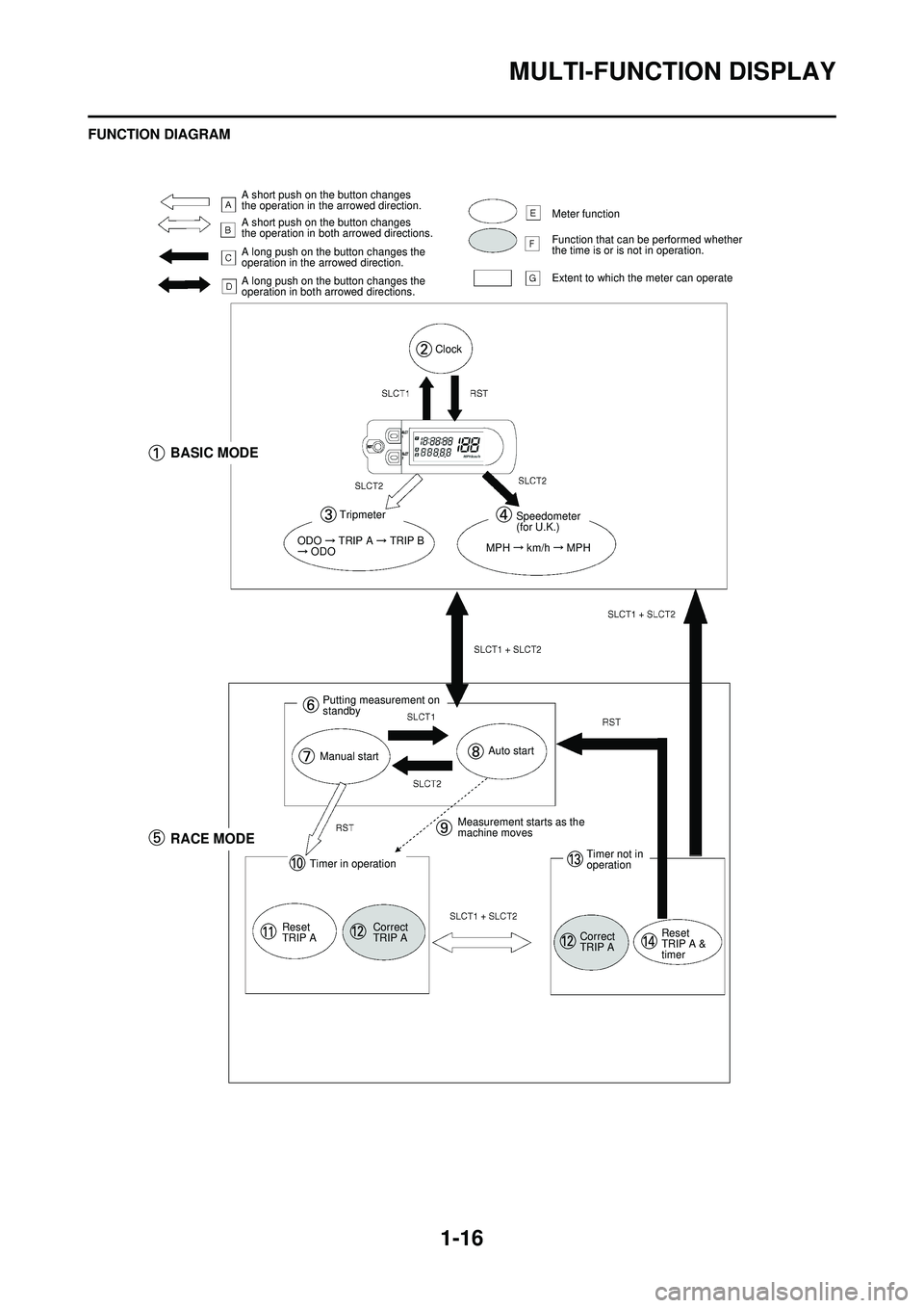
FUNCTION DIAGRAM
A short push on the button changes
the operation in the arrowed direction.
A short push on the button changes
the operation in both arrowed directions.
A long push on the button changes the
operation in the arrowed direction.
A long push on the button changes the
operation in both arrowed directions.Meter function
Function that can be performed whether
the time is or is not in operation.
Extent to which the meter can operate
Clock
BASIC MODE
Tripmeter
ODO TRIP A TRIP B ODO
Speedometer
(for U.K.)
MPH
km/h MPH
Putting measurement on
standby
Manual startAuto start
RACE MODE
Timer in operation
Reset
TRIP A Correct
TRIP AMeasurement starts as the
machine moves
Timer not in
operation
Correct
TRIP A Reset
TRIP A &
timer
Page 27 of 232
1-17
MULTI-FUNCTION DISPLAY
The following diagram illustrates the
multi-function display regarding the
direction and operation condition in-
volved in each of its functions.
A. A short push on the button changes the operation in the ar-
rowed direction.
B. A short push on the button changes the operation in both
arrowed directions.
C. A long push on the button changes the operation in the ar-
rowed direction.
D. A long push on the button changes the operation in both
arrowed directions.
E. Meter function
F. Function that can be performed whether the time is or is not in
operation.
G. Extent to which the meter can operate
1. BASIC MODE
2. Clock
3. Trip meter
4. Speedometer (for U.K.)
5. RACE MODE
6. Putting measurement on stand-
by
7. Manual start
8. Auto start
9. Measurement starts as the ma- chine moves
10. Timer in operation
11. Reset TRIP A
12. Correct TRIP A
13. Timer not in operation
14. Reset TRIP A & timer
Page 37 of 232
2-6
MAINTENANCE SPECIFICATIONS
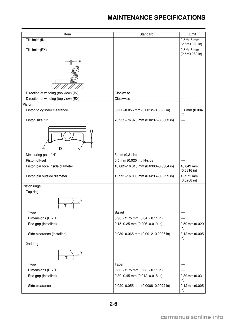
Tilt limit* (IN)----2.5°/1.6 mm
(2.5°/0.063 in)
Tilt limit* (EX) ----2.5°/1.6 mm
(2.5°/0.063 in)
Direction of winding (top view) (IN) Clockwise----
Direction of winding (top view) (EX) Clockwise----
Piston: Piston to cylinder clearance 0.030–0.055 mm (0.0012–0.0022 in) 0.1 mm (0.004
in)
Piston size "D" 76.955–76.970 mm (3.0297–3.0303 in) ----
Measuring point "H " 8 mm (0.31 in) ----
Piston off-set 0.5 mm (0.020 in)/IN-side ----
Piston pin bore inside diameter 16.002–16.013 mm (0.6300–0.6304 in) 16.043 mm
(0.6316 in)
Piston pin outside diameter 15.991–16.000 mm (0.6296–0.6299 in) 15.971 mm
(0.6288 in)
Piston rings: Top ring:
Type Barrel----
Dimensions (B × T) 0.90 × 2.75 mm (0.04 × 0.11 in)----
End gap (installed) 0.15–0.25 mm (0.006–0.010 in) 0.50 mm (0.020
in)
Side clearance (installed) 0.030–0.065 mm (0.0012–0.0026 in) 0.12 mm (0.005
in)
2nd ring:
Type Taper----
Dimensions (B × T) 0.80 × 2.75 mm (0.03 × 0.11 in)----
End gap (installed) 0.30–0.45 mm (0.012–0.018 in) 0.80 mm (0.031
in)
Side clearance 0.020–0.055 mm (0.0008–0.0022 in) 0.12 mm (0.005
in)
Item
StandardLimit
Page 75 of 232
3-16
ENGINE
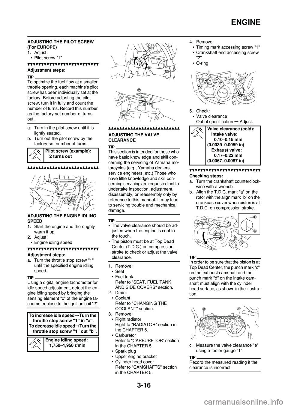
ADJUSTING THE PILOT SCREW
(For EUROPE)
1. Adjust:• Pilot screw "1"
Adjustment steps:
To optimize the fuel flow at a smaller
throttle opening, each machine's pilot
screw has been individually set at the
factory. Before adjusting the pilot
screw, turn it in fully and count the
number of turns. Record this number
as the factory-set number of turns
out.
a. Turn in the pilot screw until it is lightly seated.
b. Turn out the pilot screw by the factory-set number of turns.
ADJUSTING THE ENGINE IDLING
SPEED
1. Start the engine and thoroughly warm it up.
2. Adjust: • Engine idling speed
Adjustment steps:
a. Turn the throttle stop screw "1" until the specified engine idling
speed.
Using a digital engine tachometer for
idle speed adjustment, detect the en-
gine idling speed by bringing the
sensing element "c" of the engine ta-
chometer close to the ignition coil "2".
ADJUSTING THE VALVE
CLEARANCE
This section is intended for those who
have basic knowledge and skill con-
cerning the servicing of Yamaha mo-
torcycles (e.g., Yamaha dealers,
service engineers, etc.) Those who
have little knowledge and skill con-
cerning servicing are requested not to
undertake inspection, adjustment,
disassembly, or reassembly only by
reference to this manual. It may lead
to servicing trouble and mechanical
damage.
• The valve clearance should be ad-justed when the engine is cool to
the touch.
• The piston must be at Top Dead Center (T.D.C.) on compression
stroke to check or adjust the valve
clearance.
1. Remove:•Seat
•Fuel tank
Refer to "SEAT, FUEL TANK
AND SIDE COVERS" section.
2. Drain:
• CoolantRefer to "CHANGING THE
COOLANT" section.
3. Remove: • Right radiatorRight to "RADIATOR" section in
the CHAPTER 5.
• Carburetor Refer to "CARBU RETOR" section
in the CHAPTER 5.
• Spark plug
• Upper engine bracket
• Cylinder head cover Refer to "CAMSHAFTS" section
in the CHAPTER 5. 4. Remove:
• Timing mark accessing screw "1"
• Crankshaft end accessing screw "2"
• O-ring
5. Check: • Valve clearanceOut of specification →Adjust.
Checking steps:
a. Turn the crankshaft counterclock-
wise with a wrench.
b. Align the T.D.C. mark "a" on the
rotor with the align mark "b" on the
crankcase cover when piston is at
T.D.C. on compression stroke.
In order to be sure t hat the piston is at
Top Dead Center, the punch mark "c"
on the exhaust camshaft and the
punch mark "d" on the intake cam-
shaft must align with the cylinder
head surface, as shown in the illustra-
tion.
c. Measure the valve clearance "e" using a feeler gauge "1".
Record the measured reading if the
clearance is incorrect.
Pilot screw (example):2 turns out
To increase idle speed →Turn the
throttle stop screw "1" in "a".
To decrease idle speed →Turn the
throttle stop screw "1" out "b".
Engine idling speed:1,750–1,950 r/min
Valve clearance (cold):
Intake valve:0.10–0.15 mm
(0.0039–0.0059 in)
Exhaust valve:0.17–0.22 mm
(0.0067–0.0087 in)
Page 92 of 232
3-33
ELECTRICAL
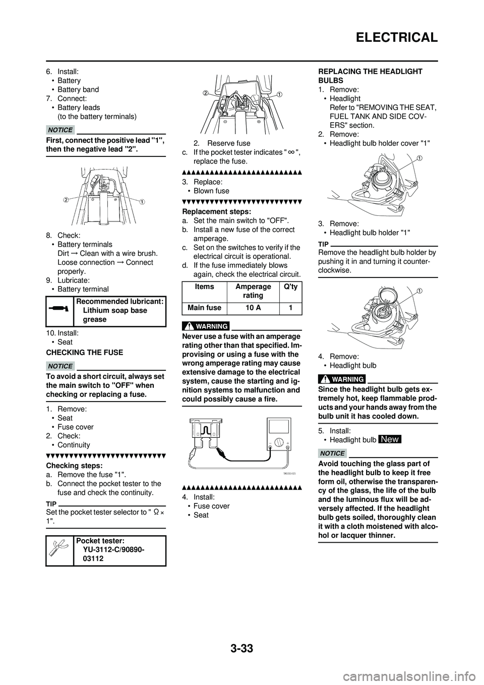
6. Install:•Battery
• Battery band
7. Connect:
• Battery leads(to the battery terminals)
First, connect the positive lead "1",
then the negative lead "2".
8. Check:• Battery terminals
Dirt →Clean with a wire brush.
Loose connection →Connect
properly.
9. Lubricate: • Battery terminal
10. Install: • Seat
CHECKING THE FUSE
To avoid a short circuit, always set
the main switch to "OFF" when
checking or replacing a fuse.
1. Remove: • Seat
• Fuse cover
2. Check:
• Continuity
Checking steps:
a. Remove the fuse "1".
b. Connect the pocket tester to the fuse and check the continuity.
Set the pocket tester selector to " Ω×
1".
2. Reserve fuse
c. If the pocket test er indicates "∞",
replace the fuse.
3. Replace: • Blown fuse
Replacement steps:
a. Set the main switch to "OFF".
b. Install a new fuse of the correct amperage.
c. Set on the switches to verify if the electrical circuit is operational.
d. If the fuse immediately blows again, check the electrical circuit.
Never use a fuse with an amperage
rating other than th at specified. Im-
provising or using a fuse with the
wrong amperage rating may cause
extensive damage to the electrical
system, cause the starting and ig-
nition systems to malfunction and
could possibly cause a fire.
4. Install: • Fuse cover
•Seat REPLACING THE HEADLIGHT
BULBS
1. Remove:
• Headlight
Refer to "REMOVING THE SEAT,
FUEL TANK AND SIDE COV-
ERS" section.
2. Remove: • Headlight bulb holder cover "1"
3. Remove: • Headlight bulb holder "1"
Remove the headlight bulb holder by
pushing it in and turning it counter-
clockwise.
4. Remove:• Headlight bulb
Since the headlight bulb gets ex-
tremely hot, keep flammable prod-
ucts and your hands away from the
bulb unit it has cooled down.
5. Install:• Headlight bulb
Avoid touching the glass part of
the headlight bulb to keep it free
form oil, otherwis e the transparen-
cy of the glass, the life of the bulb
and the luminous flux will be ad-
versely affected. If the headlight
bulb gets soiled, thoroughly clean
it with a cloth moistened with alco-
hol or lacquer thinner.
Recommended lubricant: Lithium soap base
grease
Pocket tester: YU-3112-C/90890-
03112
Items Amperage ratingQ'ty
Main fuse 10 A 1
Page 102 of 232
4-9
CHASSIS
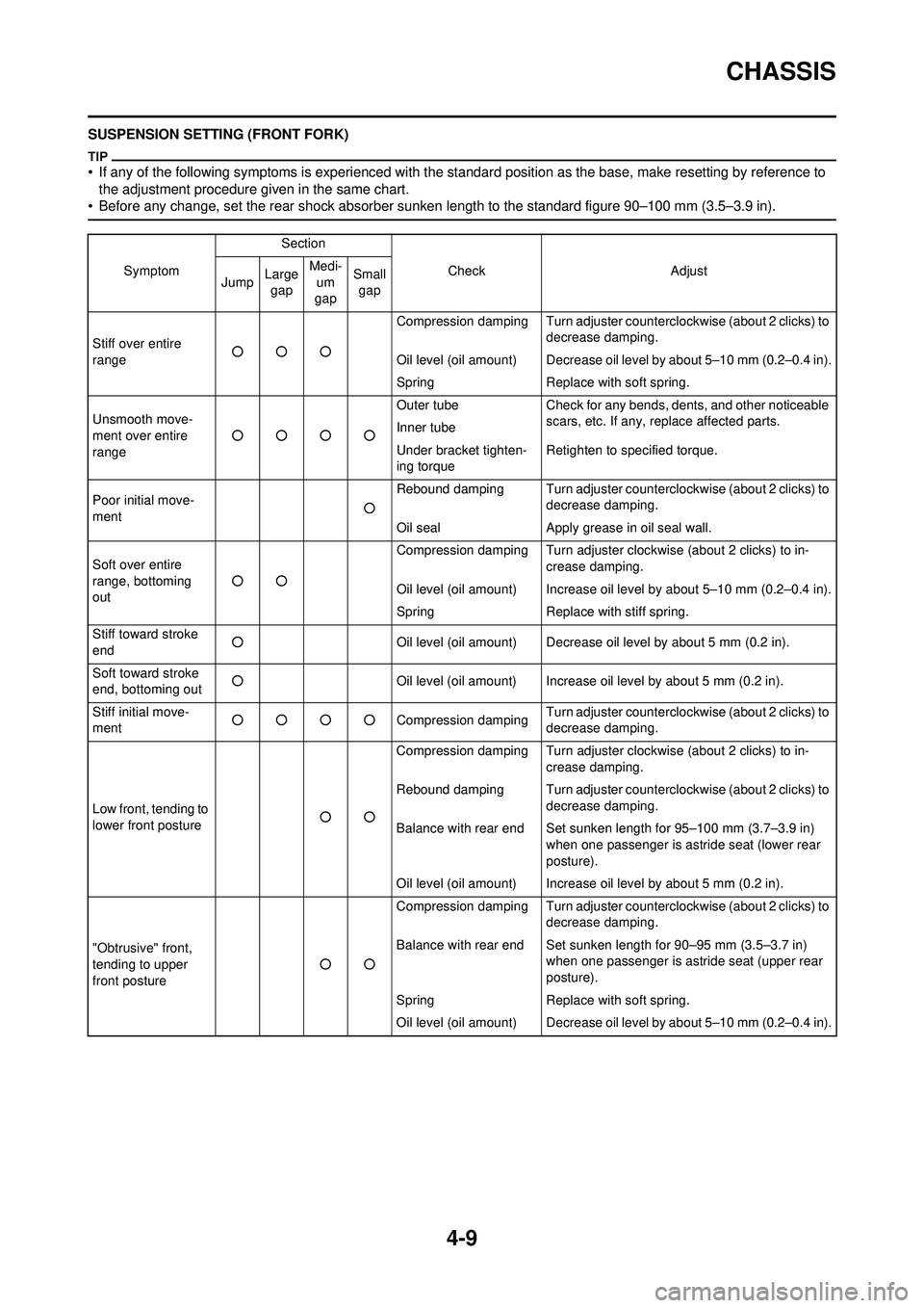
SUSPENSION SETTING (FRONT FORK)
• If any of the following symptoms is experienced with the standard position as the base, make resetting by reference to the adjustment procedure gi ven in the same chart.
• Before any change, set t he rear shock absorber sunken length to the standard figure 90–100 mm (3.5–3.9 in).
SymptomSection
Check Adjust
Jump Large
gap Medi-
um
gap Small
gap
Stiff over entire
range ○○○ Compression damping Turn adjuster counterclockwise (about 2 clicks) to
decrease damping.
Oil level (oil amount) Decrease oil level by about 5–10 mm (0.2–0.4 in).
Spring Replace with soft spring.
Unsmooth move-
ment over entire
range ○○○○ Outer tube
Check for any bends, dents, and other noticeable
scars, etc. If any, replace affected parts.
Inner tube
Under bracket tighten-
ing torque Retighten to specified torque.
Poor initial move-
ment ○Rebound damping Turn adjuster counterclockwise (about 2 clicks) to
decrease damping.
Oil seal Apply grease in oil seal wall.
Soft over entire
range, bottoming
out ○○ Compression damping Turn adjuster clockwise (about 2 clicks) to in-
crease damping.
Oil level (oil amount) Increase oil level by about 5–10 mm (0.2–0.4 in).
Spring Replace with stiff spring.
Stiff toward stroke
end ○
Oil level (oil amount) Decrease oil level by about 5 mm (0.2 in).
Soft toward stroke
end, bottoming out ○
Oil level (oil amount) Increase oil level by about 5 mm (0.2 in).
Stiff initial move-
ment ○○○○
Compression dampingTurn adjuster counterclockwise (about 2 clicks) to
decrease damping.
Low front, tending to
lower front posture ○○Compression damping Turn adjuster clockwise (about 2 clicks) to in-
crease damping.
Rebound damping Turn adjuster counterclockwise (about 2 clicks) to decrease damping.
Balance with rear end Set sunken length for 95–100 mm (3.7–3.9 in) when one passenger is astride seat (lower rear
posture).
Oil level (oil amount) Increase oil level by about 5 mm (0.2 in).
"Obtrusive" front,
tending to upper
front posture ○○Compression damping Turn adjuster counterclockwise (about 2 clicks) to
decrease damping.
Balance with rear end Set sunken length for 90–95 mm (3.5–3.7 in) when one passenger is astride seat (upper rear
posture).
Spring Replace with soft spring.
Oil level (oil amount) Decrease oil level by about 5–10 mm (0.2–0.4 in).
Page 103 of 232
4-10
CHASSIS
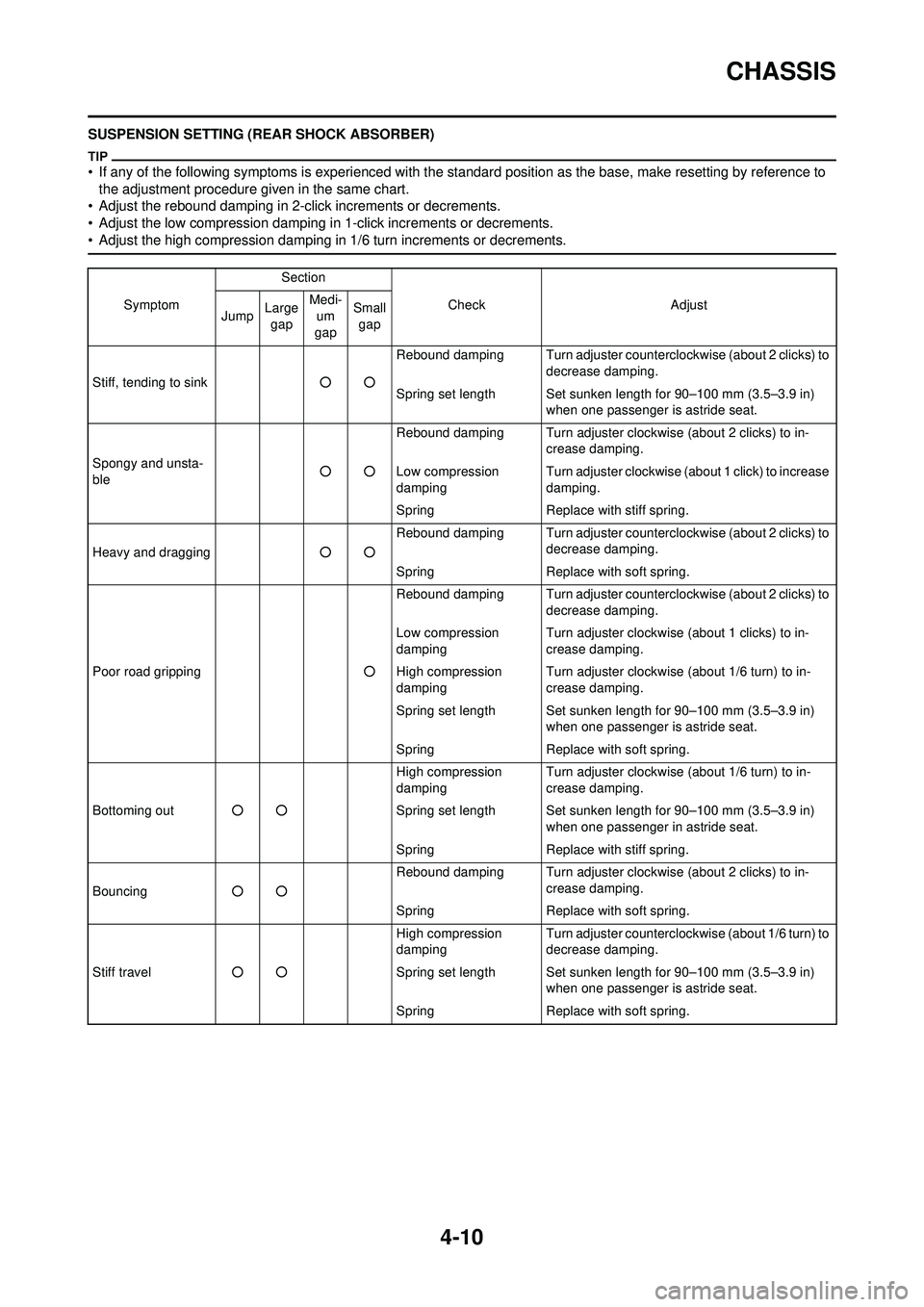
SUSPENSION SETTING (REAR SHOCK ABSORBER)
• If any of the following symptoms is experienced with the standard position as the base, make resetting by reference to the adjustment procedure gi ven in the same chart.
• Adjust the rebound damping in 2-click increments or decrements.
• Adjust the low compression damping in 1-click increments or decrements.
• Adjust the high compression damping in 1/6 turn increments or decrements.
Symptom Section
Check Adjust
Jump Large
gap Medi-
um
gap Small
gap
Stiff, tending to sink ○○Rebound damping Turn adjuster counterclockwise (about 2 clicks) to
decrease damping.
Spring set length Set sunken length for 90–100 mm (3.5–3.9 in) when one passenger is astride seat.
Spongy and unsta-
ble ○○Rebound damping Turn adjuster clockwise (about 2 clicks) to in-
crease damping.
Low compression
damping Turn adjuster clockwise (about 1 click) to increase
damping.
Spring Replace with stiff spring.
Heavy and dragging ○○Rebound damping Turn adjuster counterclockwise (about 2 clicks) to
decrease damping.
Spring Replace with soft spring.
Poor road gripping ○Rebound damping Turn adjuster counterclockwise (about 2 clicks) to
decrease damping.
Low compression
damping Turn adjuster clockwise (about 1 clicks) to in-
crease damping.
High compression
damping Turn adjuster clockwise (about 1/6 turn) to in-
crease damping.
Spring set length Set sunken length for 90–100 mm (3.5–3.9 in) when one passenger is astride seat.
Spring Replace with soft spring.
Bottoming out ○○ High compression
damping
Turn adjuster clockwise (about 1/6 turn) to in-
crease damping.
Spring set length Set sunken length for 90–100 mm (3.5–3.9 in) when one passenger in astride seat.
Spring Replace with stiff spring.
Bouncing ○○ Rebound damping Turn adjuster clockwise (about 2 clicks) to in-
crease damping.
Spring Replace with soft spring.
Stiff travel ○○ High compression
damping
Turn adjuster counterclockw
ise (about 1/6 turn) to
decrease damping.
Spring set length Set sunken length for 90–100 mm (3.5–3.9 in) when one passenger is astride seat.
Spring Replace with soft spring.
Page 120 of 232
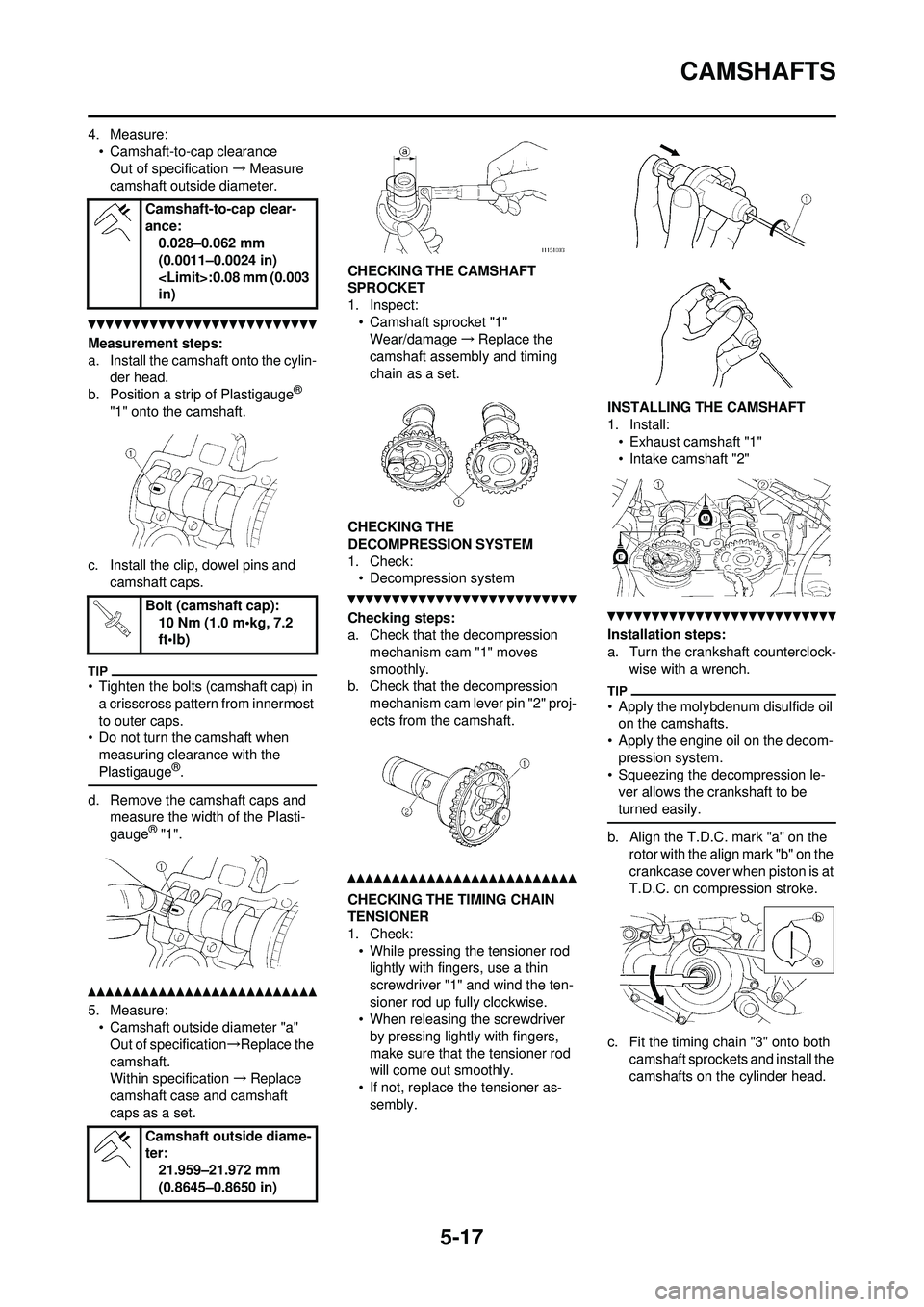
5-17
CAMSHAFTS
4. Measure:• Camshaft-to-cap clearanceOut of specification →Measure
camshaft outside diameter.
Measurement steps:
a. Install the camshaft onto the cylin- der head.
b. Position a strip of Plastigauge
®
"1" onto the camshaft.
c. Install the clip, dowel pins and camshaft caps.
• Tighten the bolts (camshaft cap) in a crisscross pattern from innermost
to outer caps.
• Do not turn the camshaft when
measuring clearance with the
Plastigauge
®.
d. Remove the camshaft caps and measure the width of the Plasti-
gauge
® "1".
5. Measure:• Camshaft outside diameter "a"
Out of specification →Replace the
camshaft.
Within specification →Replace
camshaft case and camshaft
caps as a set. CHECKING THE CAMSHAFT
SPROCKET
1. Inspect:
• Camshaft sprocket "1"Wear/damage →Replace the
camshaft assemb ly and timing
chain as a set.
CHECKING THE
DECOMPRESSION SYSTEM
1. Check: • Decompression system
Checking steps:
a. Check that the decompression
mechanism cam "1" moves
smoothly.
b. Check that the decompression
mechanism cam lever pin "2" proj-
ects from the camshaft.
CHECKING THE TIMING CHAIN
TENSIONER
1. Check:• While pressing the tensioner rod lightly with fingers, use a thin
screwdriver "1" and wind the ten-
sioner rod up fully clockwise.
• When releasing the screwdriver
by pressing lightly with fingers,
make sure that the tensioner rod
will come out smoothly.
• If not, replace the tensioner as- sembly. INSTALLING THE CAMSHAFT
1. Install:
• Exhaust camshaft "1"
• Intake camshaft "2"
Installation steps:
a. Turn the crankshaft counterclock- wise with a wrench.
• Apply the molybdenum disulfide oil on the camshafts.
• Apply the engine oil on the decom- pression system.
• Squeezing the decompression le-
ver allows the crankshaft to be
turned easily.
b. Align the T.D.C. mark "a" on the rotor with the align mark "b" on the
crankcase cover when piston is at
T.D.C. on compression stroke.
c. Fit the timing chain "3" onto both camshaft sprockets and install the
camshafts on the cylinder head.
Camshaft-to-cap clear-
ance:
0.028–0.062 mm
(0.0011–0.0024 in)
in)
Bolt (camshaft cap): 10 Nm (1.0 m•kg, 7.2
ft•lb)
Camshaft outside diame-
ter: 21.959–21.972 mm
(0.8645–0.8650 in)