weight YAMAHA WR 250F 2010 Owners Manual
[x] Cancel search | Manufacturer: YAMAHA, Model Year: 2010, Model line: WR 250F, Model: YAMAHA WR 250F 2010Pages: 232, PDF Size: 13.94 MB
Page 7 of 232
• PROPERLY SECURE THE MA-CHINE BEFORE TRANSPORTING
IT.
When transporting the machine in
another vehicle, always be sure it is
properly secured and in an upright
position and that the fuel cock is in
the "OFF" position. Otherwise, fuel
may leak out of the carburetor or
fuel tank.
F.I.M. MACHINE WEIGHTS
(Except for Canada)
Weights of machines without fuel
The minimum weights for motocross
machines are:
for the class 125 cc:
minimum 88 kg (194 lb)
for the class 250 cc:
minimum 98 kg (216 lb)
for the class 500 cc:
minimum 102 kg (225 lb)
In modifying your machine (e.g., for
weight reduction), take note of the
above limits of weight.
HOW TO USE THIS MANUAL
FINDING THE REQUIRED PAGE
1. This manual consists of seven chapters; "General Information",
"Specifications", "Regular inspec-
tion and adjustments", "Tuning",
"Engine", "Chassis" and "Electri-
cal".
2. The table of contents is at the be-
ginning of the manual. Look over
the general layout of the book be-
fore finding then required chapter
and item.
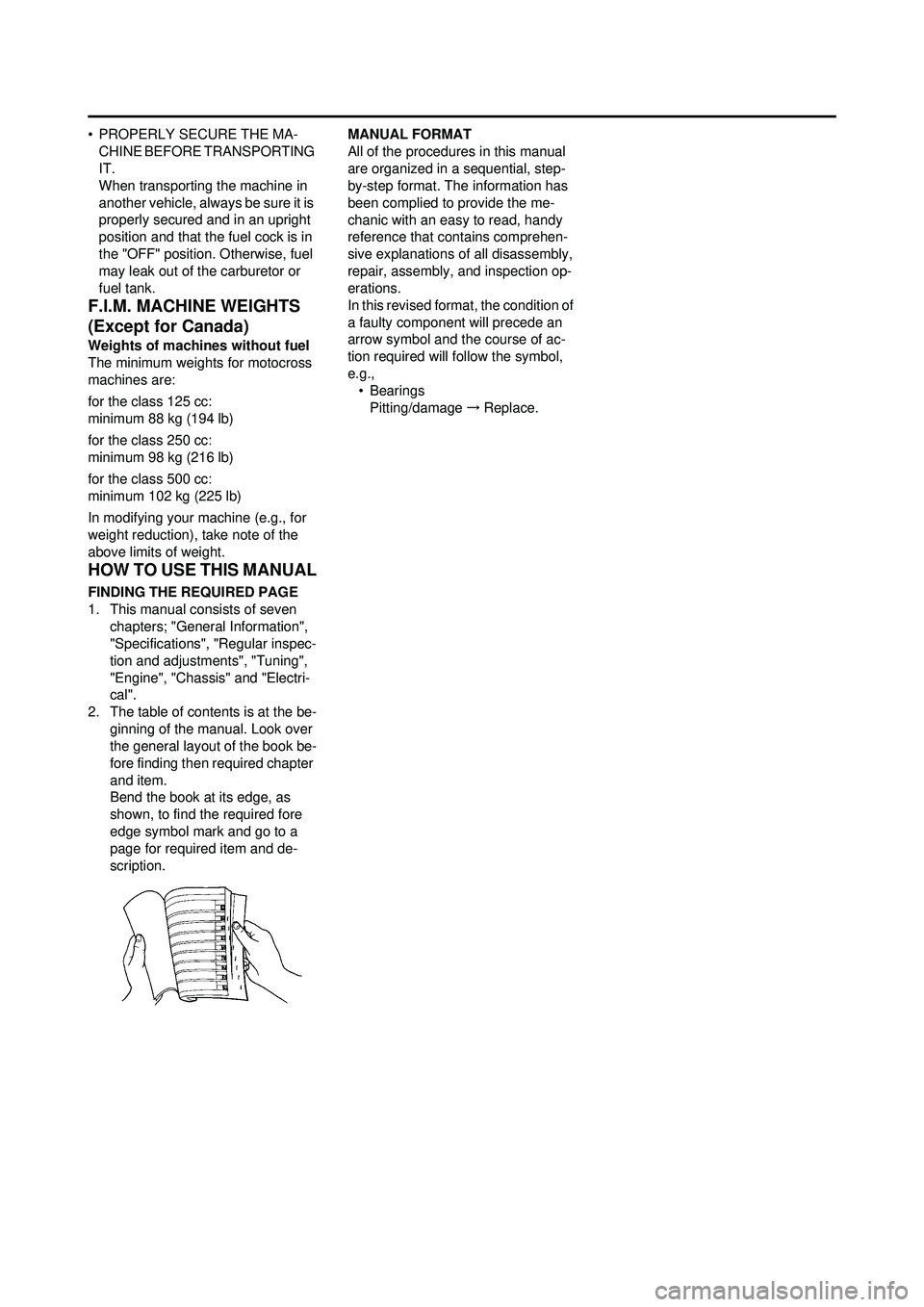
Bend the book at its edge, as
shown, to find the required fore
edge symbol mark and go to a
page for required item and de-
scription. MANUAL FORMAT
All of the procedures in this manual
are organized in a sequential, step-
by-step format. The information has
been complied to provide the me-
chanic with an easy to read, handy
reference that contains comprehen-
sive explanations of all disassembly,
repair, assembly, and inspection op-
erations.
In this revised format, the condition of
a faulty component will precede an
arrow symbol and the course of ac-
tion required will follow the symbol,
e.g.,
•Bearings
Pitting/damage →Replace.
Page 8 of 232
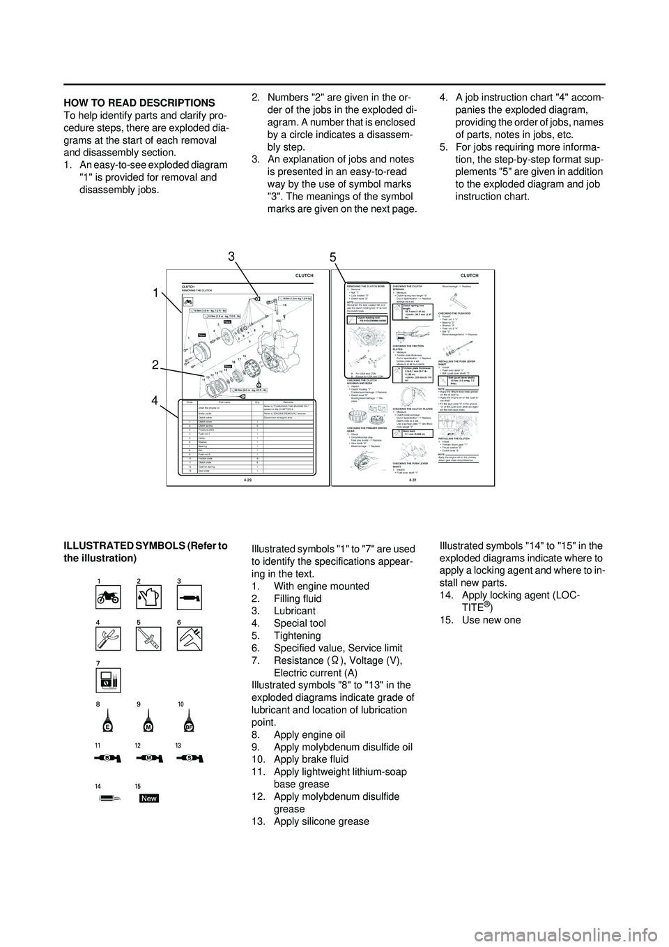
HOW TO READ DESCRIPTIONS
To help identify parts and clarify pro-
cedure steps, there are exploded dia-
grams at the start of each removal
and disassembly section.
1. An easy-to-see exploded diagram "1" is provided for removal and
disassembly jobs. 2. Numbers "2" are given in the or-
der of the jobs in the exploded di-
agram. A number that is enclosed
by a circle indicates a disassem-
bly step.
3. An explanation of jobs and notes is presented in an easy-to-read
way by the use of symbol marks
"3". The meanings of the symbol
marks are given on the next page. 4. A job instruction chart "4" accom-
panies the exploded diagram,
providing the order of jobs, names
of parts, notes in jobs, etc.
5. For jobs requiring more informa- tion, the step-by-step format sup-
plements "5" are given in addition
to the exploded diagram and job
instruction chart.
ILLUSTRATED SYMBO LS (Refer to
the illustration) Illustrated symbols "1" to "7" are used
to identify the specifications appear-
ing in the text.
1. With engine mounted
2. Filling fluid
3. Lubricant
4. Special tool
5. Tightening
6. Specified value, Service limit
7. Resistance (
Ω), Voltage (V),
Electric current (A)
Illustrated symbols "8" to "13" in the
exploded diagrams indicate grade of
lubricant and location of lubrication
point.
8. Apply engine oil
9. Apply molybdenum disulfide oil
10. Apply brake fluid
11. Apply lightweight lithium-soap base grease
12. Apply molybdenum disulfide
grease
13. Apply silicone grease Illustrated symbols "14" to "15" in the
exploded diagrams indicate where to
apply a locking agent and where to in-
stall new parts.
14. Apply locking agent (LOC-
TITE
®)
15. Use new one
1
2 3
4 5
Page 17 of 232
1-7
CHECKING OF CONNECTION
3. When disassembling the ma-chine, keep mated parts together.
They include gears, cylinders,
pistons, and other mated parts
that have been "mated" through
normal wear. Mated parts must
be reused as an assembly or re-
placed.
4. During the machine disassembly, clean all parts and place them in
trays in the order of disassembly.
This will speed up assembly time
and help assure that all parts are
correctly reinstalled.
5. Keep away from fire.
ALL REPLACEMENT PARTS
1. We recommend to use Yamaha genuine parts for all replace-
ments. Use oil and/or grease rec-
ommended by Yamaha for
assembly and adjustment.
GASKETS, OIL SEALS AND O-
RINGS
1. All gaskets, oil seals, and O-rings should be replaced when an en-
gine is overhauled. All gasket sur-
faces, oil seal lips, and O-rings
must be cleaned.
2. Properly oil all mating parts and bearings during reassembly. Ap-
ply grease to the oil seal lips.
LOCK WASHERS/PLATES AND
COTTER PINS
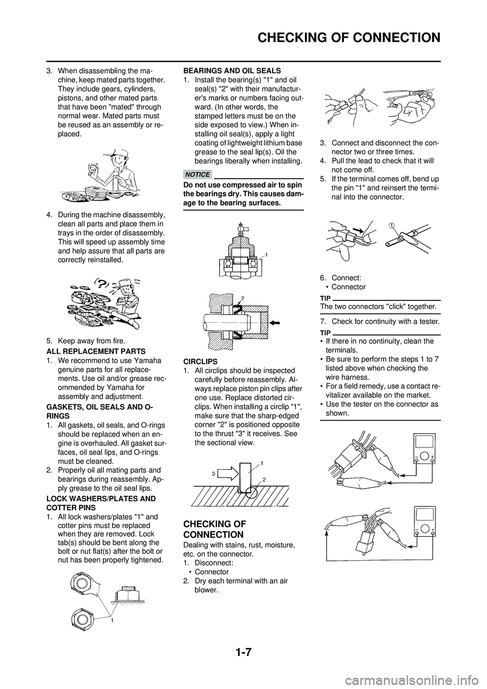
1. All lock washers/plates "1" and cotter pins must be replaced
when they are removed. Lock
tab(s) should be bent along the
bolt or nut flat(s) after the bolt or
nut has been properly tightened. BEARINGS AND OIL SEALS
1. Install the bearing(s) "1" and oil
seal(s) "2" with their manufactur-
er's marks or numbers facing out-
ward. (In other words, the
stamped letters must be on the
side exposed to view.) When in-
stalling oil seal(s), apply a light
coating of lightweight lithium base
grease to the seal lip(s). Oil the
bearings liberally when installing.
Do not use compressed air to spin
the bearings dry. This causes dam-
age to the bearing surfaces.
CIRCLIPS
1. All circlips should be inspected carefully before reassembly. Al-
ways replace piston pin clips after
one use. Replace distorted cir-
clips. When installing a circlip "1",
make sure that the sharp-edged
corner "2" is positioned opposite
to the thrust "3" it receives. See
the sectional view.
CHECKING OF
CONNECTION
Dealing with stains, rust, moisture,
etc. on the connector.
1. Disconnect:• Connector
2. Dry each terminal with an air blower. 3. Connect and disconnect the con-
nector two or three times.
4. Pull the lead to check that it will not come off.
5. If the terminal comes off, bend up
the pin "1" and reinsert the termi-
nal into the connector.
6. Connect: • Connector
The two connectors "click" together.
7. Check for continuity with a tester.
• If there in no continuity, clean the terminals.
• Be sure to perform the steps 1 to 7 listed above when checking the
wire harness.
• For a field remedy, use a contact re- vitalizer available on the market.
• Use the tester on the connector as shown.
Page 32 of 232
2-1
GENERAL SPECIFICATIONS
SPECIFICATIONS
GENERAL SPECIFICATIONS
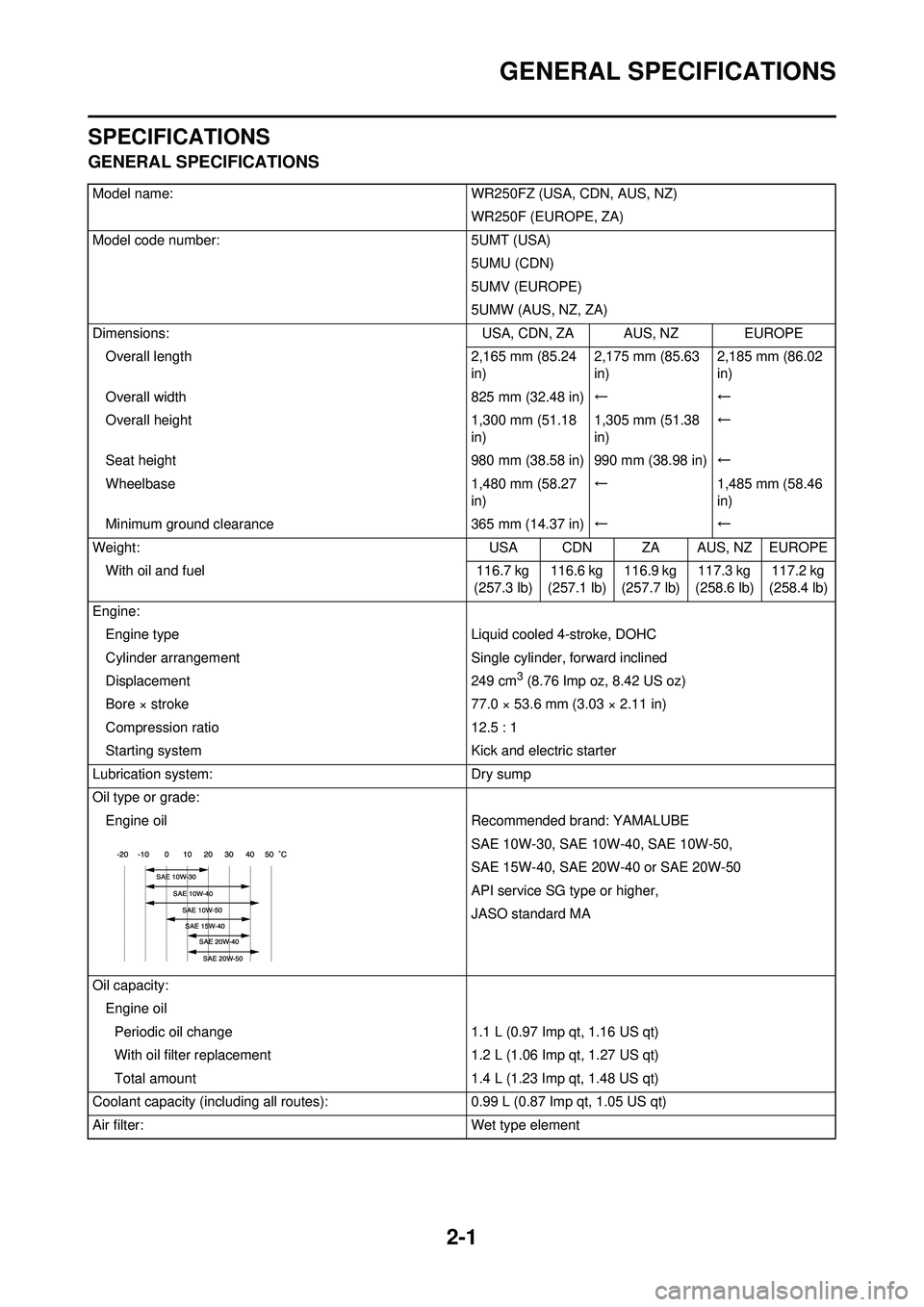
Model name:WR250FZ (USA, CDN, AUS, NZ)
WR250F (EUROPE, ZA)
Model code number: 5UMT (USA)
5UMU (CDN)
5UMV (EUROPE)
5UMW (AUS, NZ, ZA)
Dimensions: USA, CDN, ZA AUS, NZ EUROPE
Overall length 2,165 mm (85.24
in) 2,175 mm (85.63
in)2,185 mm (86.02
in)
Overall width 825 mm (32.48 in)←←
Overall height 1,300 mm (51.18
in) 1,305 mm (51.38
in)←
Seat height 980 mm (38.58 in) 990 mm (38.98 in)←
Wheelbase 1,480 mm (58.27
in) ←
1,485 mm (58.46
in)
Minimum ground clearance 365 mm (14.37 in)←←
Weight: USA CDN ZA AUS, NZ EUROPE
With oil and fuel 116.7 kg
(257.3 lb) 116.6 kg
(257.1 lb) 116.9 kg
(257.7 lb) 117.3 kg
(258.6 lb) 117.2 kg
(258.4 lb)
Engine: Engine type Liquid cooled 4-stroke, DOHC
Cylinder arrangement Single cylinder, forward inclined
Displacement 249 cm
3 (8.76 Imp oz, 8.42 US oz)
Bore × stroke 77.0 × 53.6 mm (3.03 × 2.11 in)
Compression ratio 12.5 : 1
Starting system Kick and electric starter
Lubrication system: Dry sump
Oil type or grade: Engine oil Recommended brand: YAMALUBE
SAE 10W-30, SAE 10W-40, SAE 10W-50,
SAE 15W-40, SAE 20W-40 or SAE 20W-50
API service SG type or higher,
JASO standard MA
Oil capacity: Engine oilPeriodic oil change 1.1 L (0.97 Imp qt, 1.16 US qt)
With oil filter replacement 1.2 L (1.06 Imp qt, 1.27 US qt)
Total amount 1.4 L (1.23 Imp qt, 1.48 US qt)
Coolant capacity (including all routes ):0.99 L (0.87 Imp qt, 1.05 US qt)
Air filter: Wet type element
Page 43 of 232
2-12
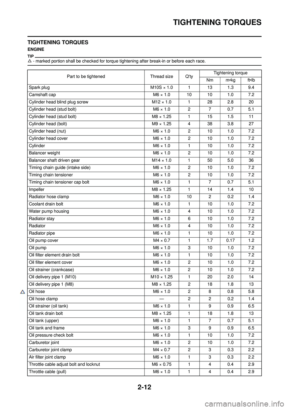
TIGHTENING TORQUES
TIGHTENING TORQUES
ENGINE
△- marked portion shall be checked for torque ti ghtening after break-in or before each race.
Part to be tightenedThread size Q'tyTightening torque
Nm m•kg ft•lb
Spark plug M10S × 1.0 1 13 1.3 9.4
Camshaft cap M6 × 1.0 10 10 1.0 7.2
Cylinder head blind plug screw M12 × 1.0 1 28 2.8 20
Cylinder head (stud bolt) M6 × 1.0 2 7 0.7 5.1
Cylinder head (stud bolt) M8 × 1.25 1 15 1.5 11
Cylinder head (bolt) M9 × 1.25 4 38 3.8 27
Cylinder head (nut) M6 × 1.0 2 10 1.0 7.2
Cylinder head cover M6 × 1.0 2 10 1.0 7.2
Cylinder M6 × 1.0 1 10 1.0 7.2
Balancer weight M6 × 1.0 2 10 1.0 7.2
Balancer shaft driven gear M14 × 1.0 1 50 5.0 36
Timing chain guide (intake side) M6 × 1.0 2 10 1.0 7.2
Timing chain tensioner M6 × 1.0 2 10 1.0 7.2
Timing chain tensioner cap bolt M6 × 1.0 1 7 0.7 5.1
Impeller M8 × 1.25 1 14 1.4 10
Radiator hose clamp M6 × 1.0 10 2 0.2 1.4
Coolant drain bolt M6 × 1.0 1 10 1.0 7.2
Water pump housing M6 × 1.0 4 10 1.0 7.2
Radiator stay M6 × 1.0 6 10 1.0 7.2
Radiator M6 × 1.0 4 10 1.0 7.2
Radiator pipe M6 × 1.0 1 10 1.0 7.2
Oil pump cover M4 × 0.7 1 1.7 0.17 1.2
Oil pump M6 × 1.0 3 10 1.0 7.2
Oil filter element drain bolt M6 × 1.0 1 10 1.0 7.2
Oil filter element cover M6 × 1.0 2 10 1.0 7.2
Oil strainer (crankcase) M6 × 1.0 2 10 1.0 7.2
Oil delivery pipe 1 (M10) M10 × 1.25 1 20 2.0 14
Oil delivery pipe 1 (M8) M8 × 1.25 2 18 1.8 13
Oil hose M6 × 1.0 2 8 0.8 5.8
△ Oil hose clamp —2 2 0.2 1.4
Oil strainer (oil tank) M6 × 1.0 1 9 0.9 6.5
Oil tank drain bolt M8 × 1.25 1 18 1.8 13
Oil tank (upper) M6 × 1.0 1 7 0.7 5.1
Oil tank and frame M6 × 1.0 3 9 0.9 6.5
Oil pressure check bolt M6 × 1.0 1 10 1.0 7.2
Carburetor joint M6 × 1.0 2 10 1.0 7.2
Carburetor joint clamp M4 × 0.7 2 3 0.3 2.2
Air filter joint clamp M6 × 1.0 1 3 0.3 2.2
Throttle cable adjust bolt and locknut M6 × 0.75 1 4 0.4 2.9
Throttle cable (pull) M6 × 1.0 1 4 0.4 2.9
Page 48 of 232
2-17
TIGHTENING TORQUES
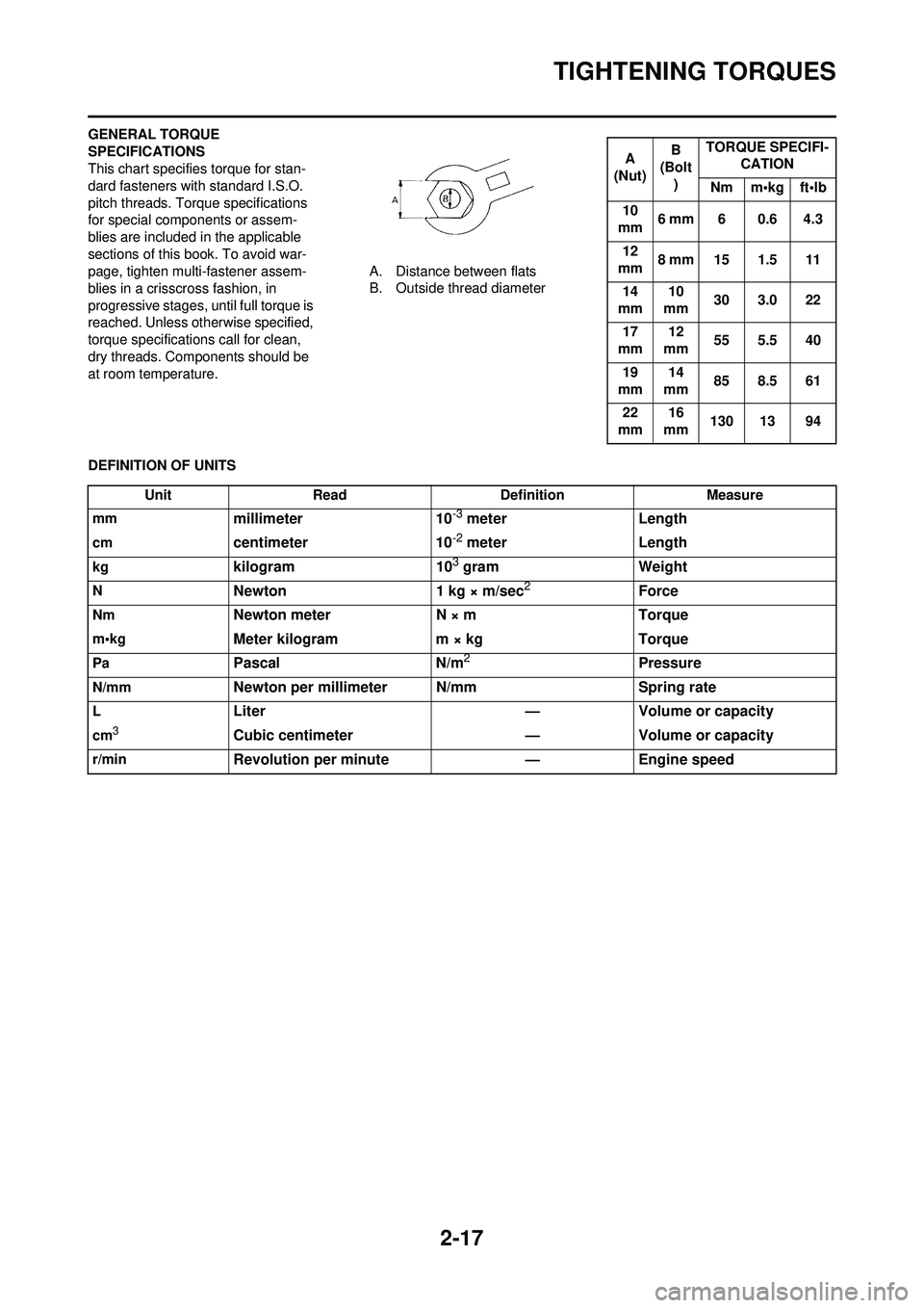
GENERAL TORQUE
SPECIFICATIONS
This chart specifies torque for stan-
dard fasteners with standard I.S.O.
pitch threads. Torque specifications
for special components or assem-
blies are included in the applicable
sections of this book. To avoid war-
page, tighten multi-fastener assem-
blies in a crisscross fashion, in
progressive stages, until full torque is
reached. Unless otherwise specified,
torque specifications call for clean,
dry threads. Components should be
at room temperature.A. Distance between flats
B. Outside thread diameter
DEFINITION OF UNITS
A
(Nut) B
(Bolt
) TORQUE SPECIFI-
CATION
Nm m•kg ft•lb
10
mm 6 mm 6 0.6 4.3
12
mm 8 mm 15 1.5 11
14
mm 10
mm 30 3.0 22
17
mm 12
mm 55 5.5 40
19
mm 14
mm 85 8.5 61
22
mm 16
mm 130 13 94
Unit
Read Definition Measure
mm
millimeter 10-3 meterLength
cmcentimeter 10-2 meterLength
kgkilogram 103 gramWeight
NNewton 1 kg × m/sec2Force
NmNewton meter N × mTorque
m•kgMeter kilogram m × kg Torque
PaPascalN/m2Pressure
N/mmNewton per millimeter N/mm Spring rate
LLiter—Volume or capacity
cm3Cubic centimeter —Volume or capacity
r/minRevolution per minute —Engine speed
Page 87 of 232
3-28
CHASSIS
LUBRICATION
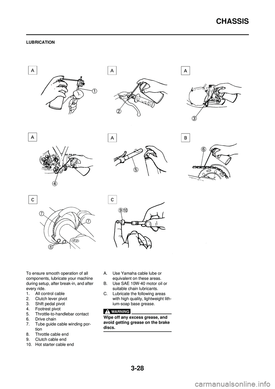
To ensure smooth operation of all
components, lubricate your machine
during setup, after break-in, and after
every ride.
1. All control cable
2. Clutch lever pivot
3. Shift pedal pivot
4. Footrest pivot
5. Throttle-to-handlebar contact
6. Drive chain
7. Tube guide cable winding por-tion
8. Throttle cable end
9. Clutch cable end
10. Hot starter cable end A. Use Yamaha cable lube or
equivalent on these areas.
B. Use SAE 10W-40 motor oil or
suitable chain lubricants.
C. Lubricate the following areas with high quality, lightweight lith-
ium-soap base grease.
Wipe off any excess grease, and
avoid getting grease on the brake
discs.
Page 110 of 232
5-7
CARBURETOR
HANDLING NOTE
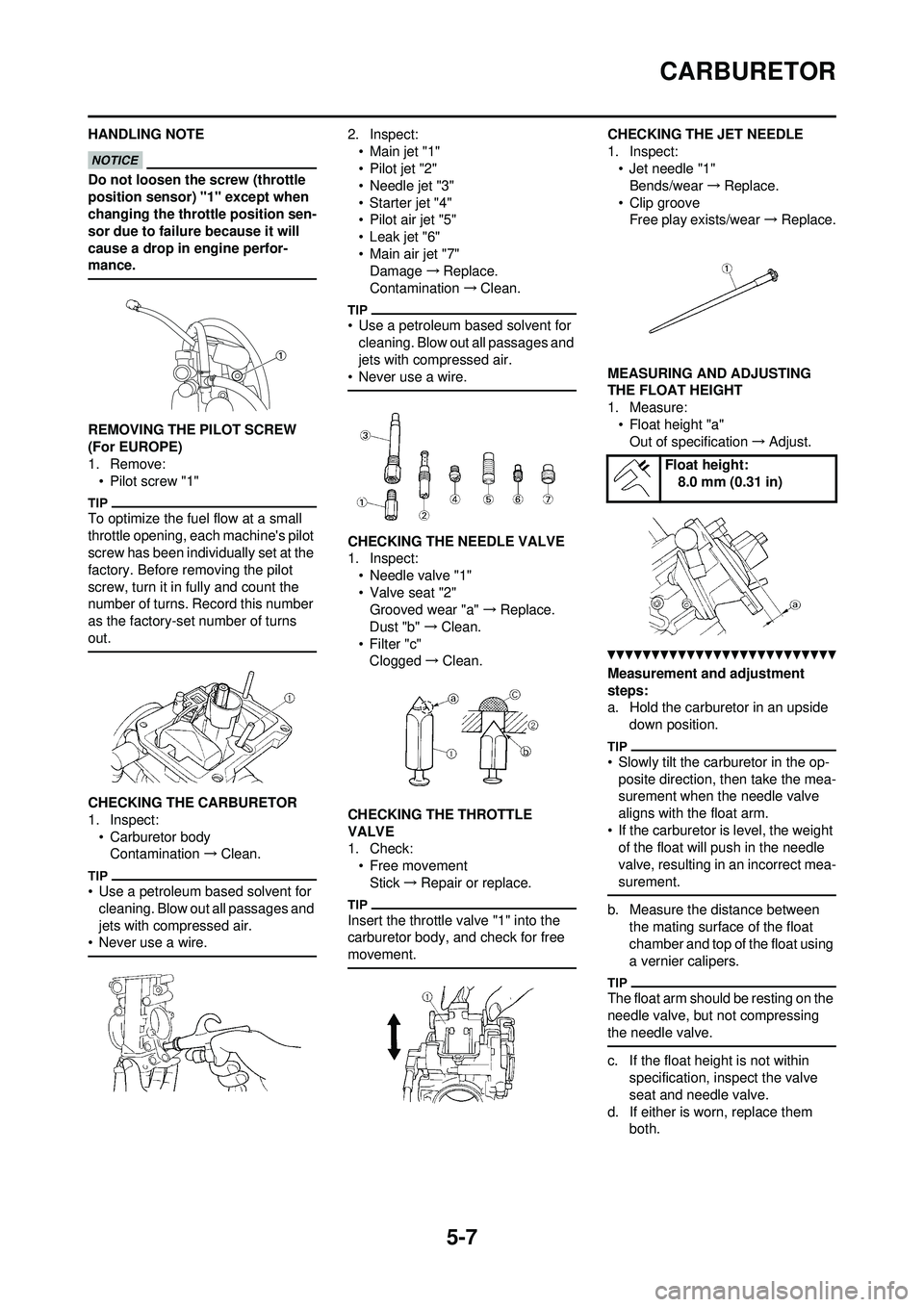
Do not loosen the screw (throttle
position sensor) "1" except when
changing the throttle position sen-
sor due to failure because it will
cause a drop in engine perfor-
mance.
REMOVING THE PILOT SCREW
(For EUROPE)
1. Remove: • Pilot screw "1"
To optimize the fuel flow at a small
throttle opening, each machine's pilot
screw has been individually set at the
factory. Before removing the pilot
screw, turn it in fully and count the
number of turns. Record this number
as the factory-set number of turns
out.
CHECKING THE CARBURETOR
1. Inspect:• Carburetor bodyContamination →Clean.
• Use a petroleum based solvent for
cleaning. Blow out all passages and
jets with compressed air.
• Never use a wire.
2. Inspect:
•Main jet "1"
• Pilot jet "2"
• Needle jet "3"
• Starter jet "4"
•Pilot air jet "5"
• Leak jet "6"
• Main air jet "7"Damage →Replace.
Contamination →Clean.
• Use a petroleum based solvent for
cleaning. Blow out all passages and
jets with compressed air.
• Never use a wire.
CHECKING THE NEEDLE VALVE
1. Inspect: • Needle valve "1"
• Valve seat "2"Grooved wear "a" →Replace.
Dust "b" →Clean.
• Filter "c" Clogged →Clean.
CHECKING THE THROTTLE
VALVE
1. Check: • Free movement
Stick →Repair or replace.
Insert the throttle valve "1" into the
carburetor body, and check for free
movement.
CHECKING THE JET NEEDLE
1. Inspect: • Jet needle "1"Bends/wear →Replace.
• Clip groove Free play exists/wear →Replace.
MEASURING AND ADJUSTING
THE FLOAT HEIGHT
1. Measure: • Float height "a"Out of specification →Adjust.
Measurement and adjustment
steps:
a. Hold the carburetor in an upside
down position.
• Slowly tilt the ca rburetor in the op-
posite direction, then take the mea-
surement when the needle valve
aligns with the float arm.
• If the carburetor is level, the weight of the float will push in the needle
valve, resulting in an incorrect mea-
surement.
b. Measure the distance between the mating surface of the float
chamber and top of the float using
a vernier calipers.
The float arm should be resting on the
needle valve, but not compressing
the needle valve.
c. If the float height is not within specification, inspect the valve
seat and needle valve.
d. If either is worn, replace them both.
Float height:
8.0 mm (0.31 in)
Page 143 of 232
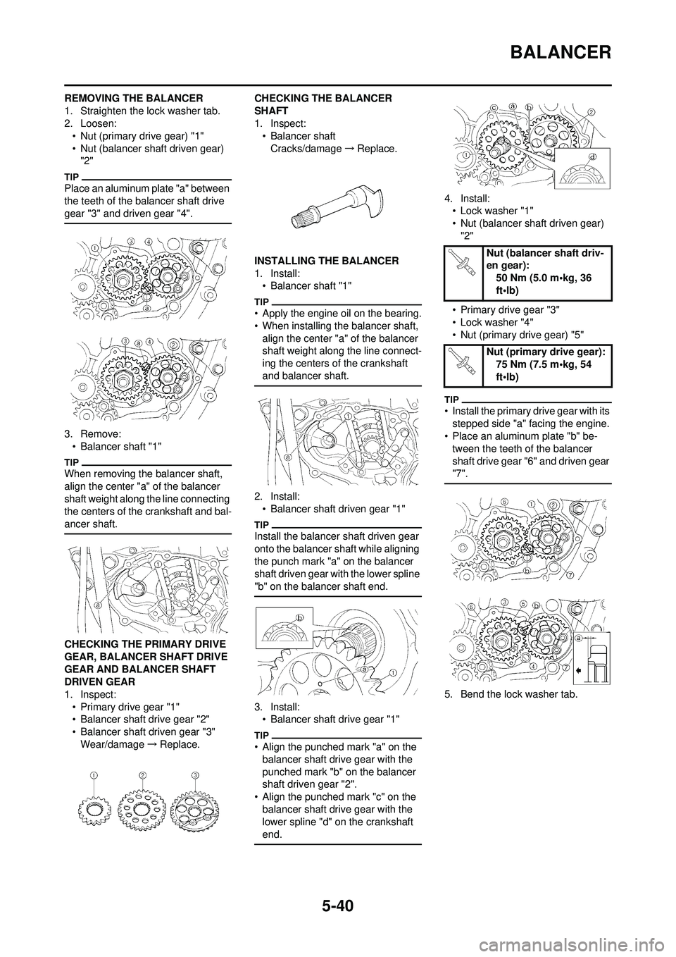
5-40
BALANCER
REMOVING THE BALANCER
1. Straighten the lock washer tab.
2. Loosen:• Nut (primary drive gear) "1"
• Nut (balancer shaft driven gear) "2"
Place an aluminum plate "a" between
the teeth of the balancer shaft drive
gear "3" and driven gear "4".
3. Remove:• Balancer shaft "1"
When removing the balancer shaft,
align the center "a" of the balancer
shaft weight along the line connecting
the centers of the crankshaft and bal-
ancer shaft.
CHECKING THE PRIMARY DRIVE
GEAR, BALANCER SHAFT DRIVE
GEAR AND BALANCER SHAFT
DRIVEN GEAR
1. Inspect:
• Primary drive gear "1"
• Balancer shaft drive gear "2"
• Balancer shaft driven gear "3"Wear/damage →Replace. CHECKING THE BALANCER
SHAFT
1. Inspect:
• Balancer shaft
Cracks/damage →Replace.
INSTALLING THE BALANCER
1. Install: • Balancer shaft "1"
• Apply the engine oil on the bearing.
• When installing the balancer shaft, align the center "a" of the balancer
shaft weight along the line connect-
ing the centers of the crankshaft
and balancer shaft.
2. Install:• Balancer shaft driven gear "1"
Install the balancer shaft driven gear
onto the balancer shaft while aligning
the punch mark "a" on the balancer
shaft driven gear with the lower spline
"b" on the balancer shaft end.
3. Install:• Balancer shaft drive gear "1"
• Align the punched mark "a" on the balancer shaft drive gear with the
punched mark "b" on the balancer
shaft driven gear "2".
• Align the punched mark "c" on the
balancer shaft drive gear with the
lower spline "d" on the crankshaft
end.
4. Install:• Lock washer "1"
• Nut (balancer shaft driven gear) "2"
• Primary drive gear "3"
• Lock washer "4"
• Nut (primary drive gear) "5"
• Install the primary drive gear with its stepped side "a" facing the engine.
• Place an aluminum plate "b" be-
tween the teeth of the balancer
shaft drive gear "6" and driven gear
"7".
5. Bend the lock washer tab.
Nut (balancer shaft driv-
en gear): 50 Nm (5.0 m•kg, 36
ft•lb)
Nut (primary drive gear): 75 Nm (7.5 m•kg, 54
ft•lb)