light YAMAHA WR 250F 2011 Service Manual
[x] Cancel search | Manufacturer: YAMAHA, Model Year: 2011, Model line: WR 250F, Model: YAMAHA WR 250F 2011Pages: 232, PDF Size: 14.29 MB
Page 185 of 232
6-16
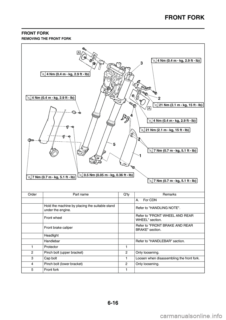
FRONT FORK
FRONT FORK
REMOVING THE FRONT FORK
Order Part name Q'ty Remarks
A. For CDN
Hold the machine by placing the suitable stand
under the engine.Refer to "HANDLING NOTE".
Front wheel Refer to "FRONT WHEEL AND REAR
WHEEL" section.
Front brake caliper Refer to "FRONT BRAKE AND REAR
BRAKE" section.
Headlight
Handlebar Refer to "HANDLEBAR" section.
1 Protector 1
2 Pinch bolt (upper bracket) 2 Only loosening.
3 Cap bolt 1 Loosen when disassembling the front fork.
4 Pinch bolt (lower bracket) 2 Only loosening.
5 Front fork 1
Page 192 of 232
6-23
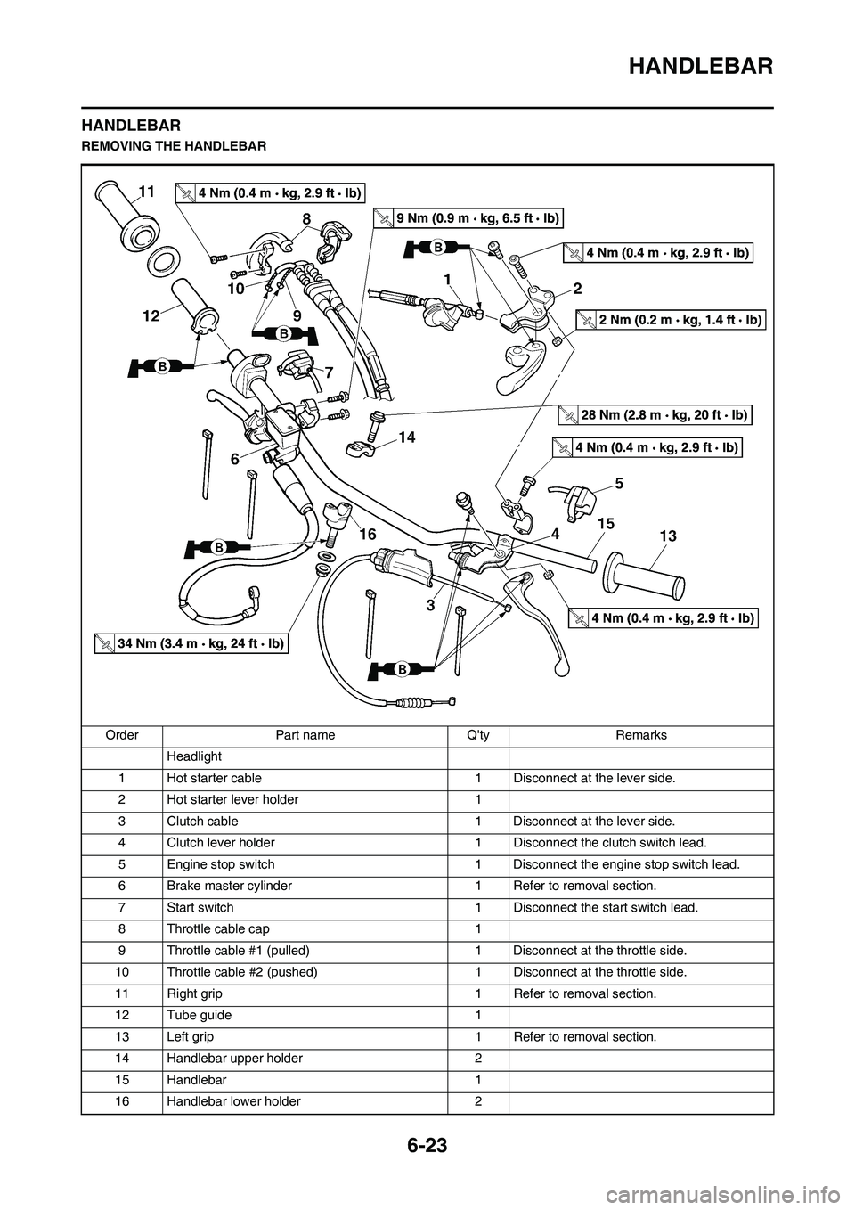
HANDLEBAR
HANDLEBAR
REMOVING THE HANDLEBAR
Order Part name Q'ty Remarks
Headlight
1 Hot starter cable 1 Disconnect at the lever side.
2 Hot starter lever holder 1
3 Clutch cable 1 Disconnect at the lever side.
4 Clutch lever holder 1 Disconnect the clutch switch lead.
5 Engine stop switch 1 Disconnect the engine stop switch lead.
6 Brake master cylinder 1 Refer to removal section.
7 Start switch 1 Disconnect the start switch lead.
8 Throttle cable cap 1
9 Throttle cable #1 (pulled) 1 Disconnect at the throttle side.
10 Throttle cable #2 (pushed) 1 Disconnect at the throttle side.
11 Right grip 1 Refer to removal section.
12 Tube guide 1
13 Left grip 1 Refer to removal section.
14 Handlebar upper holder 2
15 Handlebar 1
16 Handlebar lower holder 2
Page 196 of 232
6-27
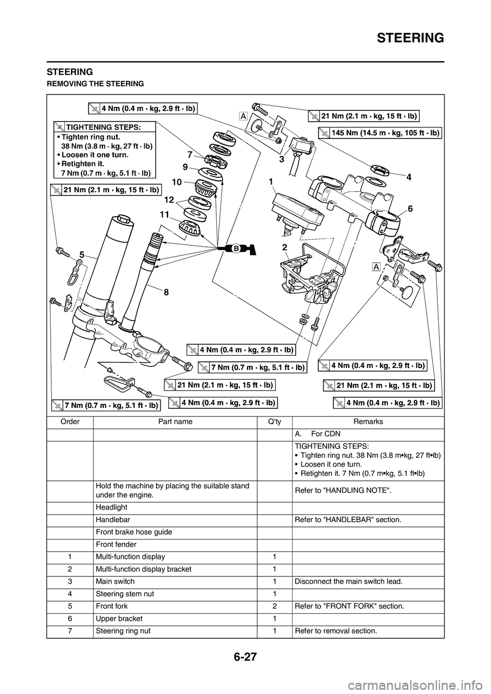
STEERING
STEERING
REMOVING THE STEERING
Order Part name Q'ty Remarks
A. For CDN
TIGHTENING STEPS:
• Tighten ring nut. 38 Nm (3.8 m•kg, 27 ft•lb)
• Loosen it one turn.
• Retighten it. 7 Nm (0.7 m•kg, 5.1 ft•lb)
Hold the machine by placing the suitable stand
under the engine.Refer to "HANDLING NOTE".
Headlight
Handlebar Refer to "HANDLEBAR" section.
Front brake hose guide
Front fender
1 Multi-function display 1
2 Multi-function display bracket 1
3 Main switch 1 Disconnect the main switch lead.
4 Steering stem nut 1
5 Front fork 2 Refer to "FRONT FORK" section.
6 Upper bracket 1
7 Steering ring nut 1 Refer to removal section.
Page 206 of 232
6-37
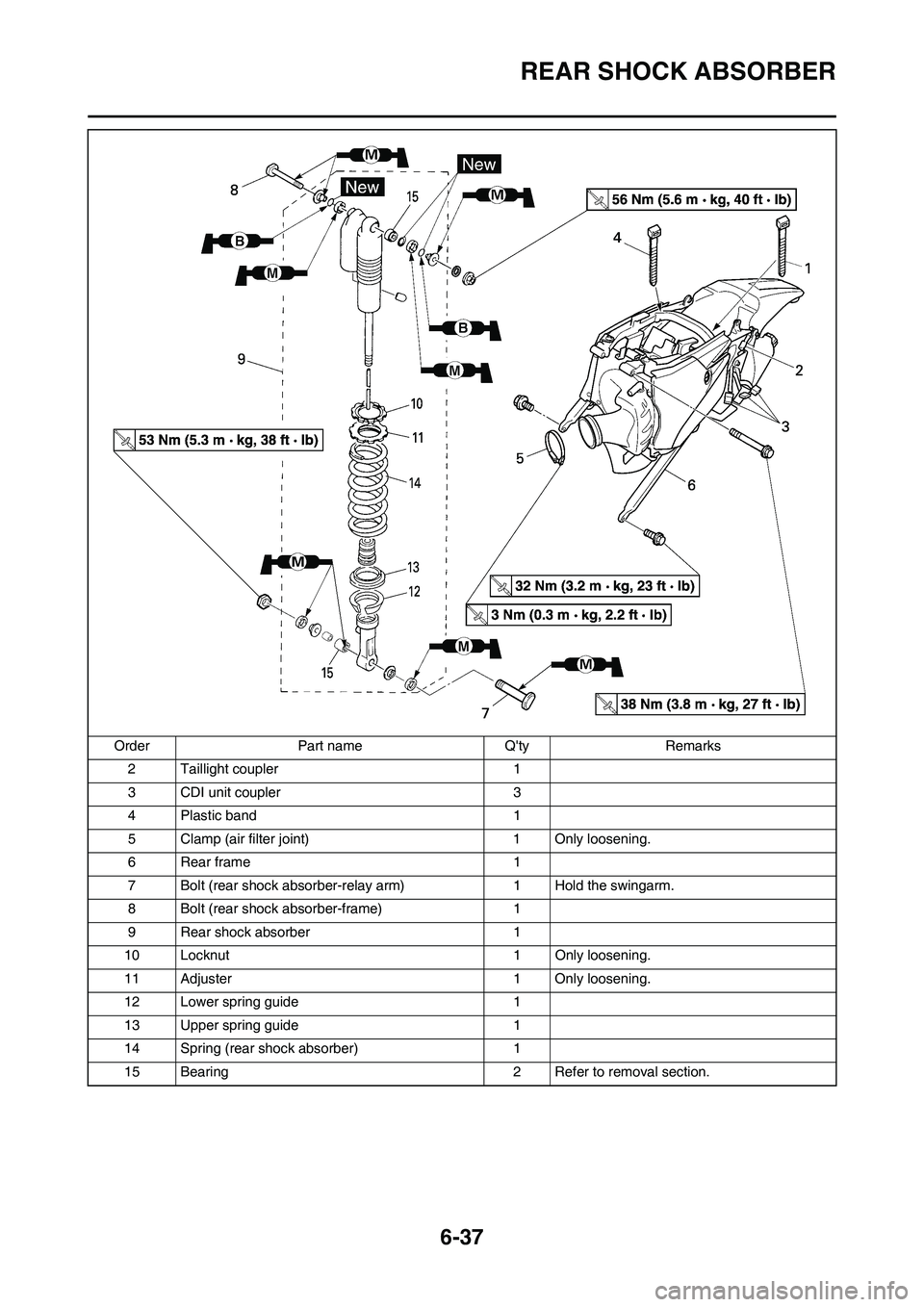
REAR SHOCK ABSORBER
2 Taillight coupler 1
3 CDI unit coupler 3
4 Plastic band 1
5 Clamp (air filter joint) 1 Only loosening.
6Rear frame 1
7 Bolt (rear shock absorber-relay arm) 1 Hold the swingarm.
8 Bolt (rear shock absorber-frame) 1
9 Rear shock absorber 1
10 Locknut 1 Only loosening.
11 Adjuster 1 Only loosening.
12 Lower spring guide 1
13 Upper spring guide 1
14 Spring (rear shock absorber) 1
15 Bearing 2 Refer to removal section. Order Part name Q'ty Remarks
Page 209 of 232
6-40
REAR SHOCK ABSORBER
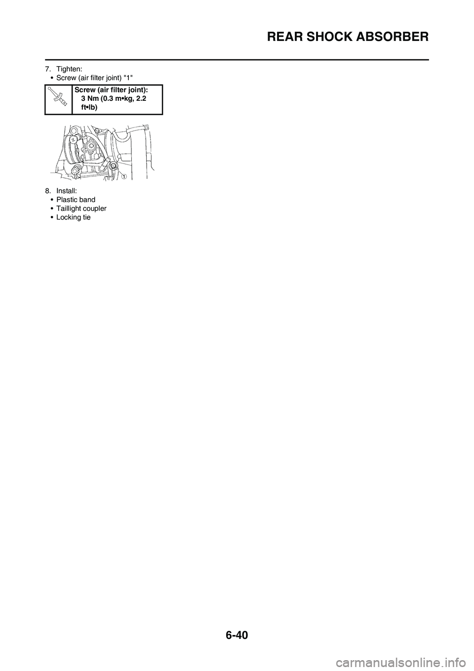
7. Tighten:
• Screw (air filter joint) "1"
8. Install:
• Plastic band
• Taillight coupler
• Locking tieScrew (air filter joint):
3 Nm (0.3 m•kg, 2.2
ft•lb)
Page 210 of 232
7-1
ELECTRICAL COMPONENTS AND WIRING DIAGRAM
ELECTRICAL
This section is intended for those who have basic knowledge and skill concerning the servicing of Yamaha motorcycles
(e.g., Yamaha dealers, service engineers, etc.) Those who have little knowledge and skill concerning servicing are request-
ed not to undertake inspection, adjustment, disassembly, or reassembly only by reference to this manual. It may lead to
servicing trouble and mechanical damage.
ELECTRICAL COMPONENTS AND WIRING DIAGRAM
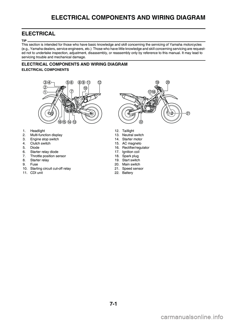
ELECTRICAL COMPONENTS
1. Headlight
2. Multi-function display
3. Engine stop switch
4. Clutch switch
5. Diode
6. Starter relay diode
7. Throttle position sensor
8. Starter relay
9. Fuse
10. Starting circuit cut-off relay
11. CDI unit 12. Taillight
13. Neutral switch
14. Starter motor
15. AC magneto
16. Rectifier/regulator
17. Ignition coil
18. Spark plug
19. Start switch
20. Main switch
21. Speed sensor
22. Battery
Page 211 of 232
7-2
ELECTRICAL COMPONENTS AND WIRING DIAGRAM
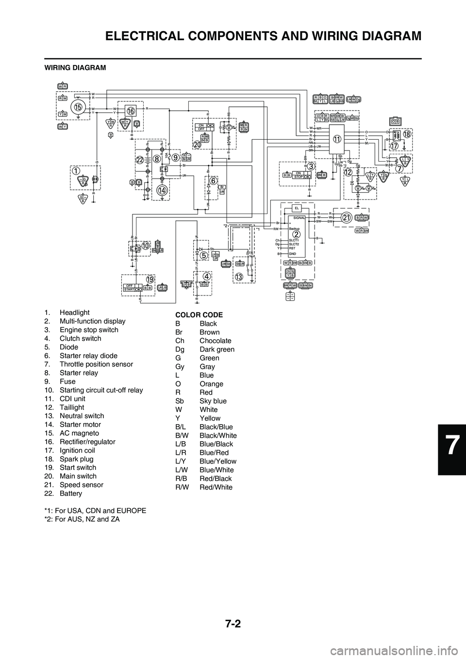
WIRING DIAGRAM
1. Headlight
2. Multi-function display
3. Engine stop switch
4. Clutch switch
5. Diode
6. Starter relay diode
7. Throttle position sensor
8. Starter relay
9. Fuse
10. Starting circuit cut-off relay
11. CDI unit
12. Taillight
13. Neutral switch
14. Starter motor
15. AC magneto
16. Rectifier/regulator
17. Ignition coil
18. Spark plug
19. Start switch
20. Main switch
21. Speed sensor
22. Battery
*1: For USA, CDN and EUROPE
*2: For AUS, NZ and ZACOLOR CODE
BBlack
Br Brown
Ch Chocolate
Dg Dark green
GGreen
Gy Gray
LBlue
O Orange
RRed
Sb Sky blue
WWhite
YYellow
B/L Black/Blue
B/W Black/White
L/B Blue/Black
L/R Blue/Red
L/Y Blue/Yellow
L/W Blue/White
R/B Red/Black
R/W Red/White
7
Page 213 of 232
7-4
IGNITION SYSTEM
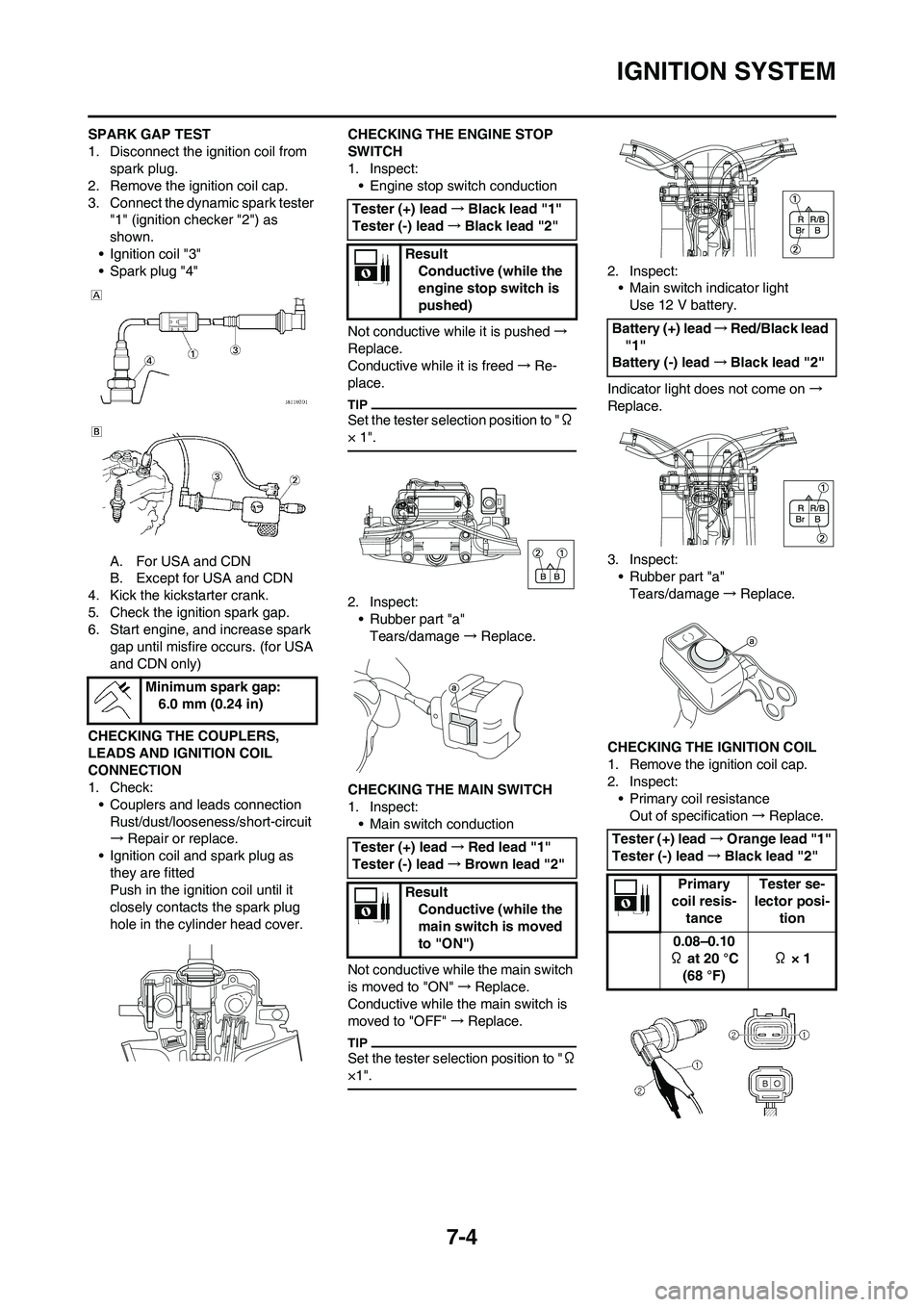
SPARK GAP TEST
1. Disconnect the ignition coil from
spark plug.
2. Remove the ignition coil cap.
3. Connect the dynamic spark tester
"1" (ignition checker "2") as
shown.
• Ignition coil "3"
• Spark plug "4"
A. For USA and CDN
B. Except for USA and CDN
4. Kick the kickstarter crank.
5. Check the ignition spark gap.
6. Start engine, and increase spark
gap until misfire occurs. (for USA
and CDN only)
CHECKING THE COUPLERS,
LEADS AND IGNITION COIL
CONNECTION
1. Check:
• Couplers and leads connection
Rust/dust/looseness/short-circuit
→Repair or replace.
• Ignition coil and spark plug as
they are fitted
Push in the ignition coil until it
closely contacts the spark plug
hole in the cylinder head cover.CHECKING THE ENGINE STOP
SWITCH
1. Inspect:
• Engine stop switch conduction
Not conductive while it is pushed→
Replace.
Conductive while it is freed→Re-
place.
Set the tester selection position to "Ω
× 1".
2. Inspect:
• Rubber part "a"
Tears/damage→ Replace.
CHECKING THE MAIN SWITCH
1. Inspect:
• Main switch conduction
Not conductive while the main switch
is moved to "ON"→Replace.
Conductive while the main switch is
moved to "OFF"→Replace.
Set the tester selection position to "Ω
×1".
2. Inspect:
• Main switch indicator light
Use 12 V battery.
Indicator light does not come on→
Replace.
3. Inspect:
• Rubber part "a"
Tears/damage→Replace.
CHECKING THE IGNITION COIL
1. Remove the ignition coil cap.
2. Inspect:
• Primary coil resistance
Out of specification→Replace. Minimum spark gap:
6.0 mm (0.24 in)
Tester (+) lead→Black lead "1"
Tester (-) lead→Black lead "2"
Result
Conductive (while the
engine stop switch is
pushed)
Tester (+) lead→Red lead "1"
Tester (-) lead→Brown lead "2"
Result
Conductive (while the
main switch is moved
to "ON")
Battery (+) lead→Red/Black lead
"1"
Battery (-) lead→Black lead "2"
Tester (+) lead→Orange lead "1"
Tester (-) lead→Black lead "2"
Primary
coil resis-
tanceTester se-
lector posi-
tion
0.08–0.10
Ω at 20 °C
(68 °F) Ω × 1
Page 227 of 232

7-18
LIGHTING SYSTEM
LIGHTING SYSTEM
INSPECTION STEPS
Refer to the following flow chart when inspecting the lighting system for possible problems.
• Remove the following parts before inspection.
1. Seat
2. Fuel tank
3. Left side cover
• Use the following special tools in this inspection.
Check the bulb and bulb socket. No good→Replace the bulb and/or bulb socket.
OK↓
Check the taillight (LEDs). No good→Replace the taillight assembly.
OK↓
Check the AC magneto. (Lighting coil) No good→Replace.
OK↓
Check the entire lighting system proper for con-
nections.Improperly
connected→Repair or replace.
OK↓
Check the rectifier/regulator. (Out-put voltage) No good→Replace.
Pocket tester:
YU-3112-C/90890-03112
Page 228 of 232
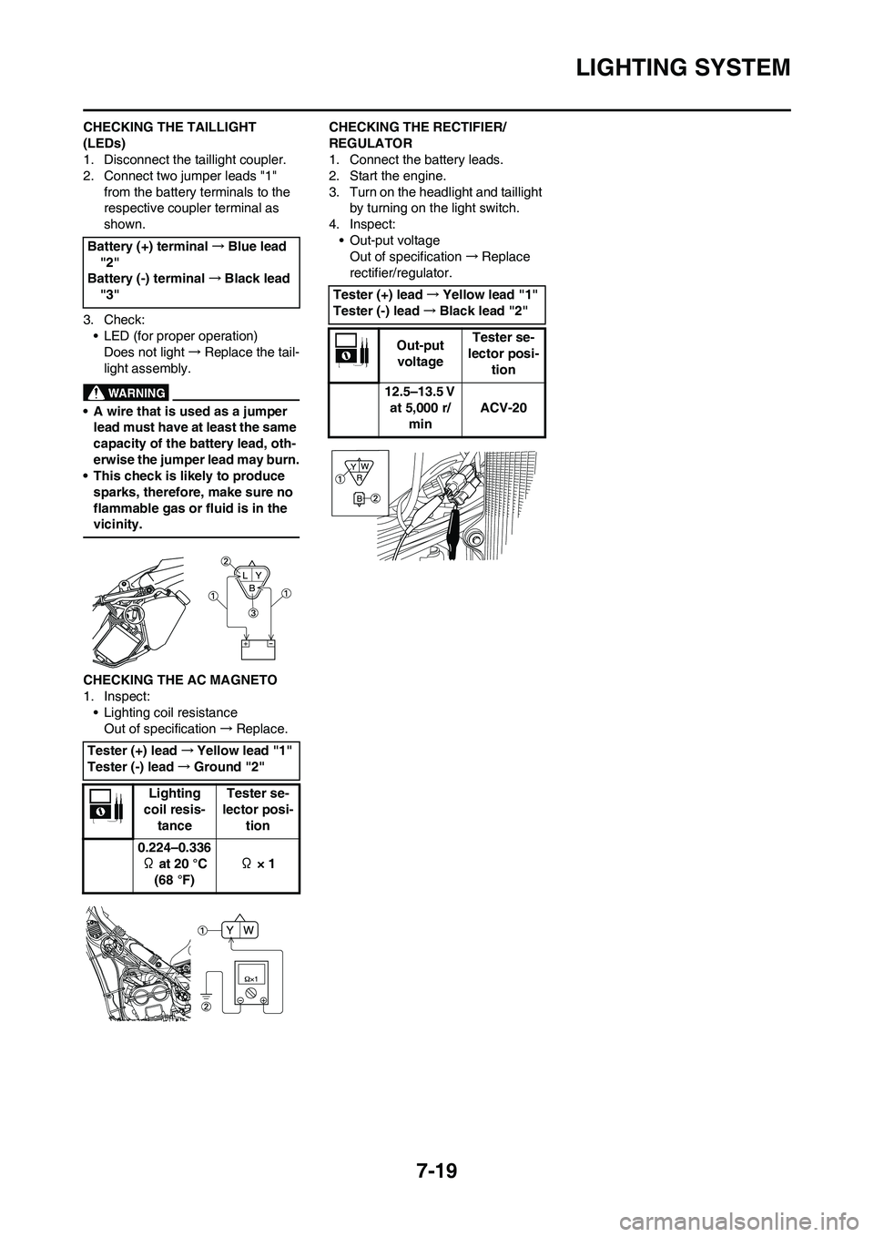
7-19
LIGHTING SYSTEM
CHECKING THE TAILLIGHT
(LEDs)
1. Disconnect the taillight coupler.
2. Connect two jumper leads "1"
from the battery terminals to the
respective coupler terminal as
shown.
3. Check:
• LED (for proper operation)
Does not light→Replace the tail-
light assembly.
• A wire that is used as a jumper
lead must have at least the same
capacity of the battery lead, oth-
erwise the jumper lead may burn.
• This check is likely to produce
sparks, therefore, make sure no
flammable gas or fluid is in the
vicinity.
CHECKING THE AC MAGNETO
1. Inspect:
• Lighting coil resistance
Out of specification→Replace.CHECKING THE RECTIFIER/
REGULATOR
1. Connect the battery leads.
2. Start the engine.
3. Turn on the headlight and taillight
by turning on the light switch.
4. Inspect:
• Out-put voltage
Out of specification→Replace
rectifier/regulator. Battery (+) terminal→Blue lead
"2"
Battery (-) terminal→Black lead
"3"
Tester (+) lead→Yellow lead "1"
Tester (-) lead→Ground "2"
Lighting
coil resis-
tanceTester se-
lector posi-
tion
0.224–0.336
Ω at 20 °C
(68 °F) Ω × 1
Tester (+) lead→Yellow lead "1"
Tester (-) lead→Black lead "2"
Out-put
voltageTester se-
lector posi-
tion
12.5–13.5 V
at 5,000 r/
minACV-20