engine YAMAHA WR 250F 2012 Repair Manual
[x] Cancel search | Manufacturer: YAMAHA, Model Year: 2012, Model line: WR 250F, Model: YAMAHA WR 250F 2012Pages: 232, PDF Size: 13.32 MB
Page 140 of 232
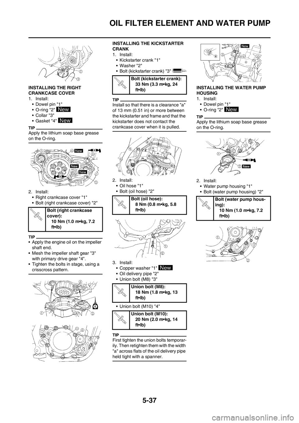
5-37
OIL FILTER ELEMENT AND WATER PUMP
INSTALLING THE RIGHT
CRANKCASE COVER
1. Install:
• Dowel pin "1"
• O-ring "2"
•Collar "3"
• Gasket "4"
Apply the lithium soap base grease
on the O-ring.
2. Install:
• Right crankcase cover "1"
• Bolt (right crankcase cover) "2"
• Apply the engine oil on the impeller
shaft end.
• Mesh the impeller shaft gear "3"
with primary drive gear "4".
• Tighten the bolts in stage, using a
crisscross pattern.
INSTALLING THE KICKSTARTER
CRANK
1. Install:
• Kickstarter crank "1"
• Washer "2"
• Bolt (kickstarter crank) "3"
Install so that there is a clearance "a"
of 13 mm (0.51 in) or more between
the kickstarter and frame and that the
kickstarter does not contact the
crankcase cover when it is pulled.
2. Install:
• Oil hose "1"
• Bolt (oil hose) "2"
3. Install:
• Copper washer "1"
• Oil delivery pipe "2"
• Union bolt (M8) "3"
• Union bolt (M10) "4"
First tighten the union bolts temporar-
ily. Then retighten them with the width
"a" across flats of the oil delivery pipe
held tight with a spanner.
INSTALLING THE WATER PUMP
HOUSING
1. Install:
• Dowel pin "1"
• O-ring "2"
Apply the lithium soap base grease
on the O-ring.
2. Install:
• Water pump housing "1"
• Bolt (water pump housing) "2"
Bolt (right crankcase
cover):
10 Nm (1.0 m•kg, 7.2
ft•lb)
Bolt (kickstarter crank):
33 Nm (3.3 m•kg, 24
ft•lb)
Bolt (oil hose):
8 Nm (0.8 m•kg, 5.8
ft•lb)
Union bolt (M8):
18 Nm (1.8 m•kg, 13
ft•lb)
Union bolt (M10):
20 Nm (2.0 m•kg, 14
ft•lb)
Bolt (water pump hous-
ing):
10 Nm (1.0 m•kg, 7.2
ft•lb)
Page 143 of 232
5-40
BALANCER
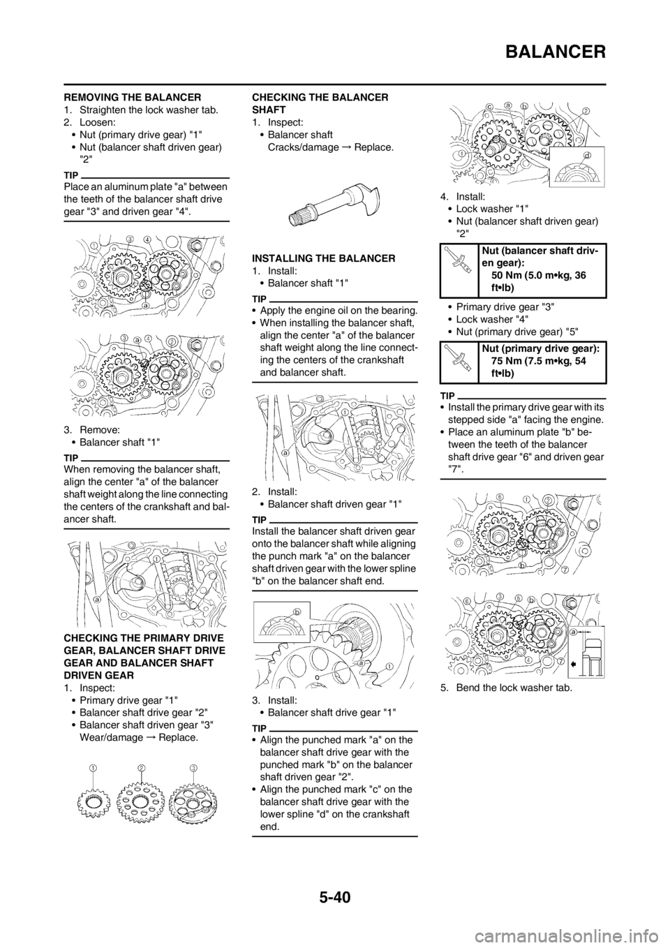
REMOVING THE BALANCER
1. Straighten the lock washer tab.
2. Loosen:
• Nut (primary drive gear) "1"
• Nut (balancer shaft driven gear)
"2"
Place an aluminum plate "a" between
the teeth of the balancer shaft drive
gear "3" and driven gear "4".
3. Remove:
• Balancer shaft "1"
When removing the balancer shaft,
align the center "a" of the balancer
shaft weight along the line connecting
the centers of the crankshaft and bal-
ancer shaft.
CHECKING THE PRIMARY DRIVE
GEAR, BALANCER SHAFT DRIVE
GEAR AND BALANCER SHAFT
DRIVEN GEAR
1. Inspect:
• Primary drive gear "1"
• Balancer shaft drive gear "2"
• Balancer shaft driven gear "3"
Wear/damage→Replace.CHECKING THE BALANCER
SHAFT
1. Inspect:
• Balancer shaft
Cracks/damage→Replace.
INSTALLING THE BALANCER
1. Install:
• Balancer shaft "1"
• Apply the engine oil on the bearing.
• When installing the balancer shaft,
align the center "a" of the balancer
shaft weight along the line connect-
ing the centers of the crankshaft
and balancer shaft.
2. Install:
• Balancer shaft driven gear "1"
Install the balancer shaft driven gear
onto the balancer shaft while aligning
the punch mark "a" on the balancer
shaft driven gear with the lower spline
"b" on the balancer shaft end.
3. Install:
• Balancer shaft drive gear "1"
• Align the punched mark "a" on the
balancer shaft drive gear with the
punched mark "b" on the balancer
shaft driven gear "2".
• Align the punched mark "c" on the
balancer shaft drive gear with the
lower spline "d" on the crankshaft
end.
4. Install:
• Lock washer "1"
• Nut (balancer shaft driven gear)
"2"
• Primary drive gear "3"
• Lock washer "4"
• Nut (primary drive gear) "5"
• Install the primary drive gear with its
stepped side "a" facing the engine.
• Place an aluminum plate "b" be-
tween the teeth of the balancer
shaft drive gear "6" and driven gear
"7".
5. Bend the lock washer tab.
Nut (balancer shaft driv-
en gear):
50 Nm (5.0 m•kg, 36
ft•lb)
Nut (primary drive gear):
75 Nm (7.5 m•kg, 54
ft•lb)
Page 145 of 232
5-42
OIL PUMP
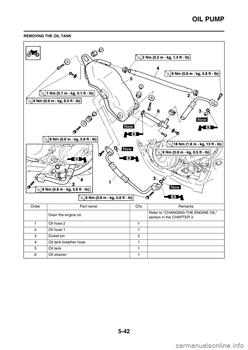
REMOVING THE OIL TANK
Order Part name Q'ty Remarks
Drain the engine oil.Refer to "CHANGING THE ENGINE OIL"
section in the CHAPTER 3.
1 Oil hose 2 1
2 Oil hose 1 1
3 Dowel pin 2
4 Oil tank breather hose 1
5 Oil tank 1
6 Oil strainer 1
Page 146 of 232
5-43
OIL PUMP
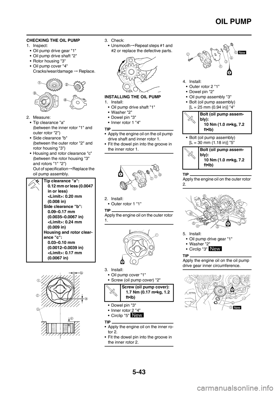
CHECKING THE OIL PUMP
1. Inspect:
• Oil pump drive gear "1"
• Oil pump drive shaft "2"
• Rotor housing "3"
• Oil pump cover "4"
Cracks/wear/damage→Replace.
2. Measure:
• Tip clearance "a"
(between the inner rotor "1" and
outer rotor "2")
• Side clearance "b"
(between the outer rotor "2" and
rotor housing "3")
• Housing and rotor clearance "c"
(between the rotor housing "3"
and rotors "1" "2")
Out of specification→Replace the
oil pump assembly.3. Check:
• Unsmooth→Repeat steps #1 and
#2 or replace the defective parts.
INSTALLING THE OIL PUMP
1. Install:
• Oil pump drive shaft "1"
• Washer "2"
• Dowel pin "3"
• Inner rotor 1 "4"
• Apply the engine oil on the oil pump
drive shaft and inner rotor 1.
• Fit the dowel pin into the groove in
the inner rotor 1.
2. Install:
• Outer rotor 1 "1"
Apply the engine oil on the outer rotor
1.
3. Install:
• Oil pump cover "1"
• Screw (oil pump cover) "2"
• Dowel pin "3"
• Inner rotor 2 "4"
• Circlip "5"
• Apply the engine oil on the inner ro-
tor 2.
• Fit the dowel pin into the groove in
the inner rotor 2.
4. Install:
• Outer rotor 2 "1"
• Dowel pin "2"
• Oil pump assembly "3"
• Bolt (oil pump assembly)
[L = 25 mm (0.94 in)] "4"
• Bolt (oil pump assembly)
[L = 30 mm (1.18 in)] "5"
Apply the engine oil on the outer rotor
2.
5. Install:
• Oil pump drive gear "1"
• Washer "2"
• Circlip "3"
Apply the engine oil on the oil pump
drive gear inner circumference.
Tip clearance "a":
0.12 mm or less (0.0047
in or less)
(0.008 in)
Side clearance "b":
0.09–0.17 mm
(0.0035–0.0067 in)
(0.009 in)
Housing and rotor clear-
ance "c":
0.03–0.10 mm
(0.0012–0.0039 in)
(0.0067 in)
Screw (oil pump cover):
1.7 Nm (0.17 m•kg, 1.2
ft•lb)
Bolt (oil pump assem-
bly):
10 Nm (1.0 m•kg, 7.2
ft•lb)
Bolt (oil pump assem-
bly):
10 Nm (1.0 m•kg, 7.2
ft•lb)
Page 150 of 232
5-47
KICK SHAFT AND SHIFT SHAFT
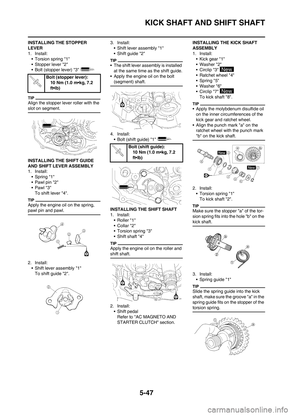
INSTALLING THE STOPPER
LEVER
1. Install:
• Torsion spring "1"
• Stopper lever "2"
• Bolt (stopper lever) "3"
Align the stopper lever roller with the
slot on segment.
INSTALLING THE SHIFT GUIDE
AND SHIFT LEVER ASSEMBLY
1. Install:
• Spring "1"
• Pawl pin "2"
•Pawl "3"
To shift lever "4".
Apply the engine oil on the spring,
pawl pin and pawl.
2. Install:
• Shift lever assembly "1"
To shift guide "2".3. Install:
• Shift lever assembly "1"
• Shift guide "2"
• The shift lever assembly is installed
at the same time as the shift guide.
• Apply the engine oil on the bolt
(segment) shaft.
4. Install:
• Bolt (shift guide) "1"
INSTALLING THE SHIFT SHAFT
1. Install:
• Roller "1"
• Collar "2"
• Torsion spring "3"
• Shift shaft "4"
Apply the engine oil on the roller and
shift shaft.
2. Install:
• Shift pedal
Refer to "AC MAGNETO AND
STARTER CLUTCH" section.INSTALLING THE KICK SHAFT
ASSEMBLY
1. Install:
• Kick gear "1"
• Washer "2"
• Circlip "3"
• Ratchet wheel "4"
• Spring "5"
• Washer "6"
• Circlip "7"
To kick shaft "8".
• Apply the molybdenum disulfide oil
on the inner circumferences of the
kick gear and ratchet wheel.
• Align the punch mark "a" on the
ratchet wheel with the punch mark
"b" on the kick shaft.
2. Install:
• Torsion spring "1"
To kick shaft "2".
Make sure the stopper "a" of the tor-
sion spring fits into the hole "b" on the
kick shaft.
3. Install:
• Spring guide "1"
Slide the spring guide into the kick
shaft, make sure the groove "a" in the
spring guide fits on the stopper of the
torsion spring.
Bolt (stopper lever):
10 Nm (1.0 m•kg, 7.2
ft•lb)
Bolt (shift guide):
10 Nm (1.0 m•kg, 7.2
ft•lb)
Page 151 of 232
5-48
KICK SHAFT AND SHIFT SHAFT
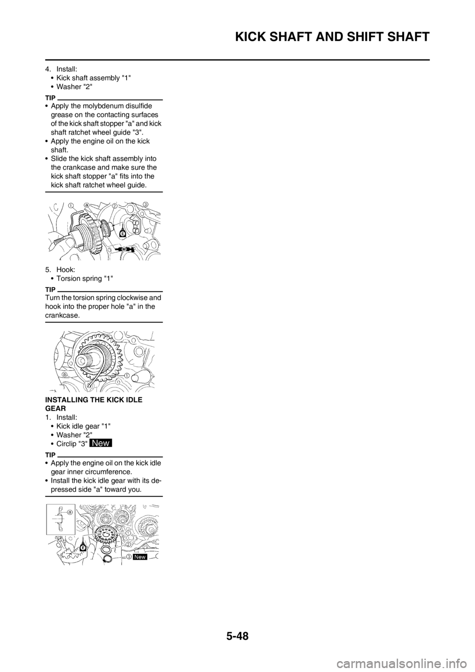
4. Install:
• Kick shaft assembly "1"
• Washer "2"
• Apply the molybdenum disulfide
grease on the contacting surfaces
of the kick shaft stopper "a" and kick
shaft ratchet wheel guide "3".
• Apply the engine oil on the kick
shaft.
• Slide the kick shaft assembly into
the crankcase and make sure the
kick shaft stopper "a" fits into the
kick shaft ratchet wheel guide.
5. Hook:
• Torsion spring "1"
Turn the torsion spring clockwise and
hook into the proper hole "a" in the
crankcase.
INSTALLING THE KICK IDLE
GEAR
1. Install:
• Kick idle gear "1"
• Washer "2"
• Circlip "3"
• Apply the engine oil on the kick idle
gear inner circumference.
• Install the kick idle gear with its de-
pressed side "a" toward you.
Page 152 of 232
5-49
AC MAGNETO AND STARTER CLUTCH
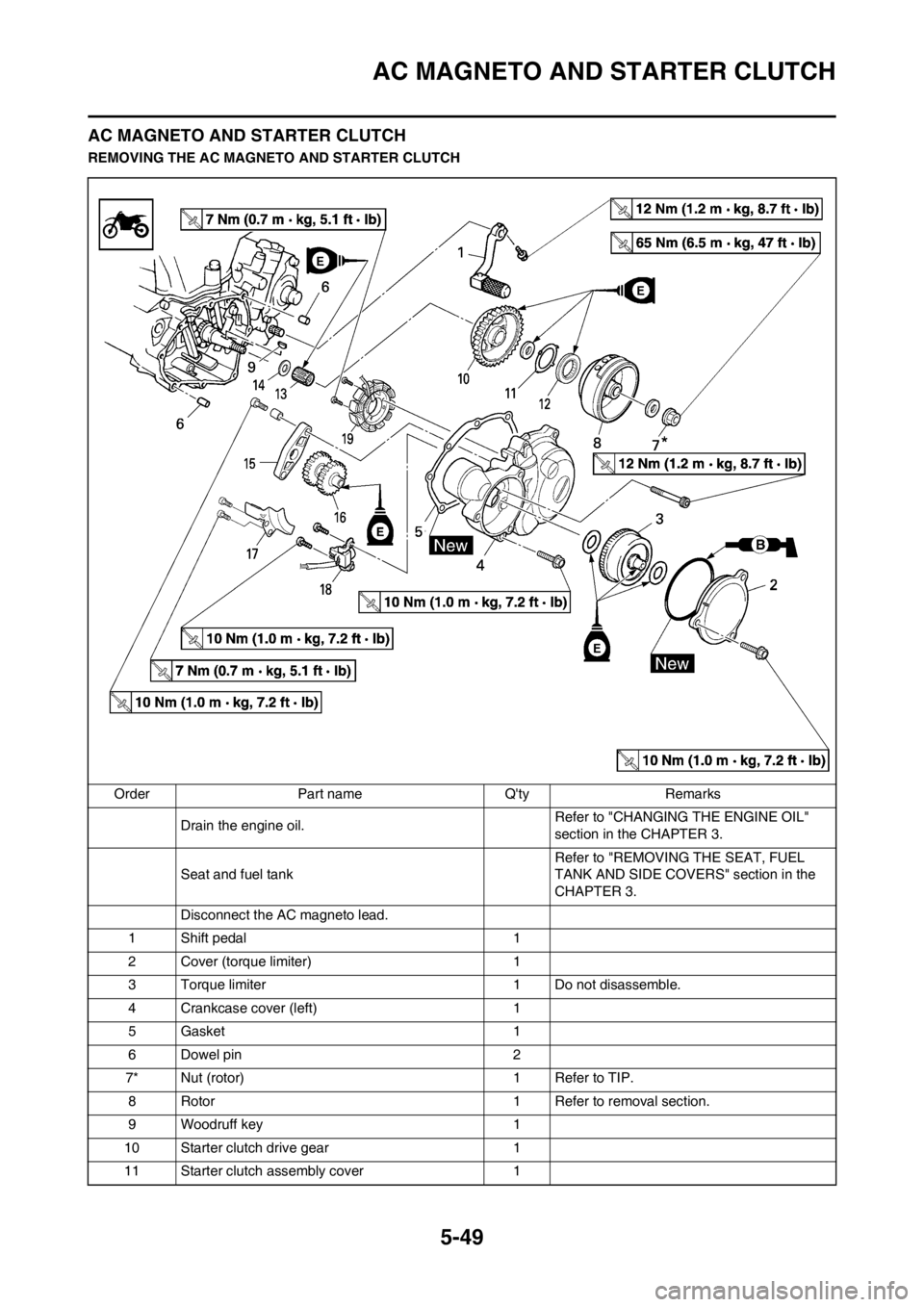
AC MAGNETO AND STARTER CLUTCH
REMOVING THE AC MAGNETO AND STARTER CLUTCH
Order Part name Q'ty Remarks
Drain the engine oil.Refer to "CHANGING THE ENGINE OIL"
section in the CHAPTER 3.
Seat and fuel tankRefer to "REMOVING THE SEAT, FUEL
TANK AND SIDE COVERS" section in the
CHAPTER 3.
Disconnect the AC magneto lead.
1 Shift pedal 1
2 Cover (torque limiter) 1
3 Torque limiter 1 Do not disassemble.
4 Crankcase cover (left) 1
5 Gasket 1
6 Dowel pin 2
7* Nut (rotor) 1 Refer to TIP.
8 Rotor 1 Refer to removal section.
9 Woodruff key 1
10 Starter clutch drive gear 1
11 Starter clutch assembly cover 1
Page 155 of 232
5-52
AC MAGNETO AND STARTER CLUTCH
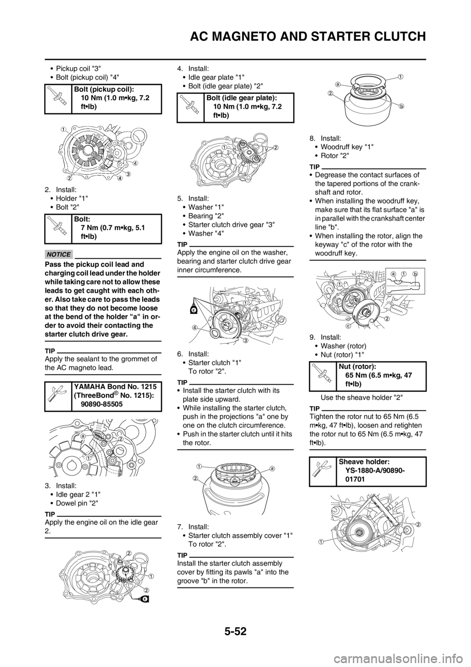
• Pickup coil "3"
• Bolt (pickup coil) "4"
2. Install:
• Holder "1"
•Bolt "2"
Pass the pickup coil lead and
charging coil lead under the holder
while taking care not to allow these
leads to get caught with each oth-
er. Also take care to pass the leads
so that they do not become loose
at the bend of the holder "a" in or-
der to avoid their contacting the
starter clutch drive gear.
Apply the sealant to the grommet of
the AC magneto lead.
3. Install:
• Idle gear 2 "1"
• Dowel pin "2"
Apply the engine oil on the idle gear
2.
4. Install:
• Idle gear plate "1"
• Bolt (idle gear plate) "2"
5. Install:
• Washer "1"
•Bearing "2"
• Starter clutch drive gear "3"
• Washer "4"
Apply the engine oil on the washer,
bearing and starter clutch drive gear
inner circumference.
6. Install:
• Starter clutch "1"
To rotor "2".
• Install the starter clutch with its
plate side upward.
• While installing the starter clutch,
push in the projections "a" one by
one on the clutch circumference.
• Push in the starter clutch until it hits
the rotor.
7. Install:
• Starter clutch assembly cover "1"
To rotor "2".
Install the starter clutch assembly
cover by fitting its pawls "a" into the
groove "b" in the rotor.
8. Install:
• Woodruff key "1"
• Rotor "2"
• Degrease the contact surfaces of
the tapered portions of the crank-
shaft and rotor.
• When installing the woodruff key,
make sure that its flat surface "a" is
in parallel with the crankshaft center
line "b".
• When installing the rotor, align the
keyway "c" of the rotor with the
woodruff key.
9. Install:
• Washer (rotor)
• Nut (rotor) "1"
Use the sheave holder "2"
Tighten the rotor nut to 65 Nm (6.5
m•kg, 47 ft•lb), loosen and retighten
the rotor nut to 65 Nm (6.5 m•kg, 47
ft•lb).
Bolt (pickup coil):
10 Nm (1.0 m•kg, 7.2
ft•lb)
Bolt:
7 Nm (0.7 m•kg, 5.1
ft•lb)
YAMAHA Bond No. 1215
(ThreeBond
® No. 1215):
90890-85505
E
Bolt (idle gear plate):
10 Nm (1.0 m•kg, 7.2
ft•lb)
E
Nut (rotor):
65 Nm (6.5 m•kg, 47
ft•lb)
Sheave holder:
YS-1880-A/90890-
01701
Page 156 of 232
![YAMAHA WR 250F 2012 Repair Manual 5-53
AC MAGNETO AND STARTER CLUTCH
10. Install:
• Dowel pin
• Gasket [crankcase cover (left)]
• Crankcase cover (left) "1"
• Bolt [crankcase cover (left)] "2"
• Bolt [crankcase cover (left) YAMAHA WR 250F 2012 Repair Manual 5-53
AC MAGNETO AND STARTER CLUTCH
10. Install:
• Dowel pin
• Gasket [crankcase cover (left)]
• Crankcase cover (left) "1"
• Bolt [crankcase cover (left)] "2"
• Bolt [crankcase cover (left)](/img/51/52308/w960_52308-155.png)
5-53
AC MAGNETO AND STARTER CLUTCH
10. Install:
• Dowel pin
• Gasket [crankcase cover (left)]
• Crankcase cover (left) "1"
• Bolt [crankcase cover (left)] "2"
• Bolt [crankcase cover (left)] "3"
Tighten the bolts in stage, using a
crisscross pattern.
11. Install:
• Washer "1"
• Torque limiter "2"
• Washer "3"
Apply the engine oil to the shaft and
washers.
12. Install:
• O-ring
• Cover (idle gear 1) "1"
•Bolt "2"
• Apply the lithium soap base grease
on the O-ring.
• Install the cover (idle gear 1) with its
mark "a" facing upward.
13. Connect:
• AC magneto lead
Refer to "CABLE ROUTING DIA-
GRAM" section in the CHAPTER
2.
14. Install:
• Shift pedal "1"
• Bolt (shift pedal) "2"
When installing the shift pedal onto
the shift shaft, be sure that the center
of the shift pedal is about 1.4 mm
(0.06 in) "a" above the top of the foot-
rest.
Bolt [crankcase cover
(left)]:
10 Nm (1.0 m•kg, 7.2
ft•lb)
Bolt [crankcase cover
(left)]:
12 Nm (1.2 m•kg, 8.7
ft•lb)
Bolt:
10 Nm (1.0 m•kg, 7.2
ft•lb)
E
Bolt (shift pedal):
12 Nm (1.2 m•kg, 8.7
ft•lb)
Page 157 of 232
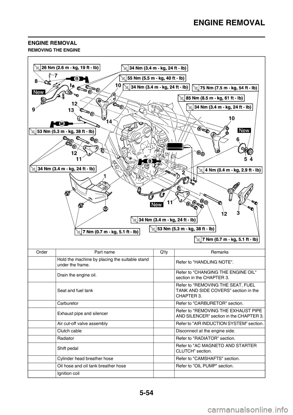
5-54
ENGINE REMOVAL
ENGINE REMOVAL
REMOVING THE ENGINE
Order Part name Q'ty Remarks
Hold the machine by placing the suitable stand
under the frame.Refer to "HANDLING NOTE".
Drain the engine oil.Refer to "CHANGING THE ENGINE OIL"
section in the CHAPTER 3.
Seat and fuel tank Refer to "REMOVING THE SEAT, FUEL
TANK AND SIDE COVERS" section in the
CHAPTER 3.
Carburetor Refer to "CARBURETOR" section.
Exhaust pipe and silencer Refer to "REMOVING THE EXHAUST PIPE
AND SILENCER" section in the CHAPTER 3.
Air cut-off valve assembly Refer to "AIR INDUCTION SYSTEM" section.
Clutch cable Disconnect at the engine side.
Radiator Refer to "RADIATOR" section.
Shift pedalRefer to "AC MAGNETO AND STARTER
CLUTCH" section.
Cylinder head breather hose Refer to "CAMSHAFTS" section.
Oil hose and oil tank breather hose Refer to "OIL PUMP" section.
Ignition coil