steering YAMAHA WR 250F 2013 User Guide
[x] Cancel search | Manufacturer: YAMAHA, Model Year: 2013, Model line: WR 250F, Model: YAMAHA WR 250F 2013Pages: 232, PDF Size: 13.36 MB
Page 66 of 232

3-7
PRE-OPERATION INSPECTION AND MAINTENANCE
PRE-OPERATION INSPECTION AND MAINTENANCE
Before riding for break-in operation or practice, make sure the machine is in good operating condition.
Before using this machine, check the following points.
GENERAL INSPECTION AND MAINTENANCE
Item Routine Page
CoolantCheck that coolant is filled up to the radiator cap. Check the cool-
ing system for leakage.P.3-11 – 12
FuelCheck that a fresh gasoline is filled in the fuel tank. Check the fuel
line for leakage.P.1-18
Engine oilCheck that the oil level is correct. Check the crankcase and oil
line for leakage.P.3-14 – 15
Gear shifter and clutchCheck that gears can be shifted correctly in order and that the
clutch operates smoothly.P.3-12 – 13
Throttle grip/HousingCheck that the throttle grip operation and free play are correctly
adjusted. Lubricate the throttle grip and housing, if necessary.P.3-13
Brakes Check the play of front brake and effect of front and rear brake. P.3-19 – 22
Drive chainCheck drive chain slack and alignment. Check that the drive chain
is lubricated properly.P.3-22 – 23
WheelsCheck for excessive wear and tire pressure. Check for loose
spokes and have no excessive play.P.3-26 – 27
SteeringCheck that the handlebar can be turned smoothly and have no ex-
cessive play.P.3-27
Front forks and rear shock
absorberCheck that they operate smoothly and there is no oil leakage.
P.3-23 – 26
Cables (wires)Check that the clutch and throttle cables move smoothly. Check
that they are not caught when the handlebars are turned or when
the front forks travel up and down.—
Exhaust pipe Check that the exhaust pipe is tightly mounted and has no cracks. P.3-10 – 11
Rear wheel sprocket Check that the rear wheel sprocket tightening bolt is not loose. P.3-22
Lubrication Check for smooth operation. Lubricate if necessary. P.3-28
Bolts and nuts Check the chassis and engine for loose bolts and nuts. P.1-20
Lead connectorsCheck that the AC magneto, CDI unit, and ignition coil are con-
nected tightly.P.1-7
SettingsIs the machine set suitably for the condition of the course and
weather or by taking into account the results of test runs before
riding? Are inspection and maintenance completely done?P.4-1 – 10
Page 86 of 232

3-27
CHASSIS
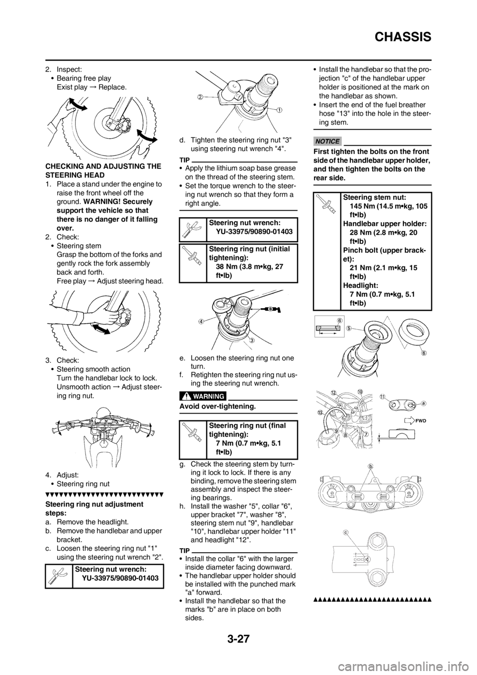
2. Inspect:
• Bearing free play
Exist play→Replace.
CHECKING AND ADJUSTING THE
STEERING HEAD
1. Place a stand under the engine to
raise the front wheel off the
ground. WARNING! Securely
support the vehicle so that
there is no danger of it falling
over.
2. Check:
• Steering stem
Grasp the bottom of the forks and
gently rock the fork assembly
back and forth.
Free play→Adjust steering head.
3. Check:
• Steering smooth action
Turn the handlebar lock to lock.
Unsmooth action→Adjust steer-
ing ring nut.
4. Adjust:
• Steering ring nut
Steering ring nut adjustment
steps:
a. Remove the headlight.
b. Remove the handlebar and upper
bracket.
c. Loosen the steering ring nut "1"
using the steering nut wrench "2".d. Tighten the steering ring nut "3"
using steering nut wrench "4".
• Apply the lithium soap base grease
on the thread of the steering stem.
• Set the torque wrench to the steer-
ing nut wrench so that they form a
right angle.
e. Loosen the steering ring nut one
turn.
f. Retighten the steering ring nut us-
ing the steering nut wrench.
Avoid over-tightening.
g. Check the steering stem by turn-
ing it lock to lock. If there is any
binding, remove the steering stem
assembly and inspect the steer-
ing bearings.
h. Install the washer "5", collar "6",
upper bracket "7", washer "8",
steering stem nut "9", handlebar
"10", handlebar upper holder "11"
and headlight "12".
• Install the collar "6" with the larger
inside diameter facing downward.
• The handlebar upper holder should
be installed with the punched mark
"a" forward.
• Install the handlebar so that the
marks "b" are in place on both
sides.• Install the handlebar so that the pro-
jection "c" of the handlebar upper
holder is positioned at the mark on
the handlebar as shown.
• Insert the end of the fuel breather
hose "13" into the hole in the steer-
ing stem.
First tighten the bolts on the front
side of the handlebar upper holder,
and then tighten the bolts on the
rear side.
Steering nut wrench:
YU-33975/90890-01403
Steering nut wrench:
YU-33975/90890-01403
Steering ring nut (initial
tightening):
38 Nm (3.8 m•kg, 27
ft•lb)
Steering ring nut (final
tightening):
7 Nm (0.7 m•kg, 5.1
ft•lb)
Steering stem nut:
145 Nm (14.5 m•kg, 105
ft•lb)
Handlebar upper holder:
28 Nm (2.8 m•kg, 20
ft•lb)
Pinch bolt (upper brack-
et):
21 Nm (2.1 m•kg, 15
ft•lb)
Headlight:
7 Nm (0.7 m•kg, 5.1
ft•lb)
Page 196 of 232

6-27
STEERING
STEERING
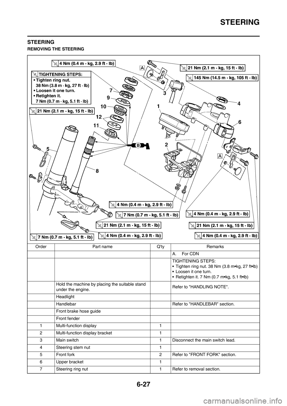
REMOVING THE STEERING
Order Part name Q'ty Remarks
A. For CDN
TIGHTENING STEPS:
• Tighten ring nut. 38 Nm (3.8 m•kg, 27 ft•lb)
• Loosen it one turn.
• Retighten it. 7 Nm (0.7 m•kg, 5.1 ft•lb)
Hold the machine by placing the suitable stand
under the engine.Refer to "HANDLING NOTE".
Headlight
Handlebar Refer to "HANDLEBAR" section.
Front brake hose guide
Front fender
1 Multi-function display 1
2 Multi-function display bracket 1
3 Main switch 1 Disconnect the main switch lead.
4 Steering stem nut 1
5 Front fork 2 Refer to "FRONT FORK" section.
6 Upper bracket 1
7 Steering ring nut 1 Refer to removal section.
Page 197 of 232

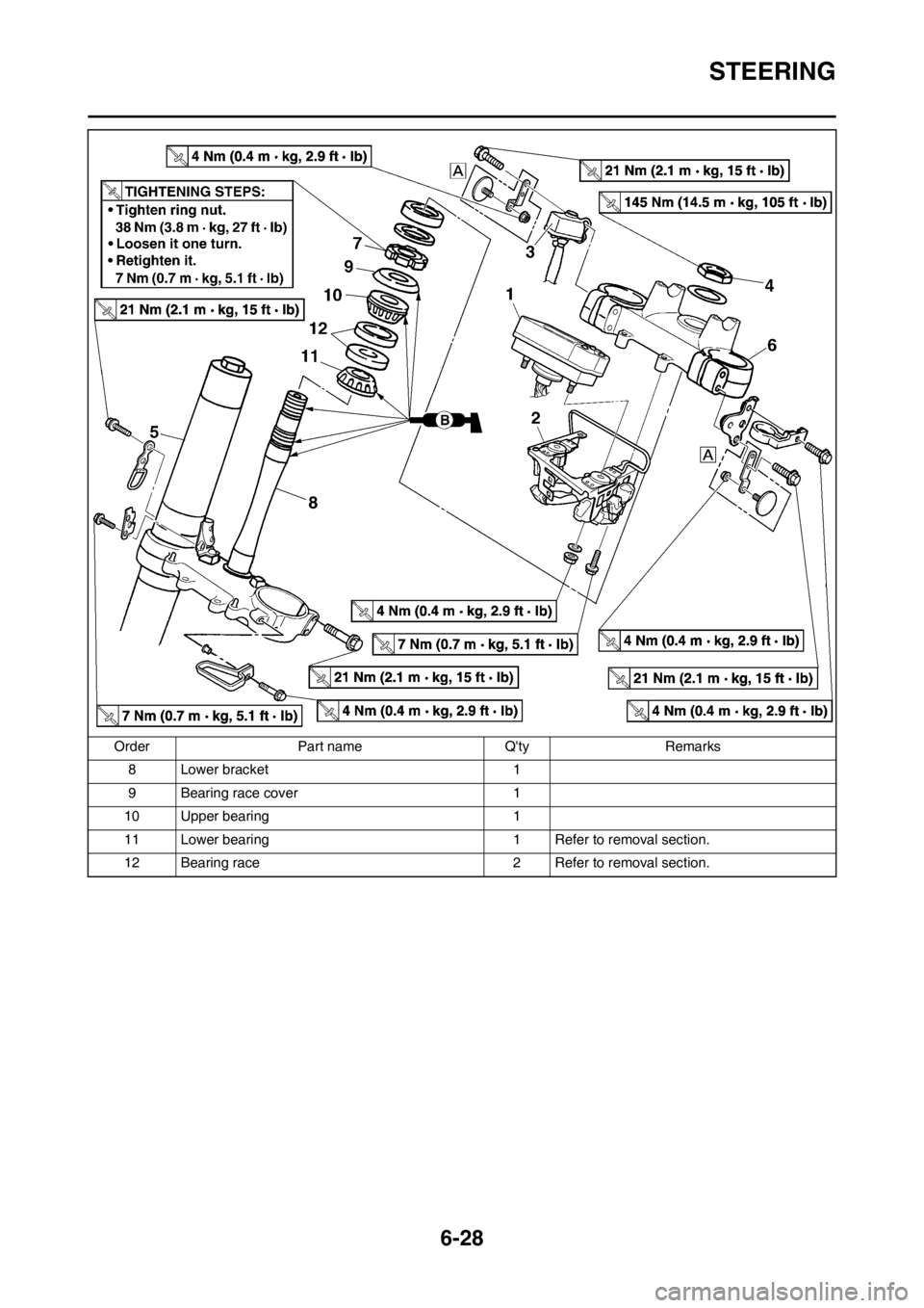
6-28
STEERING
8 Lower bracket 1
9 Bearing race cover 1
10 Upper bearing 1
11 Lower bearing 1 Refer to removal section.
12 Bearing race 2 Refer to removal section. Order Part name Q'ty Remarks
Page 198 of 232

6-29
STEERING
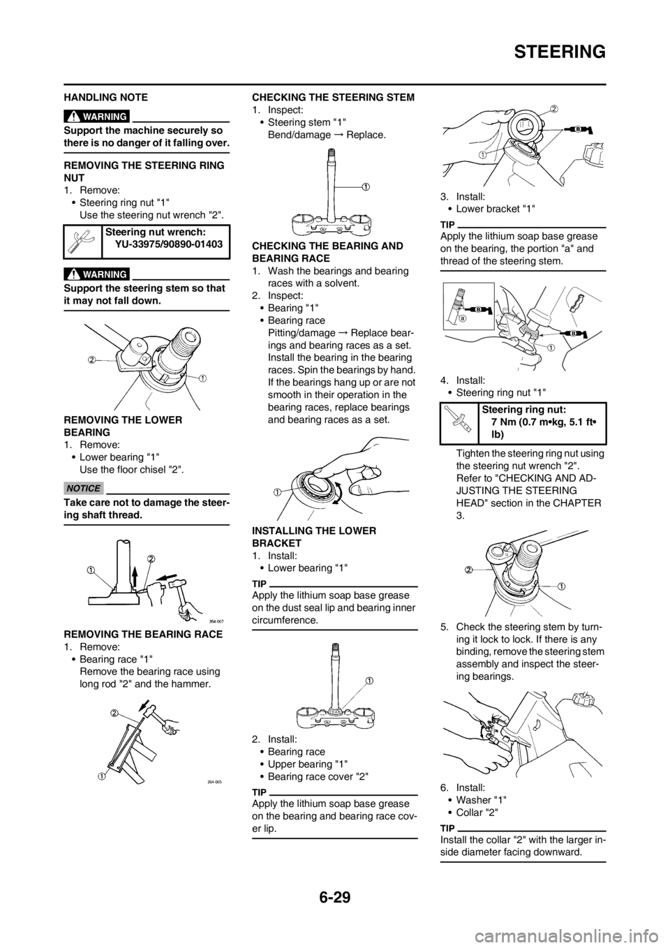
HANDLING NOTE
Support the machine securely so
there is no danger of it falling over.
REMOVING THE STEERING RING
NUT
1. Remove:
• Steering ring nut "1"
Use the steering nut wrench "2".
Support the steering stem so that
it may not fall down.
REMOVING THE LOWER
BEARING
1. Remove:
• Lower bearing "1"
Use the floor chisel "2".
Take care not to damage the steer-
ing shaft thread.
REMOVING THE BEARING RACE
1. Remove:
• Bearing race "1"
Remove the bearing race using
long rod "2" and the hammer.CHECKING THE STEERING STEM
1. Inspect:
• Steering stem "1"
Bend/damage→Replace.
CHECKING THE BEARING AND
BEARING RACE
1. Wash the bearings and bearing
races with a solvent.
2. Inspect:
•Bearing "1"
• Bearing race
Pitting/damage→Replace bear-
ings and bearing races as a set.
Install the bearing in the bearing
races. Spin the bearings by hand.
If the bearings hang up or are not
smooth in their operation in the
bearing races, replace bearings
and bearing races as a set.
INSTALLING THE LOWER
BRACKET
1. Install:
• Lower bearing "1"
Apply the lithium soap base grease
on the dust seal lip and bearing inner
circumference.
2. Install:
• Bearing race
• Upper bearing "1"
• Bearing race cover "2"
Apply the lithium soap base grease
on the bearing and bearing race cov-
er lip.
3. Install:
• Lower bracket "1"
Apply the lithium soap base grease
on the bearing, the portion "a" and
thread of the steering stem.
4. Install:
• Steering ring nut "1"
Tighten the steering ring nut using
the steering nut wrench "2".
Refer to "CHECKING AND AD-
JUSTING THE STEERING
HEAD" section in the CHAPTER
3.
5. Check the steering stem by turn-
ing it lock to lock. If there is any
binding, remove the steering stem
assembly and inspect the steer-
ing bearings.
6. Install:
• Washer "1"
•Collar "2"
Install the collar "2" with the larger in-
side diameter facing downward.
Steering nut wrench:
YU-33975/90890-01403
Steering ring nut:
7 Nm (0.7 m•kg, 5.1 ft•
lb)
Page 199 of 232

6-30
STEERING
7. Install:
• Front fork "1"
• Upper bracket "2"
• Main switch "3"
• Front brake hose guide bracket
"4"
• Front reflector (For CDN) "5"
• Nut (front reflector) (For CDN) "6"
• Front reflector bracket (For CDN)
"7"
• Temporarily tighten the pinch bolts
(lower bracket).
• Do not tighten the pinch bolts (up-
per bracket) yet.
8. Install:
• Guide (speed sensor lead) "1"
After installing the guide as shown,
pass the speed sensor lead through
the guide.
9. Install:
• Washer "1"
• Steering stem nut "2"10. After tightening the nut, check the
steering for smooth movement. If
not, adjust the steering by loosen-
ing the steering ring nut little by lit-
tle.
11. Adjust:
• Front fork top end "a"
12. Tighten:
• Pinch bolt (upper bracket) "1"
• Pinch bolt (lower bracket) "2"
Tighten the lower bracket to speci-
fied torque. If torqued too much, it
may cause the front fork to mal-
function.
13. Install:
• Multi-function display bracket "1"• Multi-function display "2"
Pass the throttle cables "3", clutch ca-
ble "4" and hot starter cable "5" be-
tween the multi-function display
bracket and upper bracket.
14. Install:
• Holder "1"
• Clamp "2"
• Install so that the marking "a" on the
speed sensor lead aligns with the
holder edge.
• Fasten the speed sensor lead to the
holder with the clamp.
Nut (front reflector) (For
CDN) :
4 Nm (0.4 m•kg, 2.9 ft•
lb)
Steering stem nut:
145 Nm (14.5 m•kg, 105
ft•lb)
Front fork top end (stan-
dard) "a":
5 mm (0.20 in)
Pinch bolt (upper brack-
et):
21 Nm (2.1 m•kg, 15
ft•lb)
Pinch bolt (lower brack-
et):
21 Nm (2.1 m•kg, 15
ft•lb)
Multi-function display
bracket:
7 Nm (0.7 m•kg, 5.1
ft•lb)
Multi-function display:
4 Nm (0.4 m•kg, 2.9
ft•lb)
Holder:
13 Nm (1.3 m•kg, 9.4
ft•lb)
Clamp:
7 Nm (0.7 m•kg, 5.1
ft•lb)