ECU YAMAHA WR 250F 2016 Owners Manual
[x] Cancel search | Manufacturer: YAMAHA, Model Year: 2016, Model line: WR 250F, Model: YAMAHA WR 250F 2016Pages: 428, PDF Size: 14.13 MB
Page 7 of 428

EAS2GB7005
SAFETY INFORMATION
THIS MACHINE IS DESIGNED STRICTLY FOR COMPETITION USE, ONLY ON A CLOSED
COURSE. It is illegal for this machine to be operated on any public street, road, or highway. Off-road
use on public lands may also be illegal. Please check local regulations before riding.
• THIS MACHINE IS TO BE OPERATED BY AN EXPERIENCED RIDER ONLY.
Do not attempt to operate this machine at maximum power until you are totally familiar with its char-
acteristics.
• THIS MACHINE IS DESIGNED TO BE RIDDEN BY THE OPERATOR ONLY.
Do not carry passengers on this machine.
• ALWAYS WEAR PROTECTIVE APPAREL.
When operating this machine, always wear an approved helmet with goggles or a face shield. Also
wear heavy boots, gloves, and protective clothing. Always wear proper fitting clothing that will not
be caught in any of the moving parts or controls of the machine.
• ALWAYS MAINTAIN YOUR MACHINE IN PROPER WORKING ORDER.
For safety and reliability, the machine must be properly maintained. Always perform the pre-oper-
ation checks indicated in this manual.
Correcting a mechanical problem before you ride may prevent an accident.
• GASOLINE IS HIGHLY FLAMMABLE.
Always turn off the engine while refueling. Take care to not spill any gasoline on the engine or ex-
haust system. Never refuel in the vicinity of an open flame, or while smoking.
• GASOLINE CAN CAUSE INJURY.
If you should swallow some gasoline, inhale excess gasoline vapors, or allow any gasoline to get
into your eyes, contact a doctor immediately. If any gasoline spills onto your skin or clothing, imme-
diately wash skin areas with soap and water, and change your clothes.
• ONLY OPERATE THE MACHINE IN AN AREA WITH ADEQUATE VENTILATION.
Never start the engine or let it run for any length of time in an enclosed area. Exhaust fumes are
poisonous. These fumes contain carbon monoxide, which by itself is odorless and colorless. Car-
bon monoxide is a dangerous gas which can cause unconsciousness or can be lethal.
• PARK THE MACHINE CAREFULLY; TURN OFF THE ENGINE.
Always turn off the engine if you are going to leave the machine. Do not park the machine on a slope
or soft ground as it may fall over.
• THE ENGINE, EXHAUST PIPE AND MUFFLER WILL BE VERY HOT AFTER THE ENGINE HAS
BEEN RUN.
Be careful not to touch them or to allow any clothing item to contact them during inspection or repair.
• PROPERLY SECURE THE MACHINE BEFORE TRANSPORTING IT.
For safety, drain the gasoline from the fuel tank before transporting the vehicle.
Page 24 of 428
BASIC SERVICE INFORMATION
1-10
ECA
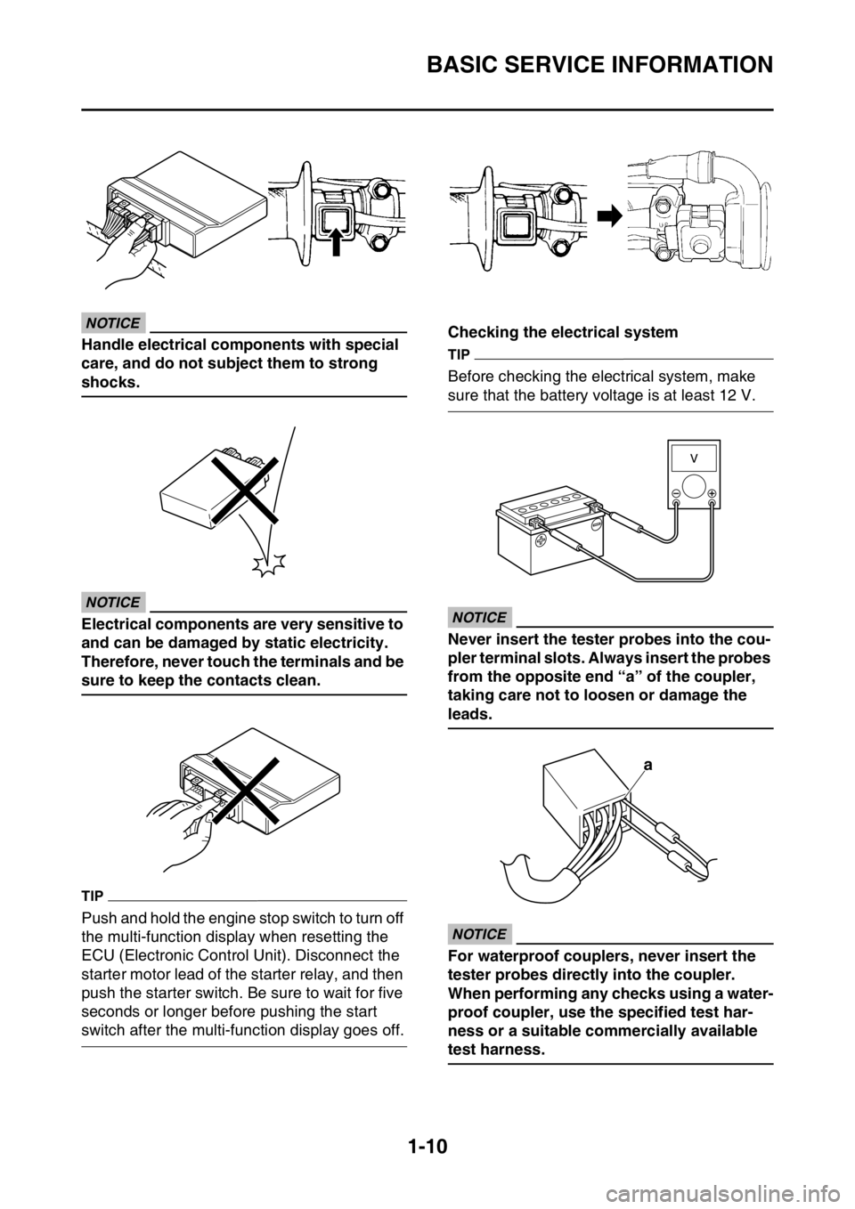
NOTICE
Handle electrical components with special
care, and do not subject them to strong
shocks.
ECA
NOTICE
Electrical components are very sensitive to
and can be damaged by static electricity.
Therefore, never touch the terminals and be
sure to keep the contacts clean.
TIP
Push and hold the engine stop switch to turn off
the multi-function display when resetting the
ECU (Electronic Control Unit). Disconnect the
starter motor lead of the starter relay, and then
push the starter switch. Be sure to wait for five
seconds or longer before pushing the start
switch after the multi-function display goes off.Checking the electrical system
TIP
Before checking the electrical system, make
sure that the battery voltage is at least 12 V.
ECA
NOTICE
Never insert the tester probes into the cou-
pler terminal slots. Always insert the probes
from the opposite end “a” of the coupler,
taking care not to loosen or damage the
leads.
ECA
NOTICE
For waterproof couplers, never insert the
tester probes directly into the coupler.
When performing any checks using a water-
proof coupler, use the specified test har-
ness or a suitable commercially available
test harness.
a
Page 25 of 428
BASIC SERVICE INFORMATION
1-11
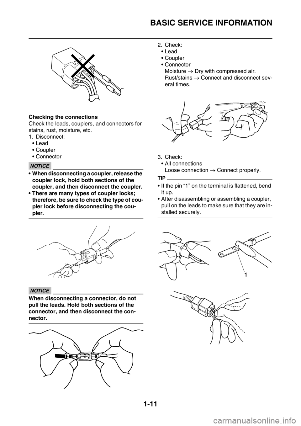
Checking the connections
Check the leads, couplers, and connectors for
stains, rust, moisture, etc.
1. Disconnect:
• Lead
• Coupler
• Connector
ECA
NOTICE
• When disconnecting a coupler, release the
coupler lock, hold both sections of the
coupler, and then disconnect the coupler.
• There are many types of coupler locks;
therefore, be sure to check the type of cou-
pler lock before disconnecting the cou-
pler.
ECA
NOTICE
When disconnecting a connector, do not
pull the leads. Hold both sections of the
connector, and then disconnect the con-
nector.2. Check:
• Lead
• Coupler
• Connector
Moisture Dry with compressed air.
Rust/stains Connect and disconnect sev-
eral times.
3. Check:
• All connections
Loose connection Connect properly.
TIP
• If the pin “1” on the terminal is flattened, bend
it up.
• After disassembling or assembling a coupler,
pull on the leads to make sure that they are in-
stalled securely.
1
Page 26 of 428
BASIC SERVICE INFORMATION
1-12
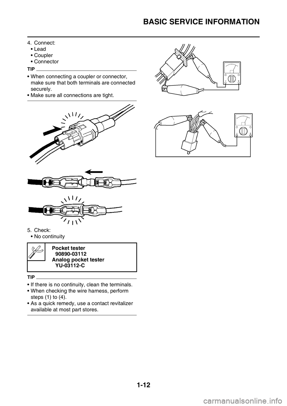
4. Connect:
• Lead
• Coupler
• Connector
TIP
• When connecting a coupler or connector,
make sure that both terminals are connected
securely.
• Make sure all connections are tight.
5. Check:
• No continuity
TIP
• If there is no continuity, clean the terminals.
• When checking the wire harness, perform
steps (1) to (4).
• As a quick remedy, use a contact revitalizer
available at most part stores.Pocket tester
90890-03112
Analog pocket tester
YU-03112-C
Page 30 of 428
SPECIAL TOOLS
1-16
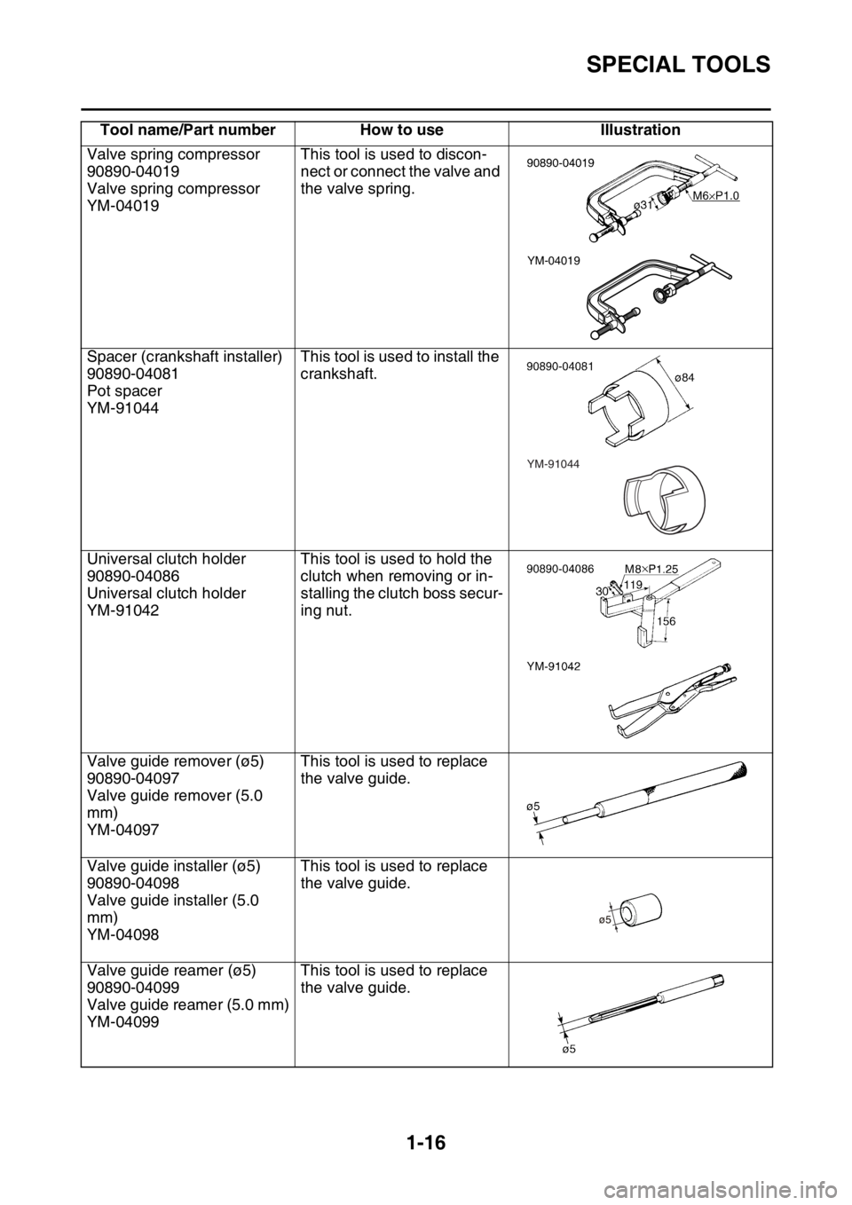
Valve spring compressor
90890-04019
Valve spring compressor
YM-04019This tool is used to discon-
nect or connect the valve and
the valve spring.
Spacer (crankshaft installer)
90890-04081
Pot spacer
YM-91044This tool is used to install the
crankshaft.
Universal clutch holder
90890-04086
Universal clutch holder
YM-91042This tool is used to hold the
clutch when removing or in-
stalling the clutch boss secur-
ing nut.
Valve guide remover (ø5)
90890-04097
Valve guide remover (5.0
mm)
YM-04097This tool is used to replace
the valve guide.
Valve guide installer (ø5)
90890-04098
Valve guide installer (5.0
mm)
YM-04098This tool is used to replace
the valve guide.
Valve guide reamer (ø5)
90890-04099
Valve guide reamer (5.0 mm)
YM-04099This tool is used to replace
the valve guide. Tool name/Part number How to use Illustration
YM-04019
YM-91044
Page 33 of 428
CONTROL FUNCTIONS
1-19
EAS2GB7029
CONTROL FUNCTIONS
EAS2GB7030INDICATOR LIGHTS AND WARNING
LIGHTS
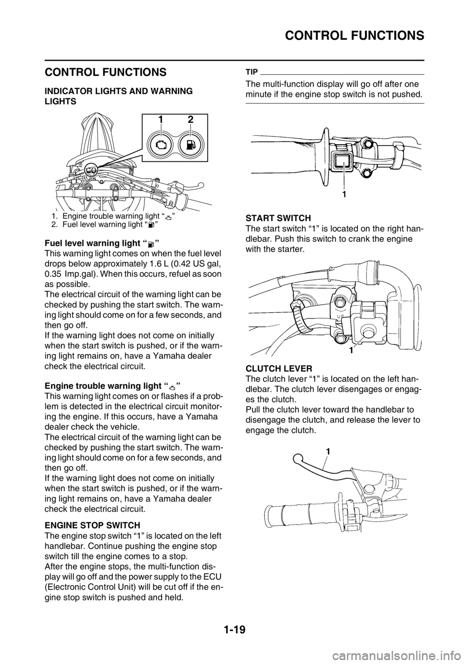
Fuel level warning light “ ”
This warning light comes on when the fuel level
drops below approximately 1.6 L (0.42 US gal,
0.35 Imp.gal). When this occurs, refuel as soon
as possible.
The electrical circuit of the warning light can be
checked by pushing the start switch. The warn-
ing light should come on for a few seconds, and
then go off.
If the warning light does not come on initially
when the start switch is pushed, or if the warn-
ing light remains on, have a Yamaha dealer
check the electrical circuit.
Engine trouble warning light “ ”
This warning light comes on or flashes if a prob-
lem is detected in the electrical circuit monitor-
ing the engine. If this occurs, have a Yamaha
dealer check the vehicle.
The electrical circuit of the warning light can be
checked by pushing the start switch. The warn-
ing light should come on for a few seconds, and
then go off.
If the warning light does not come on initially
when the start switch is pushed, or if the warn-
ing light remains on, have a Yamaha dealer
check the electrical circuit.
EAS2GB7031ENGINE STOP SWITCH
The engine stop switch “1” is located on the left
handlebar. Continue pushing the engine stop
switch till the engine comes to a stop.
After the engine stops, the multi-function dis-
play will go off and the power supply to the ECU
(Electronic Control Unit) will be cut off if the en-
gine stop switch is pushed and held.
TIP
The multi-function display will go off after one
minute if the engine stop switch is not pushed.
EAS2GB7032START SWITCH
The start switch “1” is located on the right han-
dlebar. Push this switch to crank the engine
with the starter.
EAS2GB7033CLUTCH LEVER
The clutch lever “1” is located on the left han-
dlebar. The clutch lever disengages or engag-
es the clutch.
Pull the clutch lever toward the handlebar to
disengage the clutch, and release the lever to
engage the clutch.
1. Engine trouble warning light “ ”
2. Fuel level warning light “ ”
12
Page 68 of 428
TIGHTENING TORQUES
2-15
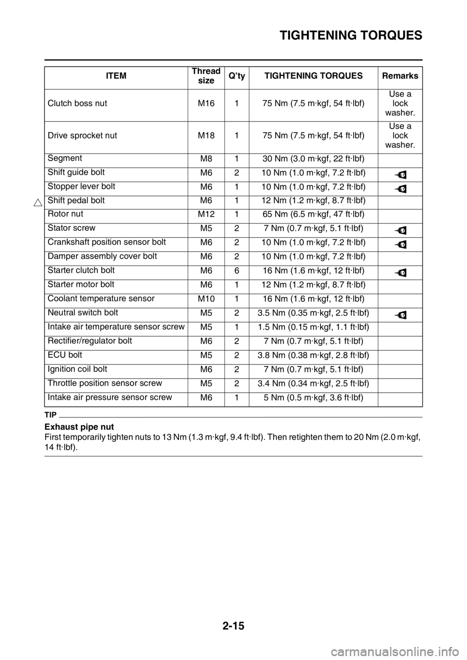
TIP
Exhaust pipe nut
First temporarily tighten nuts to 13 Nm (1.3 m·kgf, 9.4 ft·lbf). Then retighten them to 20 Nm (2.0 m·kgf,
14 ft·lbf).Clutch boss nut M16 1 75 Nm (7.5 m·kgf, 54 ft·lbf)Use a
lock
washer.
Drive sprocket nut M18 1 75 Nm (7.5 m·kgf, 54 ft·lbf)Use a
lock
washer.
Segment
M8 1 30 Nm (3.0 m·kgf, 22 ft·lbf)
Shift guide bolt
M6 2 10 Nm (1.0 m·kgf, 7.2 ft·lbf)
Stopper lever bolt
M6 1 10 Nm (1.0 m·kgf, 7.2 ft·lbf)
Shift pedal bolt M6 1 12 Nm (1.2 m·kgf, 8.7 ft·lbf)
Rotor nut
M12 1 65 Nm (6.5 m·kgf, 47 ft·lbf)
Stator screw
M5 2 7 Nm (0.7 m·kgf, 5.1 ft·lbf)
Crankshaft position sensor bolt
M6 2 10 Nm (1.0 m·kgf, 7.2 ft·lbf)
Damper assembly cover bolt
M6 2 10 Nm (1.0 m·kgf, 7.2 ft·lbf)
Starter clutch bolt
M6 6 16 Nm (1.6 m·kgf, 12 ft·lbf)
Starter motor bolt
M6 1 12 Nm (1.2 m·kgf, 8.7 ft·lbf)
Coolant temperature sensor
M10 1 16 Nm (1.6 m·kgf, 12 ft·lbf)
Neutral switch bolt
M5 2 3.5 Nm (0.35 m·kgf, 2.5 ft·lbf)
Intake air temperature sensor screw
M5 1 1.5 Nm (0.15 m·kgf, 1.1 ft·lbf)
Rectifier/regulator bolt
M6 2 7 Nm (0.7 m·kgf, 5.1 ft·lbf)
ECU bolt
M5 2 3.8 Nm (0.38 m·kgf, 2.8 ft·lbf)
Ignition coil bolt
M6 2 7 Nm (0.7 m·kgf, 5.1 ft·lbf)
Throttle position sensor screw
M5 2 3.4 Nm (0.34 m·kgf, 2.5 ft·lbf)
Intake air pressure sensor screw
M6 1 5 Nm (0.5 m·kgf, 3.6 ft·lbf) ITEMThread
sizeQ’ty TIGHTENING TORQUES Remarks
LT
LT
LT
LT
LT
LT
Page 87 of 428

CABLE ROUTING DIAGRAM
2-34
1. Clamp
2. Cylinder head breather hose
3. Throttle position sensor lead
4. Joint coupler
5. Intake air temperature sensor coupler
6. Intake air pressure sensor lead
7. Wire harness
8. Injector lead
9. Throttle body
10. Injector coupler
11. Starter motor lead
12. Plastic band
13. Fuel sender coupler
14. High tension cord
15. Spark plug cap
16. Cylinder head cover
17. Fuel hose
18. Fuel sender
19. Sub-wire harness
20. Crankcase breather hose
21. Radiator breather hose
22. Radiator hose
23. Down tube
24. Starter motor
25. Neutral switch lead
26. AC magneto lead
27. Clutch cable
28. Radiator
29. Air filter case breather hose
30. Breather hose clamp
31. Grommet (high tension cord)
32. ECU
33. Air filter case
34. Sub-wire harness coupler
35. Engine bracket
A. Fix the wire harness, clutch switch lead and start
switch lead by the plastic clamp, and insert the
projection of the plastic clamp into the hole in the
sheet metal of the radiator.
B. Route each lead so that the leads are not pinched
between the tank rail and air filter joint.
C. Insert the projection of the wire harness into the
hole in the frame.
D. Route the cylinder head breather hose without it
crossing the starter motor lead.
E. Pass the cylinder head breather hose between
the throttle cable and rectifier/regulator lead.
F. Connect the sub-wire harness to the wire har-
ness.
G. Pass the high tension cord above the fuel hose.
H. ±10°
I. Install the spark plug cap with this facing the right
of the vehicle.
J. Push the spark plug cap home, where there shall
be no gap between it and the cylinder head cover.
K. Pass the radiator breather hose between the
down tubes.
L. 50±3 mm (2.0±0.12 in)
M. Apply adhesive to the slit and inside of the grom-
met, and then fix the grommet according to the
specified dimensions.
N. Pass the sub-wire harness between the ECU and
the air filter case.
O. Insert the coupler of the sub-wire harness into the
rib of the air filter case.
P. Route the radiator breather hose through be-
tween the radiator hose, down tube and engine
bracket.
Page 91 of 428

CABLE ROUTING DIAGRAM
2-38
1. Battery negative lead
2. Fuel hose
3. Fuel pump coupler
4. Fuel pump lead
5. Resistor
6. Resistor coupler
7. Battery positive lead
8. Lean angle sensor
9. Starter motor lead
10. Radiator fan motor relay (blue tape)
11. Main relay (red tape)
12. Wire harness
13. Ground lead coupler
14. Starter relay coupler
15. Starter relay
16. Cross member
17. Diode
18. Taillight lead
19. Clamp
20. Fuel tank
21. Damper
22. Rear frame
23. Side cover 6
24. Plastic locking tie
A. After connecting the fuel pump coupler, attach
the coupler cover.
B. Pass the fuel hose to the front of the battery.
C. Route the resistor lead to the outside of the leads.
D. Connect the battery positive lead to the starter re-
lay terminal (in the left side of the vehicle).
E. Insert the protruding end of the wire harness into
the battery bracket hole and holder plate hole.
F. After connecting the negative lead coupler, place
it on the right side of the battery.
G. After installing the plastic cover to the starter re-
lay, connect the starter relay coupler.
H. Route the diode under the cross member and
place it on top of the rear fender.
I. Secure the two ends of the taillight coupler with
the starter motor lead.
J. Route the taillight lead so that it does not slack at
the rear of the vehicle.
K. Clamp the taillight lead and insert the clip into the
rear fender. Clamp it so that the lock faces in-
ward, and then cut off the excess end.
L. Route the battery positive lead under the cross
member.
M. Lower end of the rear frame
N. Clamp it so that the lock of the plastic locking tie
faces downward, insert the end into the rear
frame and side cover 6, and then cut off the ex-
cess end. After cutting off the excess end, make
sure that the plastic locking tie does not protrude
from the lower end of the rear frame.
O. Clamp it so that the lock of the plastic locking tie
faces downward, and then pass the end between
the fuel hose and rear frame.
P. Clamp the wire harness at the position of the
white tape.
Page 109 of 428

PRE-OPERATION INSPECTION AND MAINTENANCE
3-9
EAS2GB7079
PRE-OPERATION INSPECTION AND MAINTENANCE
Before riding for break-in operation, practice or a race, make sure the machine is in good operating
condition.
Before using this machine, check the following points.
EAS2GB7080GENERAL INSPECTION AND MAINTENANCE
TIP
Perform usual maintenance enough so that, in the race course, a confirmation of that and simple set-
ting adjustments may only be left, in order to get enough time to use effectively.ITEM inspect Page
CoolantCheck that coolant is filled up to the radiator cap.
Check the cooling system for leakage.3-10 – 12
FuelCheck that a fresh gasoline is filled in the fuel tank.
Check the fuel line for leakage.1-30
Engine oilCheck that the oil level is correct. Check the crank-
case and oil line for leakage.3-16 – 18
Gear shifter and clutchCheck that gears can be shifted correctly in order and
that the clutch operates smoothly.3-12 – 13
Throttle grip/HousingCheck that the throttle grip operation and free play
are correctly adjusted. Lubricate the throttle grip and
housing, if necessary.3-13 – 14
BrakesCheck the play of front brake and effect of front and
rear brake.3-24 – 30
Drive chainCheck drive chain slack and alignment. Check that
the drive chain is lubricated properly.3-30
5-69 – 70
WheelsCheck for excessive wear and tire pressure. Check
for loose spokes and have no excessive play.3-35 – 36
SteeringCheck that the handlebar can be turned smoothly and
have no excessive play.3-36 – 37
Front forks and rear
shock absorberCheck that they operate smoothly and there is no oil
leakage.3-31 – 35
Cables (wires)Check that the clutch and throttle cables move
smoothly. Check that they are not caught when the
handlebars are turned or when the front forks travel
up and down.—
Exhaust pipeCheck that the exhaust pipe is tightly mounted and
has no cracks.3-15 – 16
Rear wheel sprocketCheck that the rear wheel sprocket tightening bolt is
not loose.5-10 – 11
LubricationCheck for smooth operation. Lubricate if necessary. 3-13
3-37 – 38
Bolts and nutsCheck the chassis and engine for loose bolts and
nuts.1-34 – 35
Lead connectorsCheck that the AC magneto, ECU and ignition coil are
connected tightly.1-9 – 12
SettingsIs the machine set suitably for the condition of the rac-
ing course and weather or by taking into account the
results of test runs before racing? Are inspection and
maintenance completely done?4-1 – 8