transmission oil YAMAHA WR 250F 2016 Owners Manual
[x] Cancel search | Manufacturer: YAMAHA, Model Year: 2016, Model line: WR 250F, Model: YAMAHA WR 250F 2016Pages: 428, PDF Size: 14.13 MB
Page 44 of 428
STARTING AND BREAK-IN
1-30
EAS2GB7048
STARTING AND BREAK-IN
EAS2GB7049FUEL
Always use the recommended fuel as stated
below. Also, be sure to use new gasoline the
day of a race.
ECA
NOTICE
Use only unleaded gasoline. The use of
leaded gasoline will cause severe damage
to the engine internal parts such as valves,
piston rings, and exhaust system, etc.
TIP
Your Yamaha engine has been designed to use
premium unleaded gasoline with a pump oc-
tane number [(R+M)/2] of 91 or higher, or a re-
search octane number of 95 or higher. If
knocking (or pinging) occurs, use a gasoline of
a different brand.
EWA
WARNING
• For refueling, be sure to stop the engine
and use enough care not to spill any fuel.
Also be sure to avoid refueling close to a
fire.
• Refuel after the engine, exhaust pipe, etc.
have cooled off.
Gasohol (For USA and Canada)
There are two types of gasohol: gasohol con-
taining ethanol and that containing methanol.
Gasohol containing ethanol can be used if the
ethanol content does not exceed 10%. Gasohol
containing methanol is not recommended by
Yamaha because it can cause damage to the
fuel system or vehicle performance problems.
EAS2GB7050HANDLING NOTEEWA
WARNING
Never start or run the engine in a closed ar-
ea. The exhaust fumes are poisonous; they
can cause loss of consciousness and death
in a very short time. Always operate the ma-
chine in a well-ventilated area.
ECA
NOTICE
• Unlike a two-stroke engine, this engine
cannot be kick started when the throttle is
open because the kickstarter may kick
back. Also, if the throttle is open the air/
fuel mixture may be too lean for the engine
to start.
• Before starting the machine, perform the
checks in the pre-operation check list.
EAS2GB7051AIR FILTER MAINTENANCE
According to “CLEANING THE AIR FILTER
ELEMENT” section in the CHAPTER 3, apply
the foam-air-filter oil or its equivalent to the ele-
ment. (Excess oil in the element may adversely
affect engine starting.)
EAS2GB7052STARTING A COLD ENGINEECA
NOTICE
For maximum engine life, never accelerate
hard when the engine is cold!
In order for the ignition circuit cut-off system to
enable starting, one of the following conditions
must be met:
• The transmission is in the neutral position.
• The transmission is in gear with the clutch le-
ver pulled.
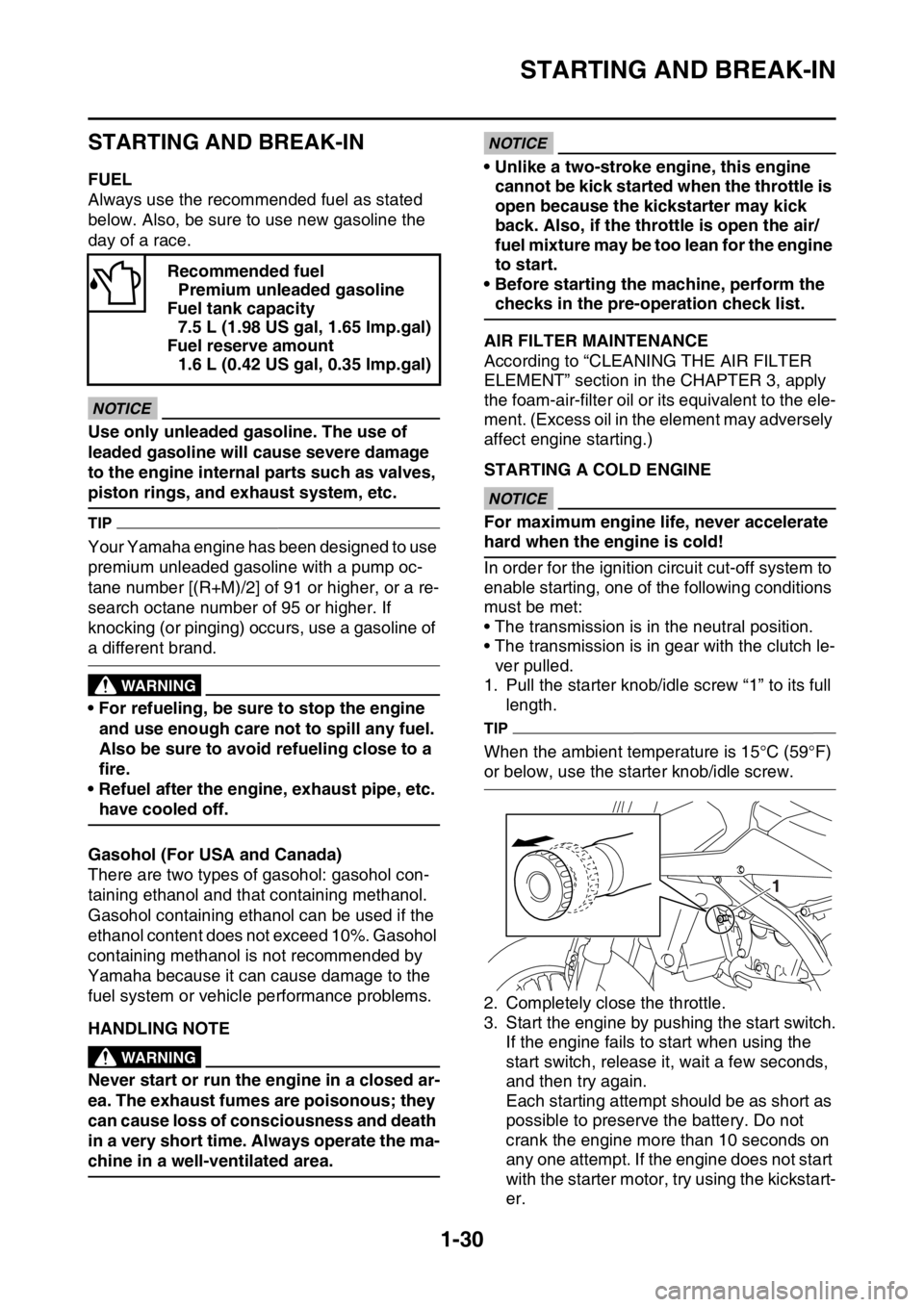
1. Pull the starter knob/idle screw “1” to its full
length.
TIP
When the ambient temperature is 15°C (59°F)
or below, use the starter knob/idle screw.
2. Completely close the throttle.
3. Start the engine by pushing the start switch.
If the engine fails to start when using the
start switch, release it, wait a few seconds,
and then try again.
Each starting attempt should be as short as
possible to preserve the battery. Do not
crank the engine more than 10 seconds on
any one attempt. If the engine does not start
with the starter motor, try using the kickstart-
er. Recommended fuel
Premium unleaded gasoline
Fuel tank capacity
7.5 L (1.98 US gal, 1.65 lmp.gal)
Fuel reserve amount
1.6 L (0.42 US gal, 0.35 lmp.gal)
1
Page 58 of 428

ENGINE SPECIFICATIONS
2-5
Balancer
Balancer drive method Gear
Clutch
Clutch type Wet, multiple-disc
Clutch release method Inner push, cam push
Clutch lever free play 7.0–12.0 mm (0.28–0.47 in)
Friction plate thickness 2.90–3.10 mm (0.114–0.122 in)
Wear limit 2.85 mm (0.112 in)
Plate quantity 9 pcs
Clutch plate thickness 1.10–1.30 mm (0.043–0.051 in)
Plate quantity 8 pcs
Warpage limit 0.10 mm (0.004 in)
Clutch spring free length 47.80 mm (1.88 in)
Limit 46.80 mm (1.84 in)
Spring quantity 5 pcs
Push rod bending limit 0.10 mm (0.004 in)
Transmission
Transmission type Constant mesh 6-speed
Primary reduction system Spur gear
Primary reduction ratio 3.353 (57/17)
Final drive Chain
Secondary reduction ratio 3.846 (50/13)
Operation Left foot operation
Gear ratio
1st 2.385 (31/13)
2nd 1.813 (29/16)
3rd 1.444 (26/18)
4th 1.143 (24/21)
5th 0.957 (22/23)
6th 0.815 (22/27)
Main axle runout limit 0.08 mm (0.0032 in)
Drive axle runout limit 0.08 mm (0.0032 in)
Shifting mechanism
Shift mechanism type Shift drum and guide bar
Shift fork guide bar bending limit 0.050 mm (0.0020 in)
Shift fork thickness 4.85 mm (0.1909 in)
Decompression device
Device type Auto decomp
Air filter
Air filter element Wet element
Air filter oil grade Foam air-filter oil
Fuel pump
Pump type Electrical
Fuel injector
Model/quantity 30NA-FZ31/1
Resistance 12
Page 73 of 428
LUBRICATION POINTS AND LUBRICANT TYPES
2-20
EAS2GB7068
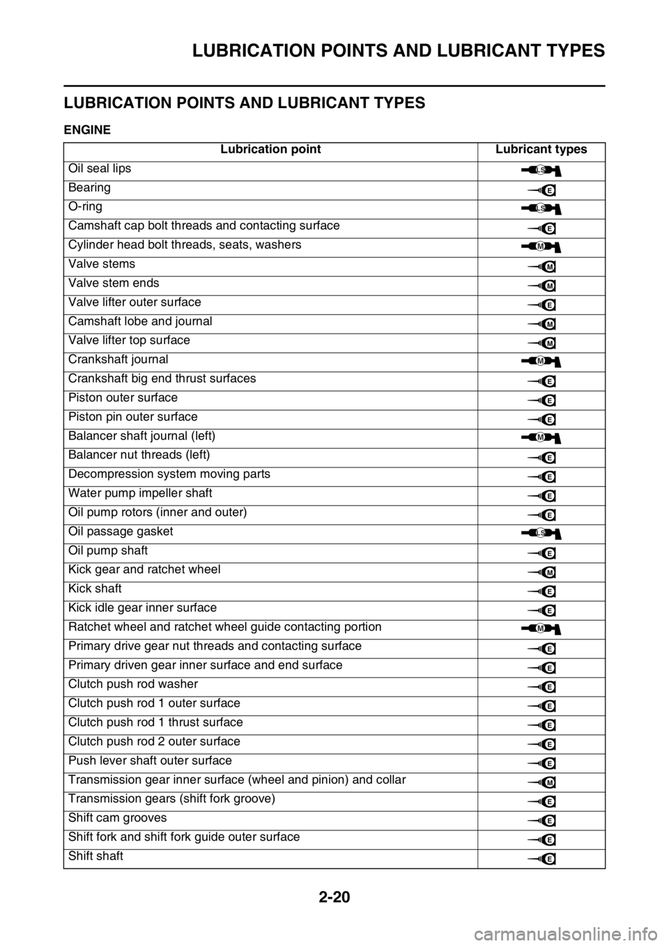
LUBRICATION POINTS AND LUBRICANT TYPES
EAS2GB7069ENGINE
Lubrication point Lubricant types
Oil seal lips
Bearing
O-ring
Camshaft cap bolt threads and contacting surface
Cylinder head bolt threads, seats, washers
Valve stems
Valve stem ends
Valve lifter outer surface
Camshaft lobe and journal
Valve lifter top surface
Crankshaft journal
Crankshaft big end thrust surfaces
Piston outer surface
Piston pin outer surface
Balancer shaft journal (left)
Balancer nut threads (left)
Decompression system moving parts
Water pump impeller shaft
Oil pump rotors (inner and outer)
Oil passage gasket
Oil pump shaft
Kick gear and ratchet wheel
Kick shaft
Kick idle gear inner surface
Ratchet wheel and ratchet wheel guide contacting portion
Primary drive gear nut threads and contacting surface
Primary driven gear inner surface and end surface
Clutch push rod washer
Clutch push rod 1 outer surface
Clutch push rod 1 thrust surface
Clutch push rod 2 outer surface
Push lever shaft outer surface
Transmission gear inner surface (wheel and pinion) and collar
Transmission gears (shift fork groove)
Shift cam grooves
Shift fork and shift fork guide outer surface
Shift shaft
LS
E
LS
E
M
M
M
E
M
M
M
E
E
E
M
E
E
E
E
LS
E
M
E
E
M
E
E
E
E
E
E
E
M
E
E
E
E
Page 130 of 428
CHASSIS
3-30
WARNING
• Use only the designated brake fluid. Other
brake fluids may cause the rubber seals to
deteriorate, causing leakage and poor
brake performance.
• Refill with the same type of brake fluid that
is already in the system. Mixing brake flu-
ids may result in a harmful chemical reac-
tion, leading to poor brake performance.
• When refilling, be careful that water does
not enter the brake fluid reservoir. Water
will significantly lower the boiling point of
the brake fluid and could cause vapor
lock.
ECA
NOTICE
Brake fluid may damage painted surfaces
and plastic parts. Therefore, always clean
up any spilt brake fluid immediately.
EAS2GB7110ADJUSTING THE DRIVE CHAIN SLACKECA
NOTICE
A drive chain that is too tight will overload
the engine and other vital parts, and one
that is too loose can skip and damage the
swingarm or cause an accident. Therefore,
keep the drive chain slack within the speci-
fied limits.
1. Use a suitable stand to raise the rear wheel
off the ground.
EWA
WARNING
Securely support the vehicle so that there is
no danger of it falling over.
2. Shift the transmission into the neutral posi-
tion.
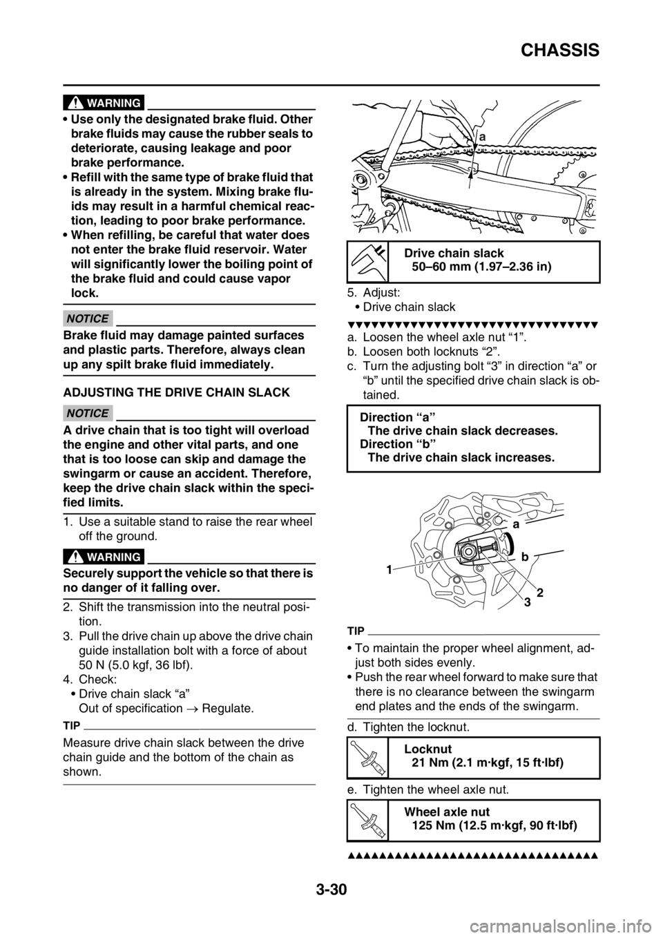
3. Pull the drive chain up above the drive chain
guide installation bolt with a force of about
50 N (5.0 kgf, 36 lbf).
4. Check:
• Drive chain slack “a”
Out of specification Regulate.
TIP
Measure drive chain slack between the drive
chain guide and the bottom of the chain as
shown.5. Adjust:
• Drive chain slack
▼▼▼▼▼▼▼▼▼▼▼▼▼▼▼▼▼▼▼▼▼▼▼▼▼▼▼▼▼▼▼▼
a. Loosen the wheel axle nut “1”.
b. Loosen both locknuts “2”.
c. Turn the adjusting bolt “3” in direction “a” or
“b” until the specified drive chain slack is ob-
tained.
TIP
• To maintain the proper wheel alignment, ad-
just both sides evenly.
• Push the rear wheel forward to make sure that
there is no clearance between the swingarm
end plates and the ends of the swingarm.
d. Tighten the locknut.
e. Tighten the wheel axle nut.
▲▲▲▲▲▲▲▲▲▲▲▲▲▲▲▲▲▲▲▲▲▲▲▲▲▲▲▲▲▲▲▲
Drive chain slack
50–60 mm (1.97–2.36 in)
Direction “a”
The drive chain slack decreases.
Direction “b”
The drive chain slack increases.
Locknut
21 Nm (2.1 m·kgf, 15 ft·lbf)
Wheel axle nut
125 Nm (12.5 m·kgf, 90 ft·lbf)
a
1
32
a
b
T R..
T R..
Page 229 of 428

GENERATOR AND STARTER CLUTCH....................................................... 6-62
REMOVING THE GENERATOR .............................................................. 6-64
CHECKING THE STARTER CLUTCH ..................................................... 6-64
INSTALLING THE STARTER CLUTCH ................................................... 6-65
INSTALLING THE GENERATOR............................................................. 6-65
CRANKCASE................................................................................................. 6-68
DISASSEMBLING THE CRANKCASE..................................................... 6-71
REMOVING THE CRANKCASE BEARING ............................................. 6-71
CHECKING THE TIMING CHAIN, TIMING CHAIN GUIDE,
OIL STRAINER ........................................................................................ 6-71
CHECKING THE CRANKCASE ............................................................... 6-71
INSTALLING THE OIL SEAL................................................................... 6-72
ASSEMBLING THE CRANKCASE........................................................... 6-72
CRANKSHAFT ASSEMBLY AND BALANCER SHAFT............................... 6-73
REMOVING THE CRANKSHAFT ASSEMBLY ........................................ 6-74
CHECKING THE CRANKSHAFT ASSEMBLY......................................... 6-74
INSTALLING THE CRANKSHAFT ASSEMBLY....................................... 6-75
INSTALLING THE BALANCER SHAFT ................................................... 6-75
TRANSMISSION............................................................................................. 6-76
REMOVING THE TRANSMISSION ......................................................... 6-77
CHECKING THE SHIFT FORKS.............................................................. 6-77
CHECKING THE SHIFT DRUM ASSEMBLY ........................................... 6-78
CHECKING THE TRANSMISSION .......................................................... 6-78
INSTALLING THE TRANSMISSION ........................................................ 6-78
Page 299 of 428
CRANKCASE
6-70
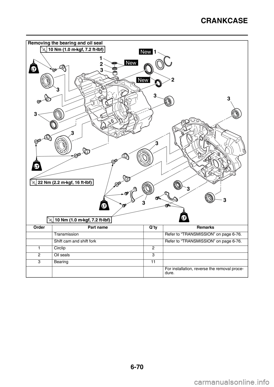
Removing the bearing and oil seal
Order Part name Q’ty Remarks
Transmission Refer to “TRANSMISSION” on page 6-76.
Shift cam and shift fork Refer to “TRANSMISSION” on page 6-76.
1 Circlip 2
2Oil seals 3
3 Bearing 11
For installation, reverse the removal proce-
dure.
LT
LT
LT
2
3
33
3
3
3 3
33
New
1
1
2
3
New
New
LT
22 Nm (2.2 mkgf, 16 ftIbf)T.R.
Page 300 of 428
CRANKCASE
6-71
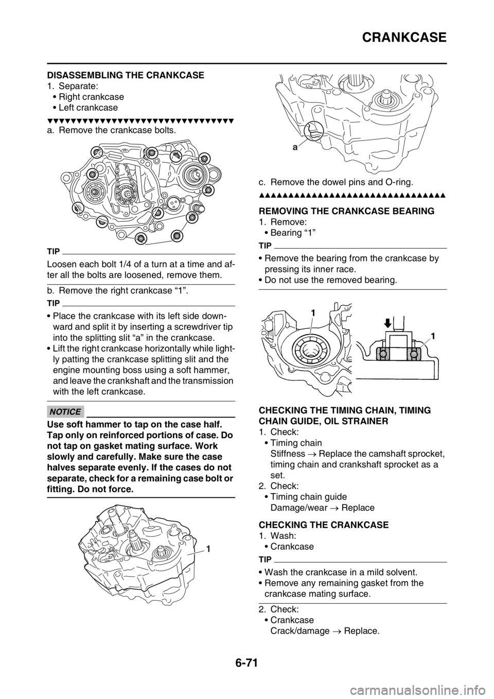
EAS2GB7311DISASSEMBLING THE CRANKCASE
1. Separate:
• Right crankcase
• Left crankcase
▼▼▼▼▼▼▼▼▼▼▼▼▼▼▼▼▼▼▼▼▼▼▼▼▼▼▼▼▼▼▼▼
a. Remove the crankcase bolts.
TIP
Loosen each bolt 1/4 of a turn at a time and af-
ter all the bolts are loosened, remove them.
b. Remove the right crankcase “1”.
TIP
• Place the crankcase with its left side down-
ward and split it by inserting a screwdriver tip
into the splitting slit “a” in the crankcase.
• Lift the right crankcase horizontally while light-
ly patting the crankcase splitting slit and the
engine mounting boss using a soft hammer,
and leave the crankshaft and the transmission
with the left crankcase.
ECA
NOTICE
Use soft hammer to tap on the case half.
Tap only on reinforced portions of case. Do
not tap on gasket mating surface. Work
slowly and carefully. Make sure the case
halves separate evenly. If the cases do not
separate, check for a remaining case bolt or
fitting. Do not force.c. Remove the dowel pins and O-ring.
▲▲▲▲▲▲▲▲▲▲▲▲▲▲▲▲▲▲▲▲▲▲▲▲▲▲▲▲▲▲▲▲
EAS2GB7312REMOVING THE CRANKCASE BEARING
1. Remove:
• Bearing “1”
TIP
• Remove the bearing from the crankcase by
pressing its inner race.
• Do not use the removed bearing.
EAS2GB7313CHECKING THE TIMING CHAIN, TIMING
CHAIN GUIDE, OIL STRAINER
1. Check:
• Timing chain
Stiffness Replace the camshaft sprocket,
timing chain and crankshaft sprocket as a
set.
2. Check:
• Timing chain guide
Damage/wear Replace
EAS2GB7314CHECKING THE CRANKCASE
1. Wash:
• Crankcase
TIP
• Wash the crankcase in a mild solvent.
• Remove any remaining gasket from the
crankcase mating surface.
2. Check:
• Crankcase
Crack/damage Replace.
1
a
Page 307 of 428
TRANSMISSION
6-78
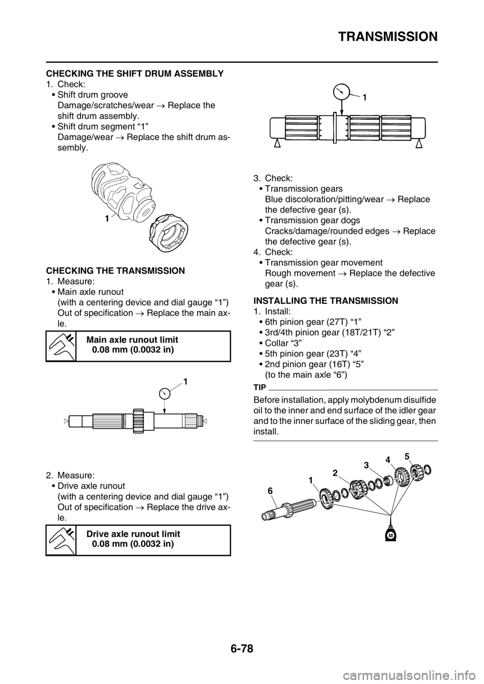
EAS2GB7325CHECKING THE SHIFT DRUM ASSEMBLY
1. Check:
• Shift drum groove
Damage/scratches/wear Replace the
shift drum assembly.
• Shift drum segment “1”
Damage/wear Replace the shift drum as-
sembly.
EAS2GB7326CHECKING THE TRANSMISSION
1. Measure:
• Main axle runout
(with a centering device and dial gauge “1”)
Out of specification Replace the main ax-
le.
2. Measure:
• Drive axle runout
(with a centering device and dial gauge “1”)
Out of specification Replace the drive ax-
le.3. Check:
• Transmission gears
Blue discoloration/pitting/wear Replace
the defective gear (s).
• Transmission gear dogs
Cracks/damage/rounded edges Replace
the defective gear (s).
4. Check:
• Transmission gear movement
Rough movement Replace the defective
gear (s).
EAS2GB7327INSTALLING THE TRANSMISSION
1. Install:
• 6th pinion gear (27T) “1”
• 3rd/4th pinion gear (18T/21T) “2”
• Collar “3”
• 5th pinion gear (23T) “4”
• 2nd pinion gear (16T) “5”
(to the main axle “6”)
TIP
Before installation, apply molybdenum disulfide
oil to the inner and end surface of the idler gear
and to the inner surface of the sliding gear, then
install. Main axle runout limit
0.08 mm (0.0032 in)
Drive axle runout limit
0.08 mm (0.0032 in)
34
2
1
6
5
M
Page 308 of 428
TRANSMISSION
6-79
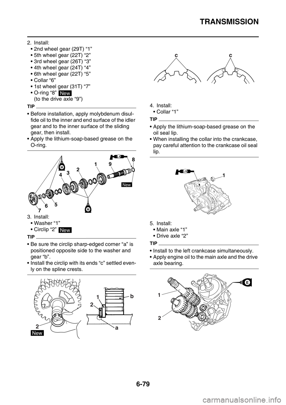
2. Install:
• 2nd wheel gear (29T) “1”
• 5th wheel gear (22T) “2”
• 3rd wheel gear (26T) “3”
• 4th wheel gear (24T) “4”
• 6th wheel gear (22T) “5”
• Collar “6”
• 1st wheel gear (31T) “7”
• O-ring “8”
(to the drive axle “9”)
TIP
• Before installation, apply molybdenum disul-
fide oil to the inner and end surface of the idler
gear and to the inner surface of the sliding
gear, then install.
• Apply the lithium-soap-based grease on the
O-ring.
3. Install:
• Washer “1”
• Circlip “2”
TIP
• Be sure the circlip sharp-edged corner “a” is
positioned opposite side to the washer and
gear “b”.
• Install the circlip with its ends “c” settled even-
ly on the spline crests.4. Install:
• Collar “1”
TIP
• Apply the lithium-soap-based grease on the
oil seal lip.
• When installing the collar into the crankcase,
pay careful attention to the crankcase oil seal
lip.
5. Install:
• Main axle “1”
• Drive axle “2”
TIP
• Install to the left crankcase simultaneously.
• Apply engine oil to the main axle and the drive
axle bearing.
New
891
234
567M
New
LS
M
New
21
2
ab
cc
1
2
EE
Page 309 of 428
TRANSMISSION
6-80
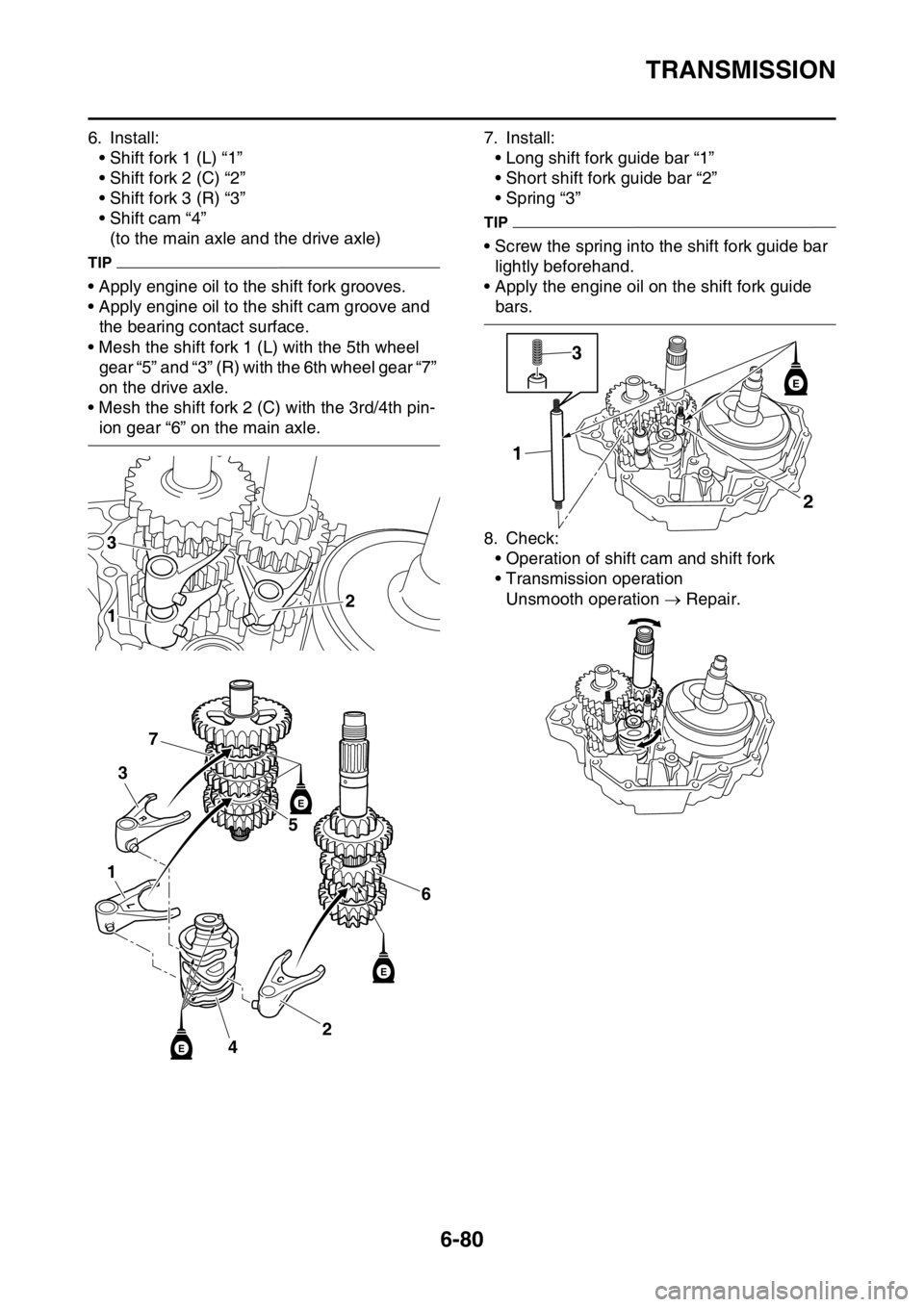
6. Install:
• Shift fork 1 (L) “1”
• Shift fork 2 (C) “2”
• Shift fork 3 (R) “3”
• Shift cam “4”
(to the main axle and the drive axle)
TIP
• Apply engine oil to the shift fork grooves.
• Apply engine oil to the shift cam groove and
the bearing contact surface.
• Mesh the shift fork 1 (L) with the 5th wheel
gear “5” and “3” (R) with the 6th wheel gear “7”
on the drive axle.
• Mesh the shift fork 2 (C) with the 3rd/4th pin-
ion gear “6” on the main axle.7. Install:
• Long shift fork guide bar “1”
• Short shift fork guide bar “2”
• Spring “3”
TIP
• Screw the spring into the shift fork guide bar
lightly beforehand.
• Apply the engine oil on the shift fork guide
bars.
8. Check:
• Operation of shift cam and shift fork
• Transmission operation
Unsmooth operation Repair.
3
12
6
2
4
5
3
7
1
E
E
E
2 13
E