clock YAMAHA WR 250F 2017 User Guide
[x] Cancel search | Manufacturer: YAMAHA, Model Year: 2017, Model line: WR 250F, Model: YAMAHA WR 250F 2017Pages: 432, PDF Size: 14.14 MB
Page 243 of 432
CAMSHAFT
6-14
EAS2GBB238REMOVING THE CAMSHAFT
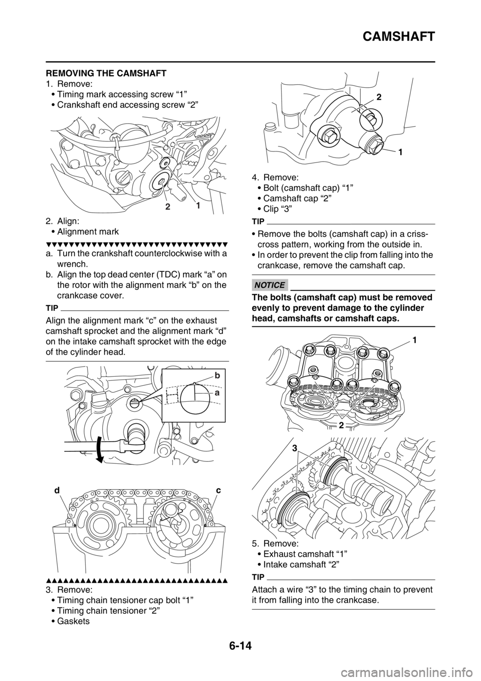
1. Remove:
• Timing mark accessing screw “1”
• Crankshaft end accessing screw “2”
2. Align:
• Alignment mark
▼▼▼▼▼▼▼▼▼▼▼▼▼▼▼▼▼▼▼▼▼▼▼▼▼▼▼▼▼▼▼▼
a. Turn the crankshaft counterclockwise with a
wrench.
b. Align the top dead center (TDC) mark “a” on
the rotor with the alignment mark “b” on the
crankcase cover.
TIP
Align the alignment mark “c” on the exhaust
camshaft sprocket and the alignment mark “d”
on the intake camshaft sprocket with the edge
of the cylinder head.
▲▲▲▲▲▲▲▲▲▲▲▲▲▲▲▲▲▲▲▲▲▲▲▲▲▲▲▲▲▲▲▲
3. Remove:
• Timing chain tensioner cap bolt “1”
• Timing chain tensioner “2”
•Gaskets4. Remove:
• Bolt (camshaft cap) “1”
• Camshaft cap “2”
• Clip “3”
TIP
• Remove the bolts (camshaft cap) in a criss-
cross pattern, working from the outside in.
• In order to prevent the clip from falling into the
crankcase, remove the camshaft cap.
ECA
NOTICE
The bolts (camshaft cap) must be removed
evenly to prevent damage to the cylinder
head, camshafts or camshaft caps.
5. Remove:
• Exhaust camshaft “1”
• Intake camshaft “2”
TIP
Attach a wire “3” to the timing chain to prevent
it from falling into the crankcase.
12
ab
dc
1 2
1
2
3
Page 245 of 432
CAMSHAFT
6-16
c. Install the dowel pins and the camshaft
caps.
TIP
• Tighten the camshaft cap bolts in a crisscross
pattern from innermost to outer caps.
• Do not turn the camshaft when measuring the
camshaft journal-to-camshaft cap clearance.
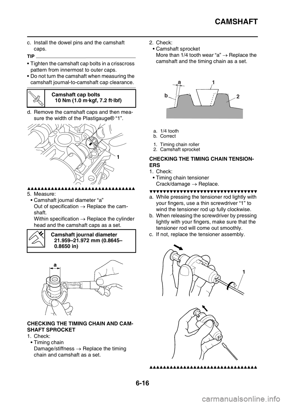
d. Remove the camshaft caps and then mea-
sure the width of the Plastigauge® “1”.
▲▲▲▲▲▲▲▲▲▲▲▲▲▲▲▲▲▲▲▲▲▲▲▲▲▲▲▲▲▲▲▲
5. Measure:
• Camshaft journal diameter “a”
Out of specification Replace the cam-
shaft.
Within specification Replace the cylinder
head and the camshaft caps as a set.
EAS2GBB240CHECKING THE TIMING CHAIN AND CAM-
SHAFT SPROCKET
1. Check:
•Timing chain
Damage/stiffness Replace the timing
chain and camshaft as a set.2. Check:
• Camshaft sprocket
More than 1/4 tooth wear “a” Replace the
camshaft and the timing chain as a set.
EAS2GBB241CHECKING THE TIMING CHAIN TENSION-
ERS
1. Check:
• Timing chain tensioner
Crack/damage Replace.
▼▼▼▼▼▼▼▼▼▼▼▼▼▼▼▼▼▼▼▼▼▼▼▼▼▼▼▼▼▼▼▼
a. While pressing the tensioner rod lightly with
your fingers, use a thin screwdriver “1” to
wind the tensioner rod up fully clockwise.
b. When releasing the screwdriver by pressing
lightly with your fingers, make sure that the
tensioner rod will come out smoothly.
c. If not, replace the tensioner assembly.
▲▲▲▲▲▲▲▲▲▲▲▲▲▲▲▲▲▲▲▲▲▲▲▲▲▲▲▲▲▲▲▲
Camshaft cap bolts
10 Nm (1.0 m·kgf, 7.2 ft·lbf)
Camshaft journal diameter
21.959–21.972 mm (0.8645–
0.8650 in)
T R..
1
a. 1/4 tooth
b. Correct
1. Timing chain roller
2. Camshaft sprocket
a
b1
2
Page 246 of 432
CAMSHAFT
6-17
EAS2GBB242CHECKING THE DECOMPRESSION SYS-
TEM
1. Check:
• Decompression system
▼▼▼▼▼▼▼▼▼▼▼▼▼▼▼▼▼▼▼▼▼▼▼▼▼▼▼▼▼▼▼▼
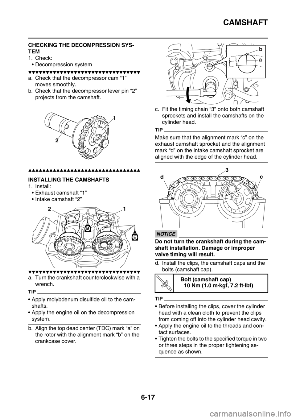
a. Check that the decompressor cam “1”
moves smoothly.
b. Check that the decompressor lever pin “2”
projects from the camshaft.
▲▲▲▲▲▲▲▲▲▲▲▲▲▲▲▲▲▲▲▲▲▲▲▲▲▲▲▲▲▲▲▲
EAS2GBB243INSTALLING THE CAMSHAFTS
1. Install:
• Exhaust camshaft “1”
• Intake camshaft “2”
▼▼▼▼▼▼▼▼▼▼▼▼▼▼▼▼▼▼▼▼▼▼▼▼▼▼▼▼▼▼▼▼
a. Turn the crankshaft counterclockwise with a
wrench.
TIP
• Apply molybdenum disulfide oil to the cam-
shafts.
• Apply the engine oil on the decompression
system.
b. Align the top dead center (TDC) mark “a” on
the rotor with the alignment mark “b” on the
crankcase cover.c. Fit the timing chain “3” onto both camshaft
sprockets and install the camshafts on the
cylinder head.
TIP
Make sure that the alignment mark “c” on the
exhaust camshaft sprocket and the alignment
mark “d” on the intake camshaft sprocket are
aligned with the edge of the cylinder head.
ECA33DD029
NOTICE
Do not turn the crankshaft during the cam-
shaft installation. Damage or improper
valve timing will result.
d. Install the clips, the camshaft caps and the
bolts (camshaft cap).
TIP
• Before installing the clips, cover the cylinder
head with a clean cloth to prevent the clips
from coming off into the cylinder head cavity.
• Apply the engine oil to the threads and con-
tact surfaces.
• Tighten the bolts to the specified torque in two
or three steps in the proper tightening se-
quence as shown.
1
2
Bolt (camshaft cap)
10 Nm (1.0 m·kgf, 7.2 ft·lbf)
ab
dc
3
T R..
Page 247 of 432
CAMSHAFT
6-18
ECA33DD030
NOTICE
The bolts (camshaft cap) must be tightened
evenly, or damage to the cylinder head,
camshaft caps, and camshaft will result.
▲▲▲▲▲▲▲▲▲▲▲▲▲▲▲▲▲▲▲▲▲▲▲▲▲▲▲▲▲▲▲▲
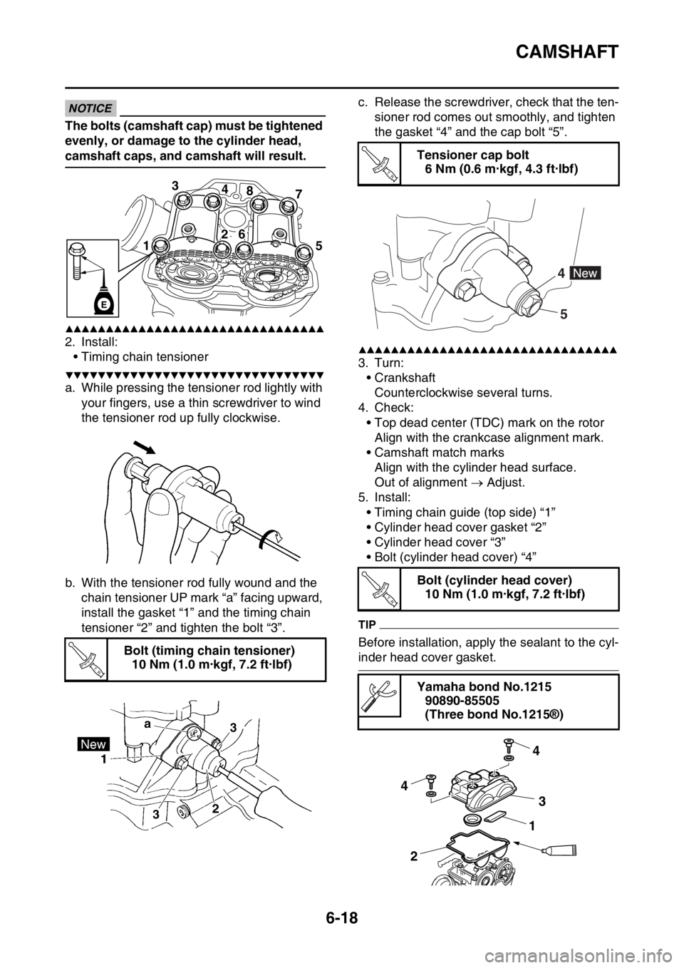
2. Install:
• Timing chain tensioner
▼▼▼▼▼▼▼▼▼▼▼▼▼▼▼▼▼▼▼▼▼▼▼▼▼▼▼▼▼▼▼▼
a. While pressing the tensioner rod lightly with
your fingers, use a thin screwdriver to wind
the tensioner rod up fully clockwise.
b. With the tensioner rod fully wound and the
chain tensioner UP mark “a” facing upward,
install the gasket “1” and the timing chain
tensioner “2” and tighten the bolt “3”.c. Release the screwdriver, check that the ten-
sioner rod comes out smoothly, and tighten
the gasket “4” and the cap bolt “5”.
▲▲▲▲▲▲▲▲▲▲▲▲▲▲▲▲▲▲▲▲▲▲▲▲▲▲▲▲▲▲▲▲
3. Turn:
• Crankshaft
Counterclockwise several turns.
4. Check:
• Top dead center (TDC) mark on the rotor
Align with the crankcase alignment mark.
• Camshaft match marks
Align with the cylinder head surface.
Out of alignment Adjust.
5. Install:
• Timing chain guide (top side) “1”
• Cylinder head cover gasket “2”
• Cylinder head cover “3”
• Bolt (cylinder head cover) “4”
TIP
Before installation, apply the sealant to the cyl-
inder head cover gasket. Bolt (timing chain tensioner)
10 Nm (1.0 m·kgf, 7.2 ft·lbf)
3
4
8
7
15
26
E
T R..
Tensioner cap bolt
6 Nm (0.6 m·kgf, 4.3 ft·lbf)
Bolt (cylinder head cover)
10 Nm (1.0 m·kgf, 7.2 ft·lbf)
Yamaha bond No.1215
90890-85505
(Three bond No.1215®)
T R..
4
5
T R..
4
4
3
21
Page 282 of 432
KICKSTATER
6-53
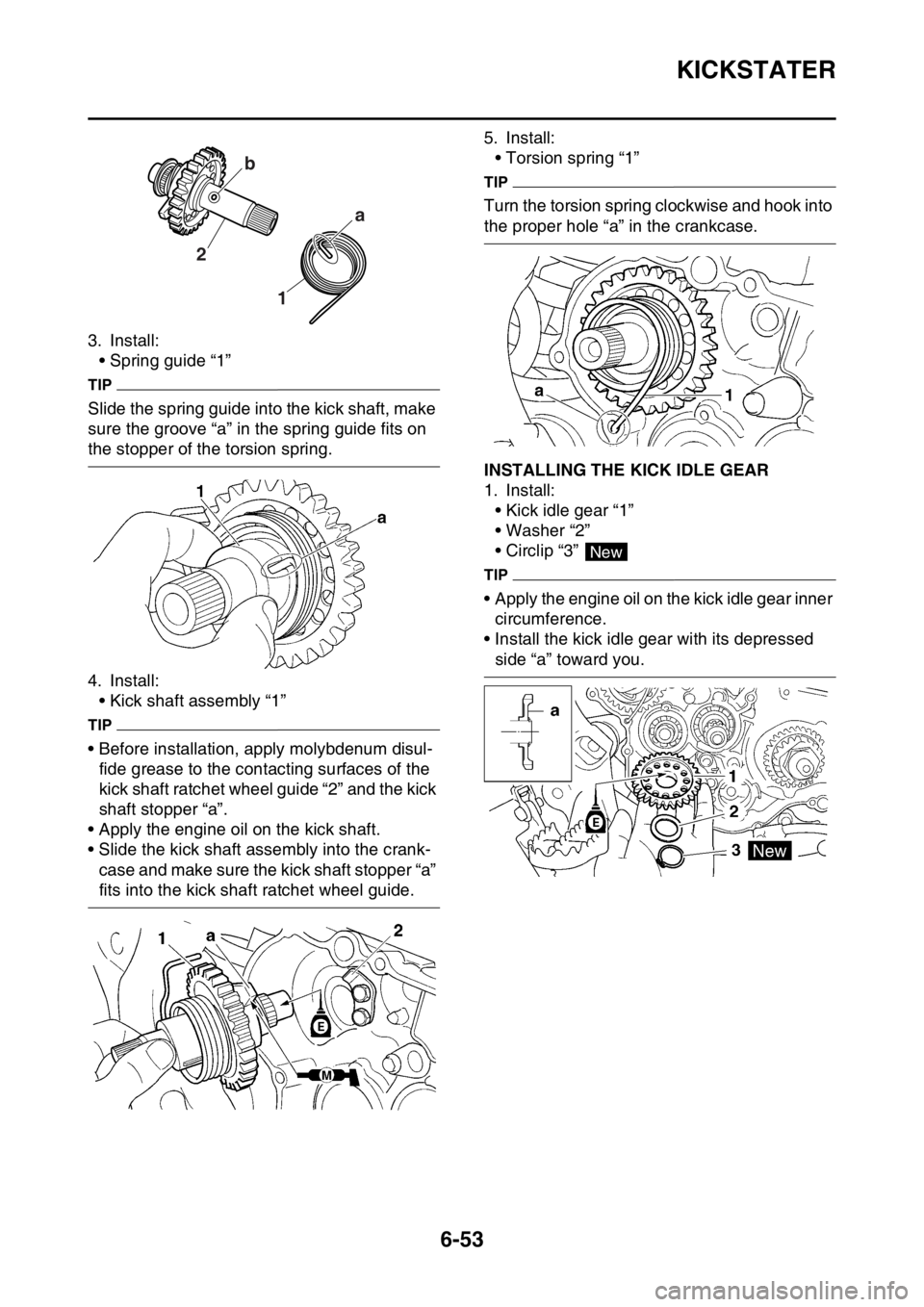
3. Install:
• Spring guide “1”
TIP
Slide the spring guide into the kick shaft, make
sure the groove “a” in the spring guide fits on
the stopper of the torsion spring.
4. Install:
• Kick shaft assembly “1”
TIP
• Before installation, apply molybdenum disul-
fide grease to the contacting surfaces of the
kick shaft ratchet wheel guide “2” and the kick
shaft stopper “a”.
• Apply the engine oil on the kick shaft.
• Slide the kick shaft assembly into the crank-
case and make sure the kick shaft stopper “a”
fits into the kick shaft ratchet wheel guide.5. Install:
• Torsion spring “1”
TIP
Turn the torsion spring clockwise and hook into
the proper hole “a” in the crankcase.
EAS2GBB286INSTALLING THE KICK IDLE GEAR
1. Install:
• Kick idle gear “1”
• Washer “2”
• Circlip “3”
TIP
• Apply the engine oil on the kick idle gear inner
circumference.
• Install the kick idle gear with its depressed
side “a” toward you.
1 2a b
New
Page 285 of 432
SHIFT SHAFT
6-56
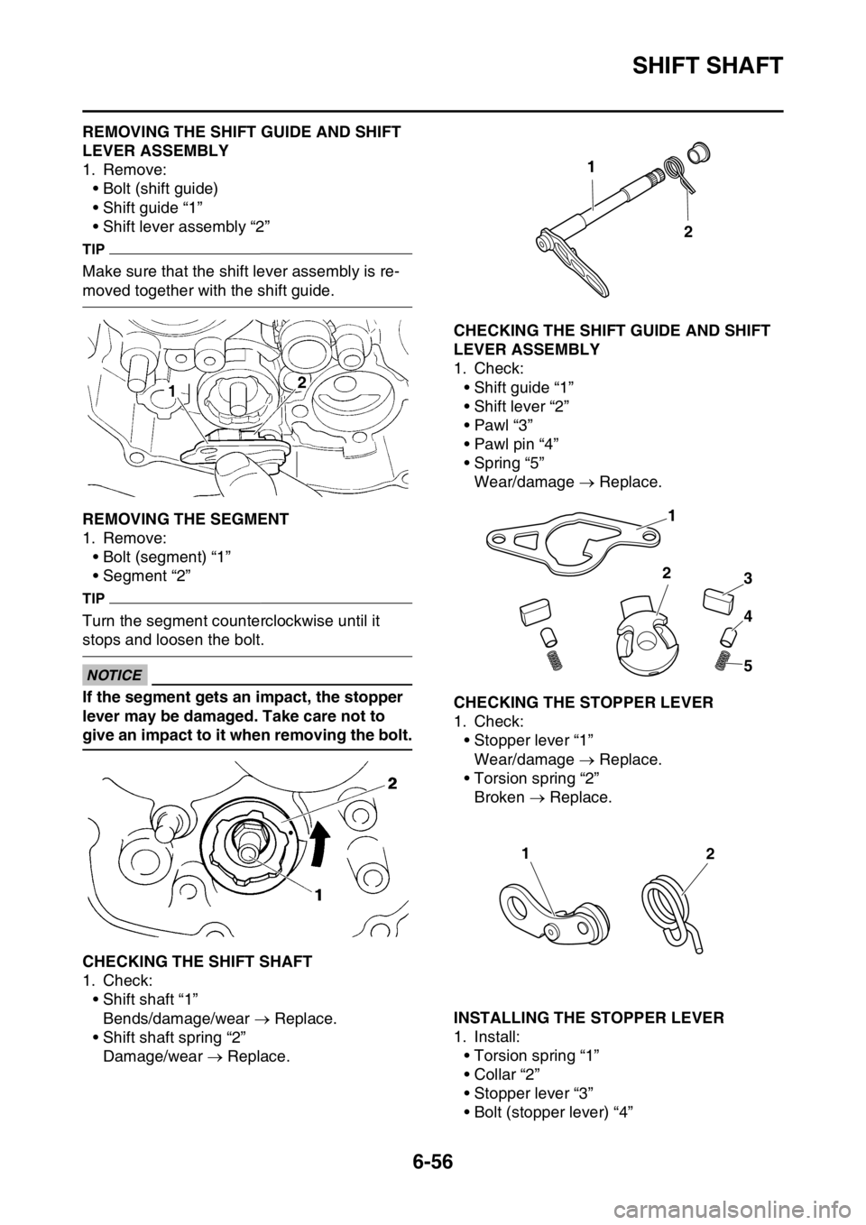
EAS2GBB288REMOVING THE SHIFT GUIDE AND SHIFT
LEVER ASSEMBLY
1. Remove:
• Bolt (shift guide)
• Shift guide “1”
• Shift lever assembly “2”
TIP
Make sure that the shift lever assembly is re-
moved together with the shift guide.
EAS2GBB289REMOVING THE SEGMENT
1. Remove:
• Bolt (segment) “1”
• Segment “2”
TIP
Turn the segment counterclockwise until it
stops and loosen the bolt.
ECA
NOTICE
If the segment gets an impact, the stopper
lever may be damaged. Take care not to
give an impact to it when removing the bolt.
EAS2GBB290CHECKING THE SHIFT SHAFT
1. Check:
• Shift shaft “1”
Bends/damage/wear Replace.
• Shift shaft spring “2”
Damage/wear Replace.
EAS2GBB291CHECKING THE SHIFT GUIDE AND SHIFT
LEVER ASSEMBLY
1. Check:
• Shift guide “1”
• Shift lever “2”
•Pawl “3”
• Pawl pin “4”
• Spring “5”
Wear/damage Replace.
EAS2GBB292CHECKING THE STOPPER LEVER
1. Check:
• Stopper lever “1”
Wear/damage Replace.
• Torsion spring “2”
Broken Replace.
EAS2GBB293INSTALLING THE STOPPER LEVER
1. Install:
• Torsion spring “1”
• Collar “2”
• Stopper lever “3”
• Bolt (stopper lever) “4”
1
2
1
2
3
4
5
12
Page 297 of 432
GENERATOR AND STARTER CLUTCH
6-68
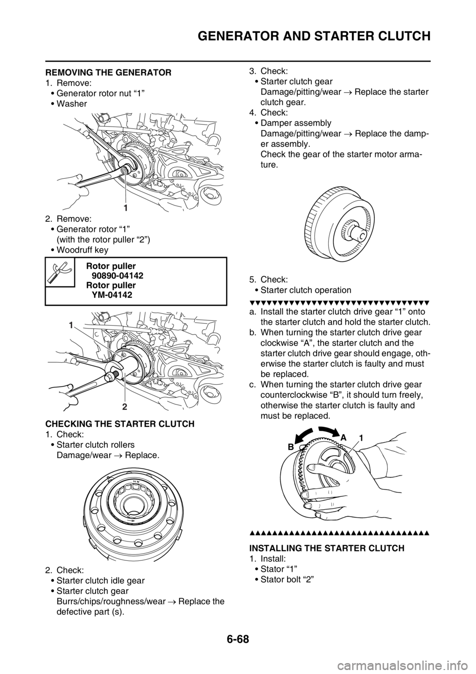
EAS2GBB306REMOVING THE GENERATOR
1. Remove:
• Generator rotor nut “1”
• Washer
2. Remove:
• Generator rotor “1”
(with the rotor puller “2”)
• Woodruff key
EAS2GBB307CHECKING THE STARTER CLUTCH
1. Check:
• Starter clutch rollers
Damage/wear Replace.
2. Check:
• Starter clutch idle gear
• Starter clutch gear
Burrs/chips/roughness/wear Replace the
defective part (s).3. Check:
• Starter clutch gear
Damage/pitting/wear Replace the starter
clutch gear.
4. Check:
• Damper assembly
Damage/pitting/wear Replace the damp-
er assembly.
Check the gear of the starter motor arma-
ture.
5. Check:
• Starter clutch operation
▼▼▼▼▼▼▼▼▼▼▼▼▼▼▼▼▼▼▼▼▼▼▼▼▼▼▼▼▼▼▼▼
a. Install the starter clutch drive gear “1” onto
the starter clutch and hold the starter clutch.
b. When turning the starter clutch drive gear
clockwise “A”, the starter clutch and the
starter clutch drive gear should engage, oth-
erwise the starter clutch is faulty and must
be replaced.
c. When turning the starter clutch drive gear
counterclockwise “B”, it should turn freely,
otherwise the starter clutch is faulty and
must be replaced.
▲▲▲▲▲▲▲▲▲▲▲▲▲▲▲▲▲▲▲▲▲▲▲▲▲▲▲▲▲▲▲▲
EAS2GBB308INSTALLING THE STARTER CLUTCH
1. Install:
• Stator “1”
• Stator bolt “2” Rotor puller
90890-04142
Rotor puller
YM-04142
1
1
2
1 A
B
Page 403 of 432
ELECTRICAL COMPONENTS
9-67
EAS27990CHECKING THE BULBS AND BULB SOCK-
ETS
TIP
Do not check any of the lights that use LEDs.
Check each bulb and bulb socket for damage
or wear, proper connections, and also for con-
tinuity between the terminals.
Damage/wear Repair or replace the bulb,
bulb socket or both.
Improperly connected Properly connect.
No continuity Repair or replace the bulb,
bulb socket or both.
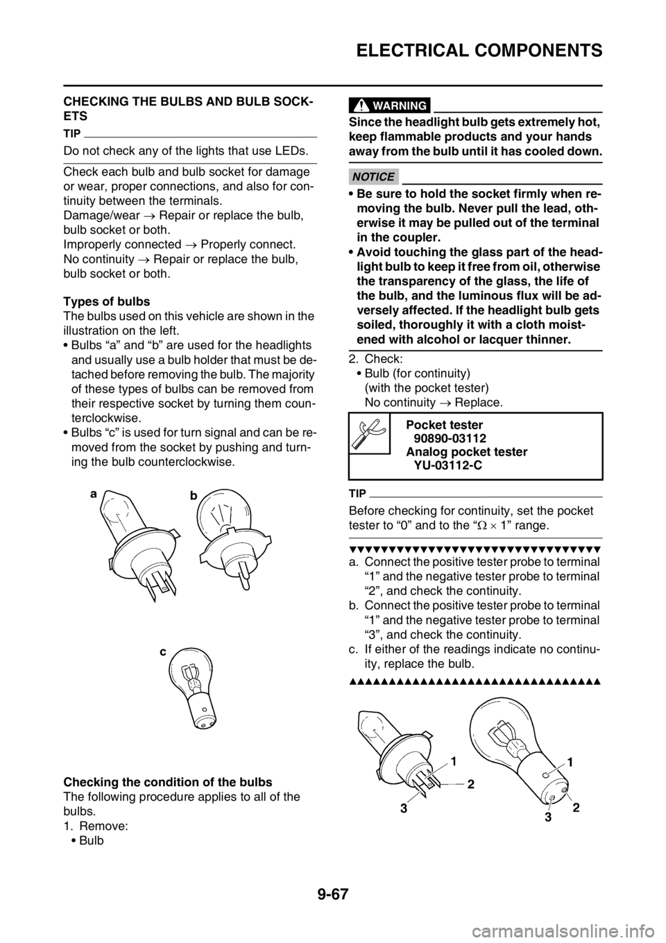
Types of bulbs
The bulbs used on this vehicle are shown in the
illustration on the left.
• Bulbs “a” and “b” are used for the headlights
and usually use a bulb holder that must be de-
tached before removing the bulb. The majority
of these types of bulbs can be removed from
their respective socket by turning them coun-
terclockwise.
• Bulbs “c” is used for turn signal and can be re-
moved from the socket by pushing and turn-
ing the bulb counterclockwise.
Checking the condition of the bulbs
The following procedure applies to all of the
bulbs.
1. Remove:
•Bulb
EWA
WARNING
Since the headlight bulb gets extremely hot,
keep flammable products and your hands
away from the bulb until it has cooled down.
ECA
NOTICE
• Be sure to hold the socket firmly when re-
moving the bulb. Never pull the lead, oth-
erwise it may be pulled out of the terminal
in the coupler.
• Avoid touching the glass part of the head-
light bulb to keep it free from oil, otherwise
the transparency of the glass, the life of
the bulb, and the luminous flux will be ad-
versely affected. If the headlight bulb gets
soiled, thoroughly it with a cloth moist-
ened with alcohol or lacquer thinner.
2. Check:
• Bulb (for continuity)
(with the pocket tester)
No continuity Replace.
TIP
Before checking for continuity, set the pocket
tester to “0” and to the “ 1” range.
▼▼▼▼▼▼▼▼▼▼▼▼▼▼▼▼▼▼▼▼▼▼▼▼▼▼▼▼▼▼▼▼
a. Connect the positive tester probe to terminal
“1” and the negative tester probe to terminal
“2”, and check the continuity.
b. Connect the positive tester probe to terminal
“1” and the negative tester probe to terminal
“3”, and check the continuity.
c. If either of the readings indicate no continu-
ity, replace the bulb.
▲▲▲▲▲▲▲▲▲▲▲▲▲▲▲▲▲▲▲▲▲▲▲▲▲▲▲▲▲▲▲▲
Pocket tester
90890-03112
Analog pocket tester
YU-03112-C