drain bolt YAMAHA WR 250F 2017 User Guide
[x] Cancel search | Manufacturer: YAMAHA, Model Year: 2017, Model line: WR 250F, Model: YAMAHA WR 250F 2017Pages: 432, PDF Size: 14.14 MB
Page 167 of 432
FRONT BRAKE
5-13
EAS2GBB167
FRONT BRAKE
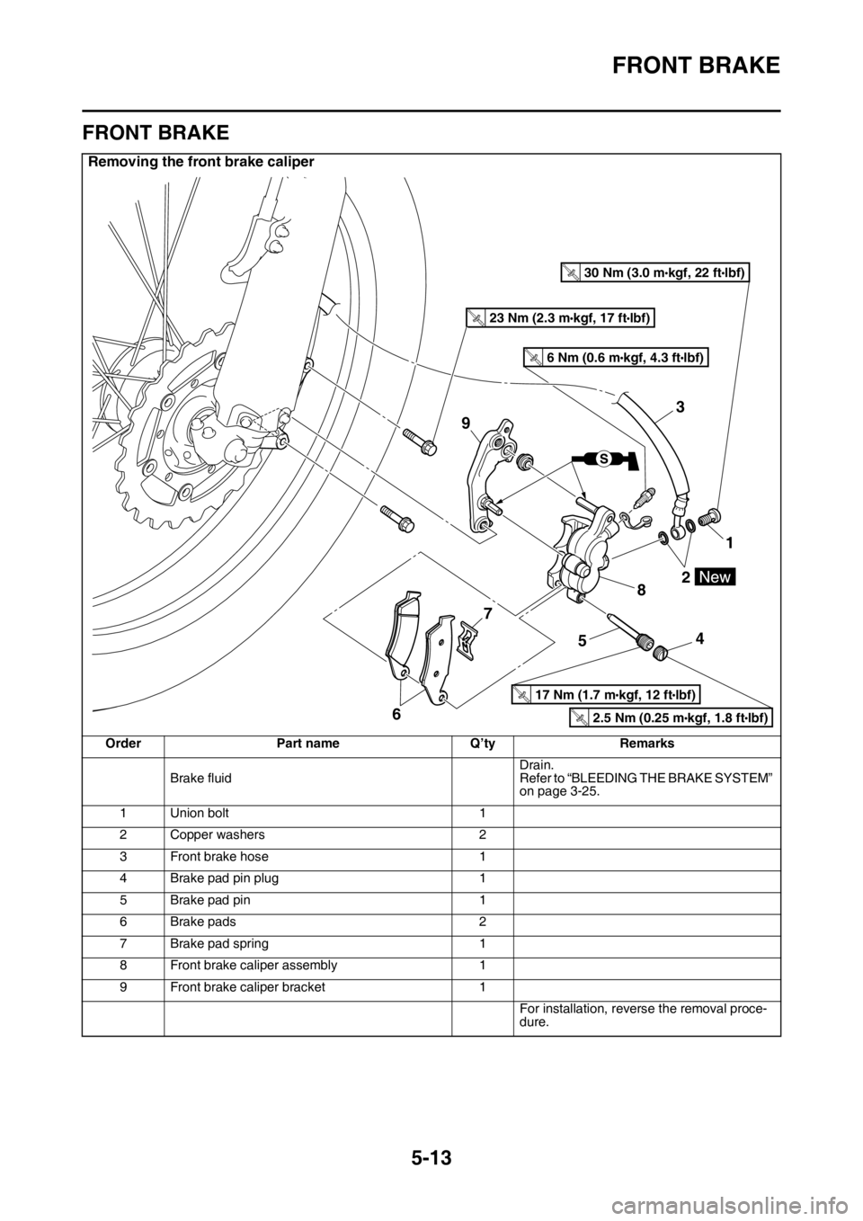
Removing the front brake caliper
Order Part name Q’ty Remarks
Brake fluidDrain.
Refer to “BLEEDING THE BRAKE SYSTEM”
on page 3-25.
1 Union bolt 1
2 Copper washers 2
3 Front brake hose 1
4 Brake pad pin plug 1
5 Brake pad pin 1
6 Brake pads 2
7 Brake pad spring 1
8 Front brake caliper assembly 1
9 Front brake caliper bracket 1
For installation, reverse the removal proce-
dure.
3
9
1
2
8
4
5 7
6
T.R.30 Nm (3.0 mlbf) kgf, 22 ft
T.R.23 Nm (2.3 mlbf) kgf, 17 ft
T.R.17 Nm (1.7 mlbf) kgf, 12 ft
T.R.2.5 Nm (0.25 mlbf) kgf, 1.8 ft
T.R.6 Nm (0.6 mlbf) kgf, 4.3 ft
Page 169 of 432
FRONT BRAKE
5-15
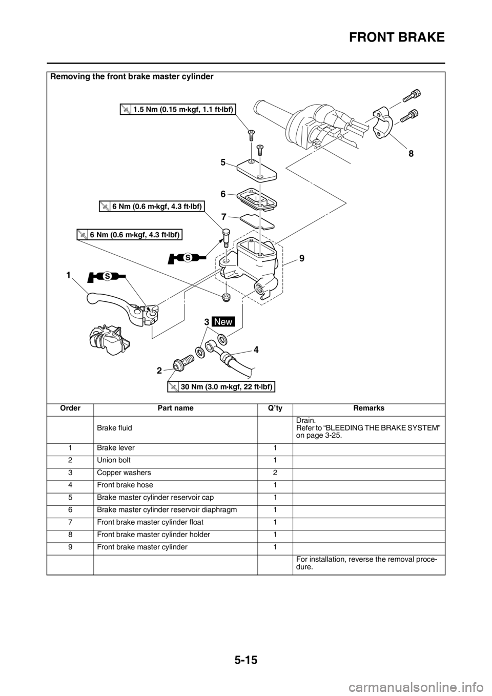
Removing the front brake master cylinder
Order Part name Q’ty Remarks
Brake fluidDrain.
Refer to “BLEEDING THE BRAKE SYSTEM”
on page 3-25.
1 Brake lever 1
2 Union bolt 1
3 Copper washers 2
4 Front brake hose 1
5 Brake master cylinder reservoir cap 1
6 Brake master cylinder reservoir diaphragm 1
7 Front brake master cylinder float 1
8 Front brake master cylinder holder 1
9 Front brake master cylinder 1
For installation, reverse the removal proce-
dure.
5
6
7
23
48
9
1
T.R.30 Nm (3.0 mlbf) kgf, 22 ft
T.R.1.5 Nm (0.15 mlbf) kgf, 1.1 ft
T.R.6 Nm (0.6 mlbf) kgf, 4.3 ft
T.R.6 Nm (0.6 mlbf) kgf, 4.3 ft
Page 171 of 432
FRONT BRAKE
5-17
EAS2GBB168INTRODUCTIONEWA
WARNING
If you need to disassemble the disc brake
components, observe the following precau-
tions.
• Never disassemble the brake components
unless absolutely necessary.
• If there is any problem with connections
on the hydraulic brake system, perform
the following jobs.
Disassemble the brake system, drain the
brake fluid, and clean it. After that, add a
suitable amount of brake fluid. Then, bleed
it after reassembly.
• Use only brake fluid for washing brake
components.
• Use new brake fluid for cleaning the brake
components.
• Immediately wipe off the spilled brake fluid
to avoid damage to painted surfaces or
plastic parts.
• Handle brake fluid with special care not to
let it enter your eyes so that you may not
lost your eyesight.
• FIRST AID FOR BRAKE FLUID ENTERING
THE EYES:
• Flush with water for 15 minutes and get
immediate medical attention.
EAS2GBB169CHECKING THE FRONT BRAKE DISC
1. Remove:
• Front wheel
Refer to “FRONT WHEEL” on page 5-4.
2. Check:
• Front brake disc
Damage/galling Replace.
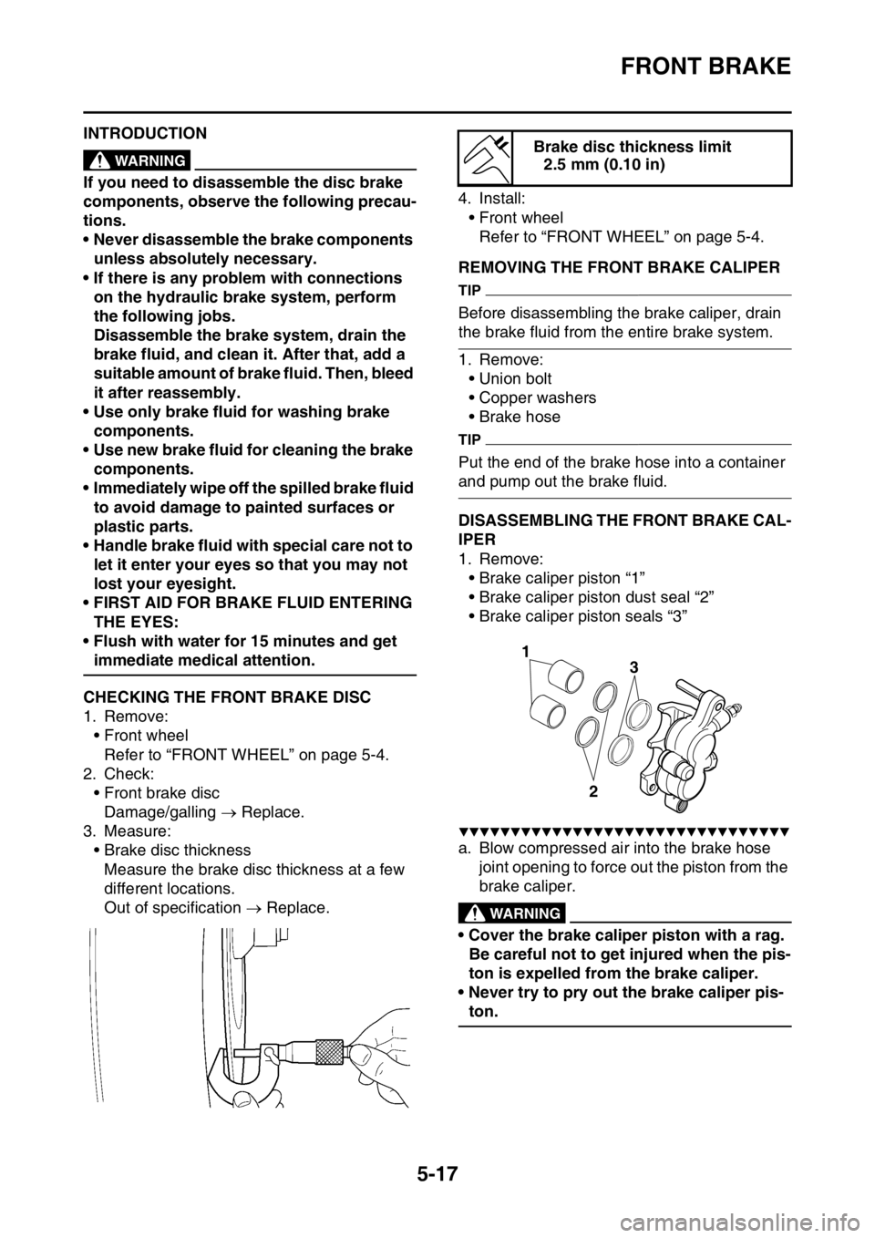
3. Measure:
• Brake disc thickness
Measure the brake disc thickness at a few
different locations.
Out of specification Replace.4. Install:
• Front wheel
Refer to “FRONT WHEEL” on page 5-4.
EAS2GBB170REMOVING THE FRONT BRAKE CALIPER
TIP
Before disassembling the brake caliper, drain
the brake fluid from the entire brake system.
1. Remove:
• Union bolt
• Copper washers
• Brake hose
TIP
Put the end of the brake hose into a container
and pump out the brake fluid.
EAS2GBB171DISASSEMBLING THE FRONT BRAKE CAL-
IPER
1. Remove:
• Brake caliper piston “1”
• Brake caliper piston dust seal “2”
• Brake caliper piston seals “3”
▼▼▼▼▼▼▼▼▼▼▼▼▼▼▼▼▼▼▼▼▼▼▼▼▼▼▼▼▼▼▼▼
a. Blow compressed air into the brake hose
joint opening to force out the piston from the
brake caliper.
EWA
WARNING
• Cover the brake caliper piston with a rag.
Be careful not to get injured when the pis-
ton is expelled from the brake caliper.
• Never try to pry out the brake caliper pis-
ton.
Brake disc thickness limit
2.5 mm (0.10 in)
3
2
1
Page 174 of 432
FRONT BRAKE
5-20
ECA
NOTICE
Brake fluid may damage painted surfaces
and plastic parts. Therefore, always clean
up any spilt brake fluid immediately.
5. Bleed:
• Brake system
Refer to “BLEEDING THE BRAKE SYS-
TEM” on page 3-25.
6. Check:
• Brake fluid level
The minimum level mark or below Add.
Refer to “CHECKING THE BRAKE FLUID
LEVEL” on page 3-30.
7. Check:
• Brake lever free play
Refer to “ADJUSTING THE FRONT
BRAKE” on page 3-26.
• Brake lever operation
A softy or spongy feeling Bleed the brake
system.
Refer to “BLEEDING THE BRAKE SYS-
TEM” on page 3-25.
EAS2GBB176REMOVING THE FRONT BRAKE MASTER
CYLINDER
TIP
Before removing the front brake master cylin-
der, drain the brake fluid from the entire brake
system.
1. Remove:
• Union bolt
• Copper washers
• Brake hoses
TIP
To drain any remaining brake fluid, place a con-
tainer under the master cylinder and the end of
the brake hose.
EAS2GBB177CHECKING THE FRONT BRAKE MASTER
CYLINDER
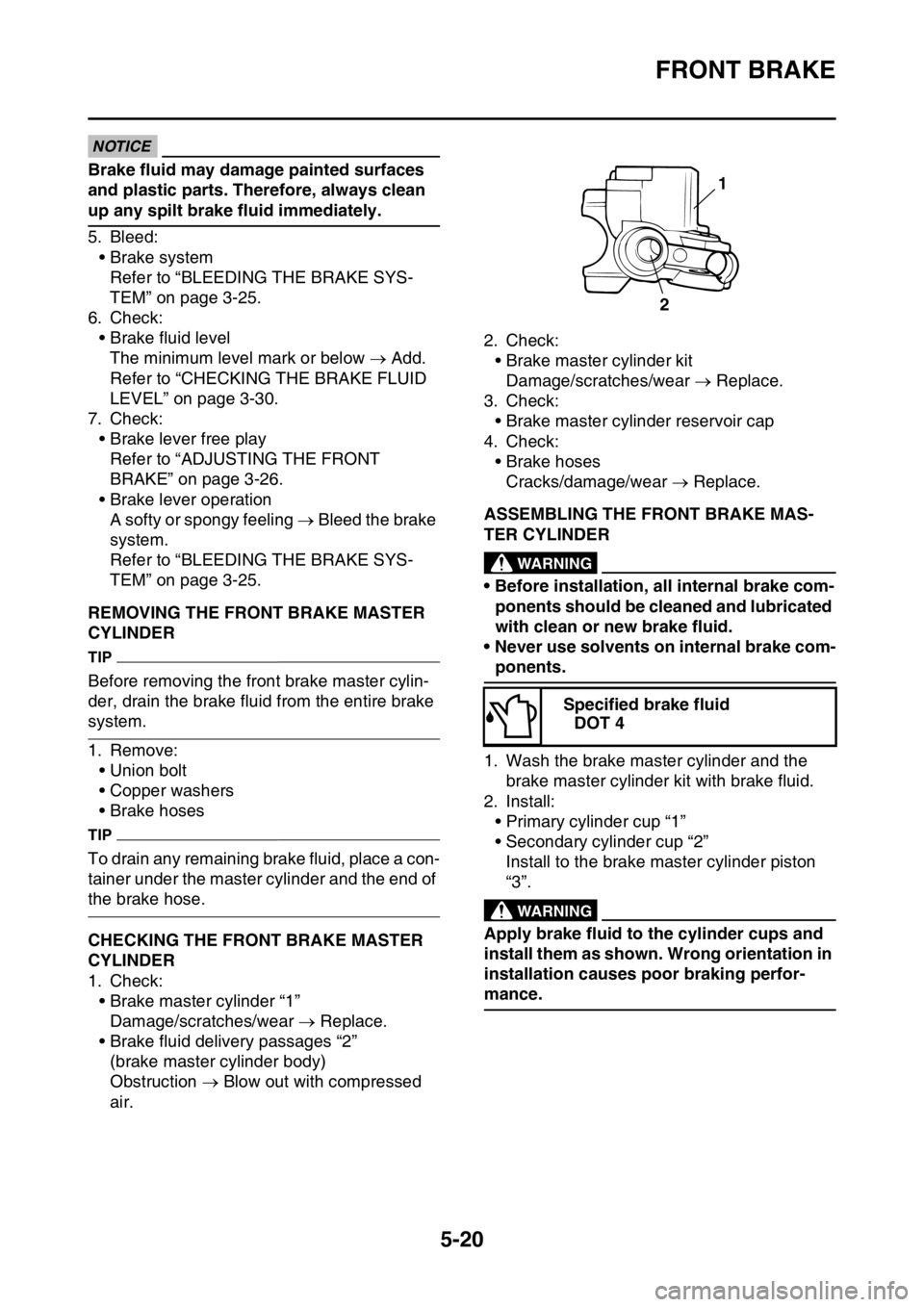
1. Check:
• Brake master cylinder “1”
Damage/scratches/wear Replace.
• Brake fluid delivery passages “2”
(brake master cylinder body)
Obstruction Blow out with compressed
air.2. Check:
• Brake master cylinder kit
Damage/scratches/wear Replace.
3. Check:
• Brake master cylinder reservoir cap
4. Check:
• Brake hoses
Cracks/damage/wear Replace.
EAS2GBB178ASSEMBLING THE FRONT BRAKE MAS-
TER CYLINDER
EWA
WARNING
• Before installation, all internal brake com-
ponents should be cleaned and lubricated
with clean or new brake fluid.
• Never use solvents on internal brake com-
ponents.
1. Wash the brake master cylinder and the
brake master cylinder kit with brake fluid.
2. Install:
• Primary cylinder cup “1”
• Secondary cylinder cup “2”
Install to the brake master cylinder piston
“3”.
EWA
WARNING
Apply brake fluid to the cylinder cups and
install them as shown. Wrong orientation in
installation causes poor braking perfor-
mance.Specified brake fluid
DOT 4
1
2
Page 177 of 432
REAR BRAKE
5-23
EAS2GBB180
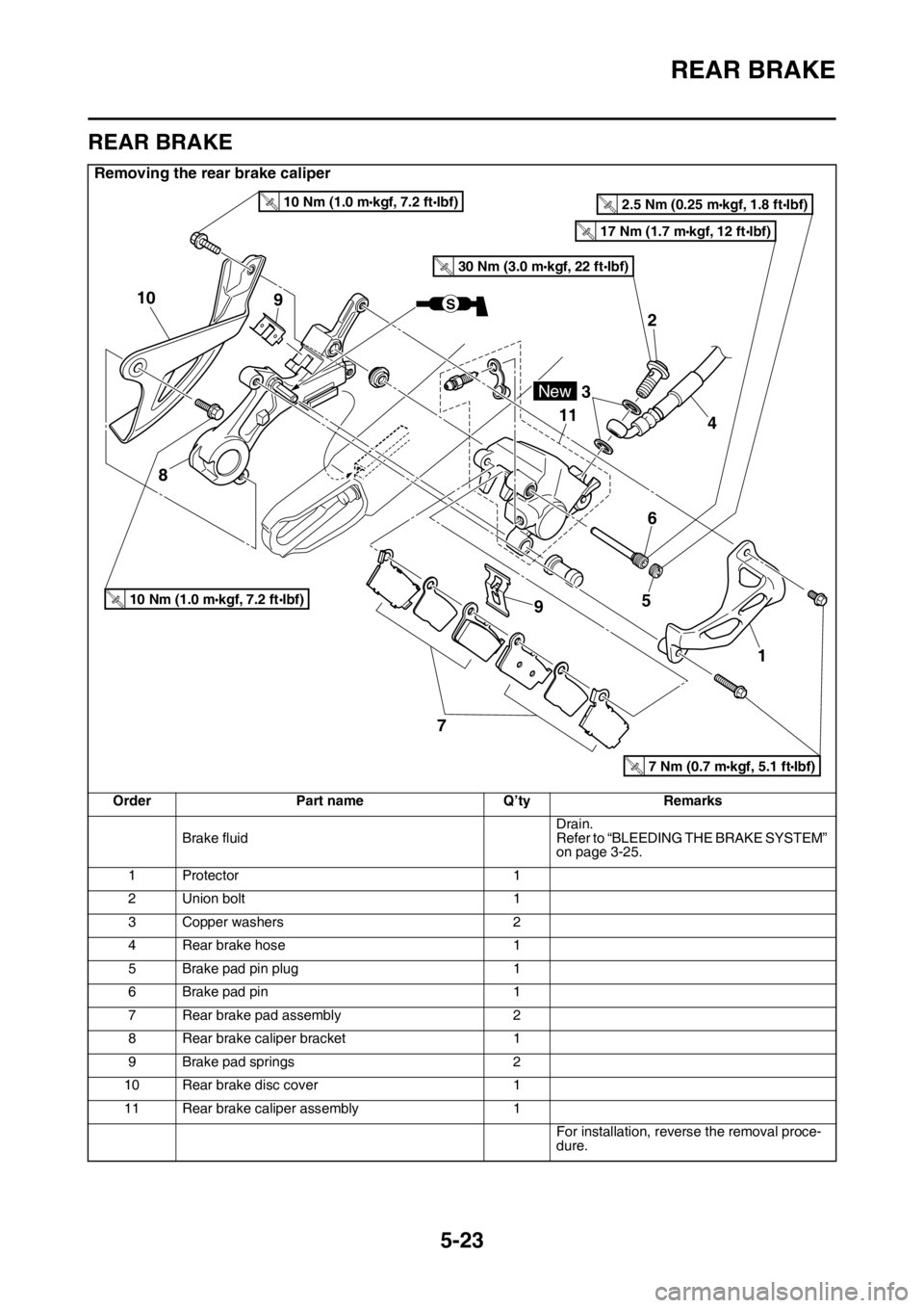
REAR BRAKE
Removing the rear brake caliper
Order Part name Q’ty Remarks
Brake fluidDrain.
Refer to “BLEEDING THE BRAKE SYSTEM”
on page 3-25.
1 Protector 1
2 Union bolt 1
3 Copper washers 2
4 Rear brake hose 1
5 Brake pad pin plug 1
6 Brake pad pin 1
7 Rear brake pad assembly 2
8 Rear brake caliper bracket 1
9 Brake pad springs 2
10 Rear brake disc cover 1
11 Rear brake caliper assembly 1
For installation, reverse the removal proce-
dure.
2
3
4 11
56
79
1
8
9 10
2.5 Nm (0.25 m•kgf, 1.8 ft•Ibf)T.R.
10 Nm (1.0 m•kgf, 7.2 ft•Ibf)T.R.
10 Nm (1.0 m•kgf, 7.2 ft•Ibf)T.R.
17 Nm (1.7 m•kgf, 12 ft•Ibf)T.R.
30 Nm (3.0 m•kgf, 22 ft•Ibf)T.R.
New
S
7 Nm (0.7 m•kgf, 5.1 ft•Ibf)T.R.
Page 179 of 432
REAR BRAKE
5-25
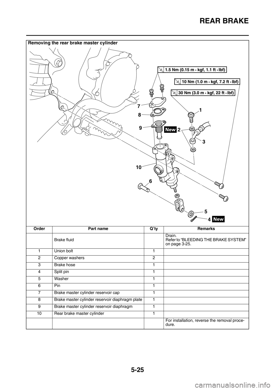
Removing the rear brake master cylinder
Order Part name Q’ty Remarks
Brake fluidDrain.
Refer to “BLEEDING THE BRAKE SYSTEM”
on page 3-25.
1 Union bolt 1
2 Copper washers 2
3 Brake hose 1
4 Split pin 1
5Washer 1
6Pin 1
7 Brake master cylinder reservoir cap 1
8 Brake master cylinder reservoir diaphragm plate 1
9 Brake master cylinder reservoir diaphragm 1
10 Rear brake master cylinder 1
For installation, reverse the removal proce-
dure.
1
2
3
4 7
5 8
6 9
T R..
T R..
10
T R..
Page 181 of 432
REAR BRAKE
5-27
EAS2GBB181INTRODUCTIONEWA
WARNING
If you need to disassemble the disc brake
components, observe the following precau-
tions.
• Never disassemble the brake components
unless absolutely necessary.
• If there is any problem with connections
on the hydraulic brake system, perform
the following jobs.
Disassemble the brake system, drain the
brake fluid, and clean it. After that, add a
suitable amount of brake fluid. Then, bleed
it after reassembly.
• Use only brake fluid for washing internal
brake components.
• Use new brake fluid for cleaning the brake
components.
• Immediately wipe off the spilled brake fluid
to avoid damage to painted surfaces or
plastic parts.
• Handle brake fluid with special care not to
let it enter your eyes so that you may not
lost your eyesight.
• FIRST AID FOR BRAKE FLUID ENTERING
THE EYES:
• Flush with water for 15 minutes and get
immediate medical attention.
EAS2GBB182CHECKING THE REAR BRAKE DISC
1. Remove:
• Rear wheel
Refer to “REAR WHEEL” on page 5-9.
2. Check:
• Brake disc
Damage/galling Replace.
3. Measure:
• Brake disc thickness
Measure the brake disc thickness at a few
different locations.
Out of specification Replace.
Refer to “CHECKING THE FRONT BRAKE
DISC” on page 5-17.
4. Measure:
• Brake disc deflection
Out of specification Correct the brake disc
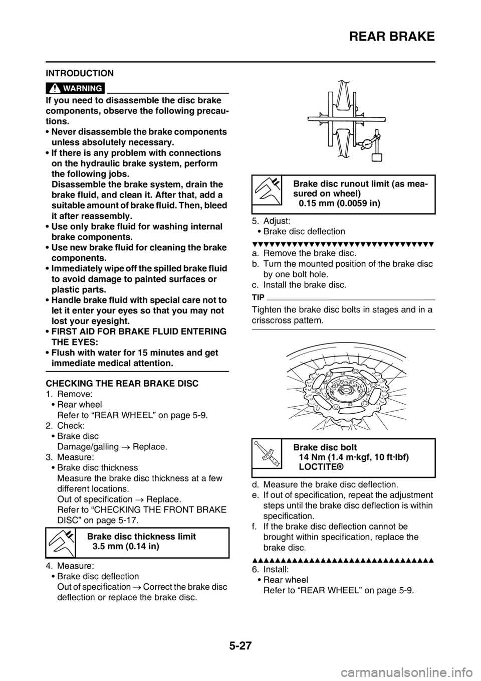
deflection or replace the brake disc.5. Adjust:
• Brake disc deflection
▼▼▼▼▼▼▼▼▼▼▼▼▼▼▼▼▼▼▼▼▼▼▼▼▼▼▼▼▼▼▼▼
a. Remove the brake disc.
b. Turn the mounted position of the brake disc
by one bolt hole.
c. Install the brake disc.
TIP
Tighten the brake disc bolts in stages and in a
crisscross pattern.
d. Measure the brake disc deflection.
e. If out of specification, repeat the adjustment
steps until the brake disc deflection is within
specification.
f. If the brake disc deflection cannot be
brought within specification, replace the
brake disc.
▲▲▲▲▲▲▲▲▲▲▲▲▲▲▲▲▲▲▲▲▲▲▲▲▲▲▲▲▲▲▲▲
6. Install:
• Rear wheel
Refer to “REAR WHEEL” on page 5-9. Brake disc thickness limit
3.5 mm (0.14 in)
Brake disc runout limit (as mea-
sured on wheel)
0.15 mm (0.0059 in)
Brake disc bolt
14 Nm (1.4 m·kgf, 10 ft·lbf)
LOCTITE®
T R..
Page 182 of 432
REAR BRAKE
5-28
EAS2GBB183REMOVING THE REAR BRAKE CALIPER
TIP
Before disassembling the brake caliper, drain
the brake fluid from the entire brake system.
1. Remove:
• Union bolt
• Copper washers
• Brake hose
TIP
Put the end of the brake hose into a container
and pump out the brake fluid.
EAS2GBB184DISASSEMBLING THE REAR BRAKE CALI-
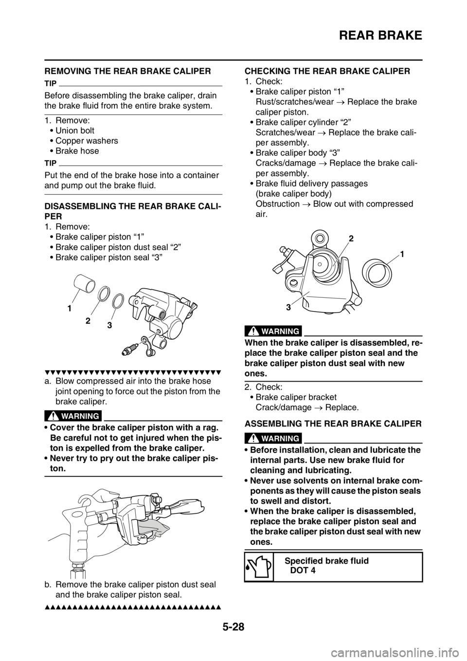
PER
1. Remove:
• Brake caliper piston “1”
• Brake caliper piston dust seal “2”
• Brake caliper piston seal “3”
▼▼▼▼▼▼▼▼▼▼▼▼▼▼▼▼▼▼▼▼▼▼▼▼▼▼▼▼▼▼▼▼
a. Blow compressed air into the brake hose
joint opening to force out the piston from the
brake caliper.
EWA
WARNING
• Cover the brake caliper piston with a rag.
Be careful not to get injured when the pis-
ton is expelled from the brake caliper.
• Never try to pry out the brake caliper pis-
ton.
b. Remove the brake caliper piston dust seal
and the brake caliper piston seal.
▲▲▲▲▲▲▲▲▲▲▲▲▲▲▲▲▲▲▲▲▲▲▲▲▲▲▲▲▲▲▲▲
EAS2GBB185CHECKING THE REAR BRAKE CALIPER
1. Check:
• Brake caliper piston “1”
Rust/scratches/wear Replace the brake
caliper piston.
• Brake caliper cylinder “2”
Scratches/wear Replace the brake cali-
per assembly.
• Brake caliper body “3”
Cracks/damage Replace the brake cali-
per assembly.
• Brake fluid delivery passages
(brake caliper body)
Obstruction Blow out with compressed
air.
EWA
WARNING
When the brake caliper is disassembled, re-
place the brake caliper piston seal and the
brake caliper piston dust seal with new
ones.
2. Check:
• Brake caliper bracket
Crack/damage Replace.
EAS2GBB186ASSEMBLING THE REAR BRAKE CALIPEREWA
WARNING
• Before installation, clean and lubricate the
internal parts. Use new brake fluid for
cleaning and lubricating.
• Never use solvents on internal brake com-
ponents as they will cause the piston seals
to swell and distort.
• When the brake caliper is disassembled,
replace the brake caliper piston seal and
the brake caliper piston dust seal with new
ones.
2
3
1
Specified brake fluid
DOT 4
1 2
3
Page 184 of 432
REAR BRAKE
5-30
EWA
WARNING
• Use only the designated brake fluid. Other
brake fluids may cause the rubber seals to
deteriorate, causing leakage and poor
brake performance.
• Refill with the same type of brake fluid that
is already in the system. Mixing brake flu-
ids may result in a harmful chemical reac-
tion, leading to poor brake performance.
• When refilling, be careful that water does
not enter the brake fluid reservoir. Water
will significantly lower the boiling point of
the brake fluid and could cause vapor
lock.
ECA
NOTICE
Brake fluid may damage painted surfaces
and plastic parts. Therefore, always clean
up any spilt brake fluid immediately.
5. Bleed:
• Brake system
Refer to “BLEEDING THE BRAKE SYS-
TEM” on page 3-25.
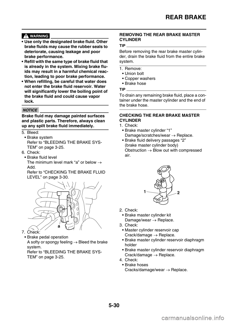
6. Check:
• Brake fluid level
The minimum level mark “a” or below
Add.
Refer to “CHECKING THE BRAKE FLUID
LEVEL” on page 3-30.
7. Check:
• Brake pedal operation
A softy or spongy feeling Bleed the brake
system.
Refer to “BLEEDING THE BRAKE SYS-
TEM” on page 3-25.
EAS2GBB189REMOVING THE REAR BRAKE MASTER
CYLINDER
TIP
Before removing the rear brake master cylin-
der, drain the brake fluid from the entire brake
system.
1. Remove:
• Union bolt
• Copper washers
• Brake hose
TIP
To drain any remaining brake fluid, place a con-
tainer under the master cylinder and the end of
the brake hose.
EAS2GBB190CHECKING THE REAR BRAKE MASTER
CYLINDER
1. Check:
• Brake master cylinder “1”
Damage/scratches/wear Replace.
• Brake fluid delivery passages “2”
(brake master cylinder body)
Obstruction Blow out with compressed
air.
2. Check:
• Brake master cylinder kit
Damage/wear Replace.
3. Check:
• Master cylinder reservoir cap
Crack/damage Replace.
• Brake master cylinder reservoir diaphragm
holder
• Brake master cylinder reservoir diaphragm
Crack/damage Replace.
4. Check:
• Brake hoses
Cracks/damage/wear Replace.
a
1
2
Page 196 of 432
FRONT FORK
5-42
EAS2GBB198REMOVING THE FRONT FORK LEGS
1. Use a suitable stand to raise the front wheel
off the ground.
EWA
WARNING
Securely support the vehicle so that there is
no danger of it falling over.
TIP
Record the adjusting screw setting position be-
fore loosening the adjuster and the base valve.
2. Loosen:
• Upper bracket pinch bolts
• Damper assembly
• Lower bracket pinch bolts
EWA
WARNING
Before loosening the upper and lower
bracket pinch bolts, support the front fork
leg.
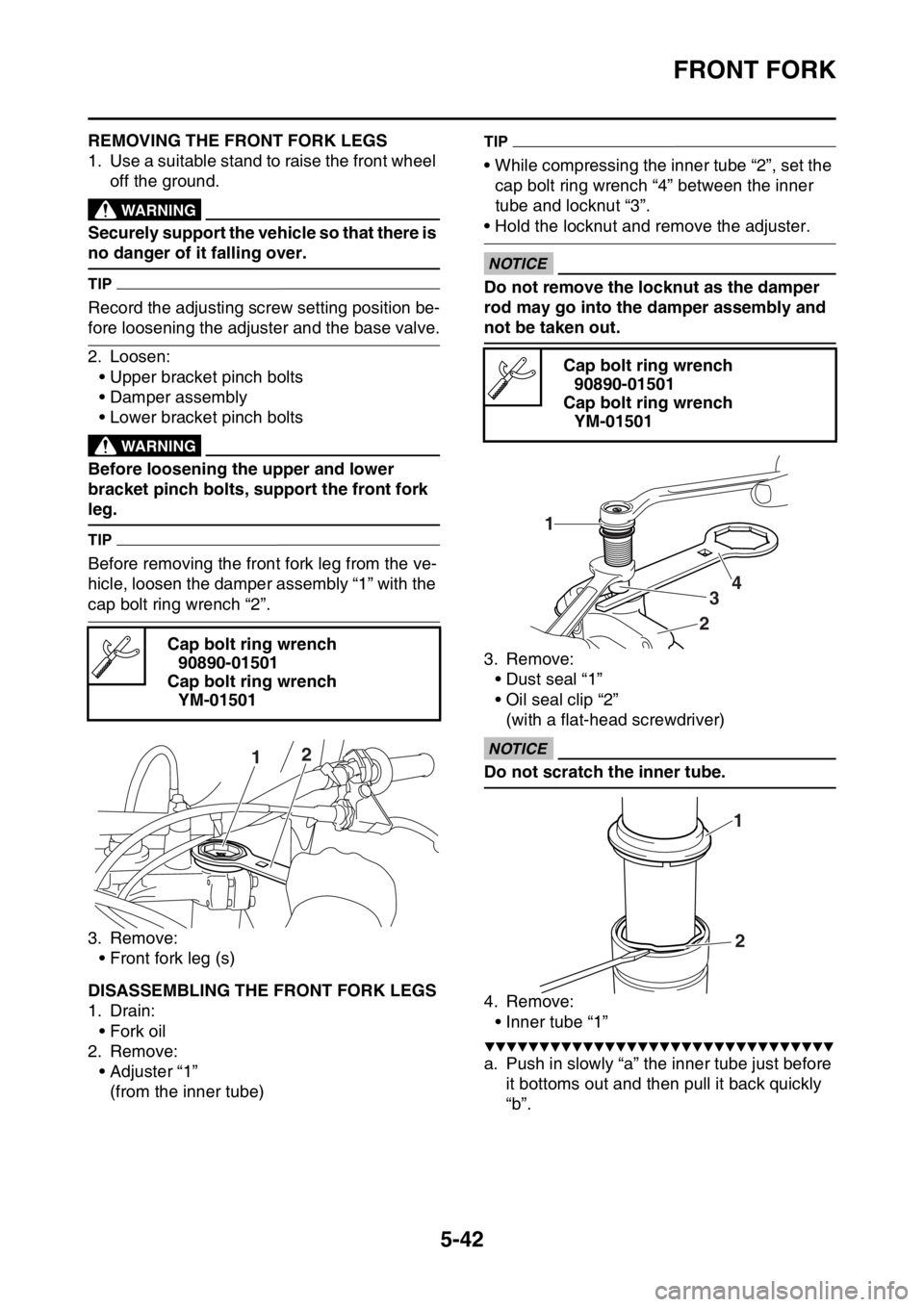
TIP
Before removing the front fork leg from the ve-
hicle, loosen the damper assembly “1” with the
cap bolt ring wrench “2”.
3. Remove:
• Front fork leg (s)
EAS2GBB199DISASSEMBLING THE FRONT FORK LEGS
1. Drain:
• Fork oil
2. Remove:
• Adjuster “1”
(from the inner tube)
TIP
• While compressing the inner tube “2”, set the
cap bolt ring wrench “4” between the inner
tube and locknut “3”.
• Hold the locknut and remove the adjuster.
ECA
NOTICE
Do not remove the locknut as the damper
rod may go into the damper assembly and
not be taken out.
3. Remove:
• Dust seal “1”
• Oil seal clip “2”
(with a flat-head screwdriver)
ECA
NOTICE
Do not scratch the inner tube.
4. Remove:
• Inner tube “1”
▼▼▼▼▼▼▼▼▼▼▼▼▼▼▼▼▼▼▼▼▼▼▼▼▼▼▼▼▼▼▼▼
a. Push in slowly “a” the inner tube just before
it bottoms out and then pull it back quickly
“b”. Cap bolt ring wrench
90890-01501
Cap bolt ring wrench
YM-01501
12
Cap bolt ring wrench
90890-01501
Cap bolt ring wrench
YM-01501
1
234
1
2