engine coolant YAMAHA WR 250F 2017 User Guide
[x] Cancel search | Manufacturer: YAMAHA, Model Year: 2017, Model line: WR 250F, Model: YAMAHA WR 250F 2017Pages: 432, PDF Size: 14.14 MB
Page 111 of 432
ENGINE
3-11
5. Install:
• Copper washer
• Coolant drain bolt
6. Pour coolant.
EWA
WARNING
• If coolant splashes in your eyes, thorough-
ly wash them with water and consult a
doctor.
• If coolant splashes on your clothes, quick-
ly wash it away with water and then with
soap and water.
• If coolant is swallowed, induce vomiting
and get immediate medical attention.
ECA
NOTICE
• Adding water instead of coolant lowers the
antifreeze content of the coolant. If water
is used instead of coolant check, and if
necessary, correct the antifreeze concen-
tration of the coolant.
• Use only distilled water. However, if dis-
tilled water is not available, soft water may
be used.
• If coolant comes into contact with painted
surfaces, immediately wash them with wa-
ter.
• Do not mix different types of antifreeze.
7. Install:
• Radiator cap
8. Start the engine, warm this up for 3 minutes,
stop it, and then wait for it to cool down.
9. Check:
• Coolant level
Refer to “CHECKING THE COOLANT LEV-
EL” on page 3-10.
EAS2GBB085CHECKING THE RADIATOR CAP
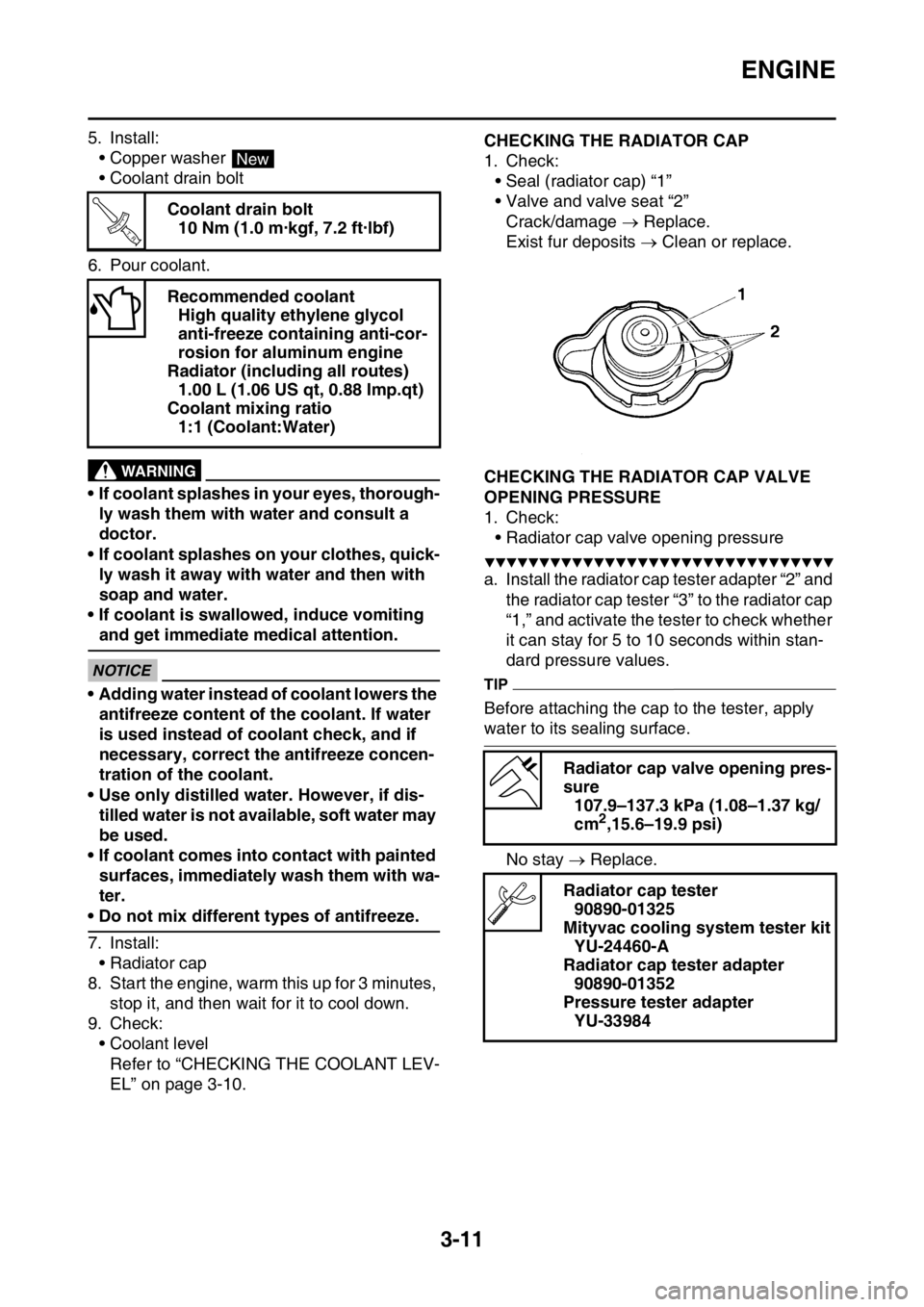
1. Check:
• Seal (radiator cap) “1”
• Valve and valve seat “2”
Crack/damage Replace.
Exist fur deposits Clean or replace.
EAS2GBB086CHECKING THE RADIATOR CAP VALVE
OPENING PRESSURE
1. Check:
• Radiator cap valve opening pressure
▼▼▼▼▼▼▼▼▼▼▼▼▼▼▼▼▼▼▼▼▼▼▼▼▼▼▼▼▼▼▼▼
a. Install the radiator cap tester adapter “2” and
the radiator cap tester “3” to the radiator cap
“1,” and activate the tester to check whether
it can stay for 5 to 10 seconds within stan-
dard pressure values.
TIP
Before attaching the cap to the tester, apply
water to its sealing surface.
No stay Replace. Coolant drain bolt
10 Nm (1.0 m·kgf, 7.2 ft·lbf)
Recommended coolant
High quality ethylene glycol
anti-freeze containing anti-cor-
rosion for aluminum engine
Radiator (including all routes)
1.00 L (1.06 US qt, 0.88 Imp.qt)
Coolant mixing ratio
1:1 (Coolant:Water)
New
T R..
Radiator cap valve opening pres-
sure
107.9–137.3 kPa (1.08–1.37 kg/
cm
2,15.6–19.9 psi)
Radiator cap tester
90890-01325
Mityvac cooling system tester kit
YU-24460-A
Radiator cap tester adapter
90890-01352
Pressure tester adapter
YU-33984
Page 112 of 432
ENGINE
3-12
▲▲▲▲▲▲▲▲▲▲▲▲▲▲▲▲▲▲▲▲▲▲▲▲▲▲▲▲▲▲▲▲
EAS2GBB087CHECKING THE COOLANT CIRCULATORY
SYSTEM FOR LEAKS
1. Check:
• Coolant level
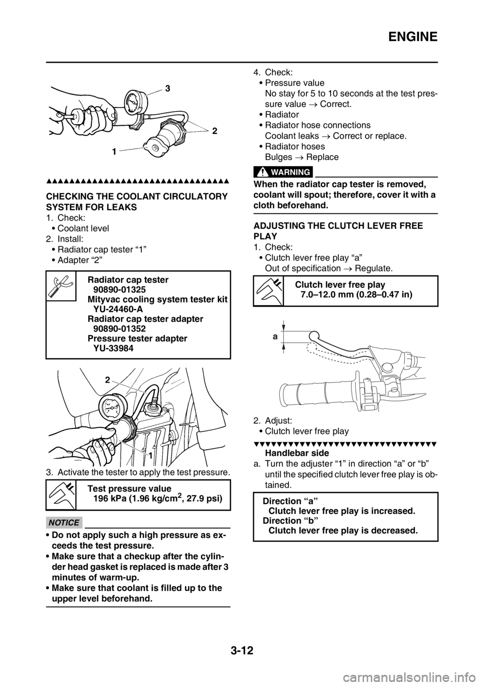
2. Install:
• Radiator cap tester “1”
• Adapter “2”
3. Activate the tester to apply the test pressure.
ECA
NOTICE
• Do not apply such a high pressure as ex-
ceeds the test pressure.
• Make sure that a checkup after the cylin-
der head gasket is replaced is made after 3
minutes of warm-up.
• Make sure that coolant is filled up to the
upper level beforehand.4. Check:
• Pressure value
No stay for 5 to 10 seconds at the test pres-
sure value Correct.
• Radiator
• Radiator hose connections
Coolant leaks Correct or replace.
• Radiator hoses
Bulges Replace
EWA
WARNING
When the radiator cap tester is removed,
coolant will spout; therefore, cover it with a
cloth beforehand.
EAS2GBB088ADJUSTING THE CLUTCH LEVER FREE
PLAY
1. Check:
• Clutch lever free play “a”
Out of specification Regulate.
2. Adjust:
• Clutch lever free play
▼▼▼▼▼▼▼▼▼▼▼▼▼▼▼▼▼▼▼▼▼▼▼▼▼▼▼▼▼▼▼▼
Handlebar side
a. Turn the adjuster “1” in direction “a” or “b”
until the specified clutch lever free play is ob-
tained. Radiator cap tester
90890-01325
Mityvac cooling system tester kit
YU-24460-A
Radiator cap tester adapter
90890-01352
Pressure tester adapter
YU-33984
Test pressure value
196 kPa (1.96 kg/cm
2, 27.9 psi)
Clutch lever free play
7.0–12.0 mm (0.28–0.47 in)
Direction “a”
Clutch lever free play is increased.
Direction “b”
Clutch lever free play is decreased.
Page 232 of 432
ENGINE REMOVAL
6-3
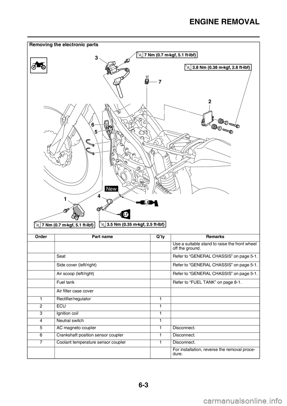
Removing the electronic parts
Order Part name Q’ty Remarks
Use a suitable stand to raise the front wheel
off the ground.
Seat Refer to “GENERAL CHASSIS” on page 5-1.
Side cover (left/right) Refer to “GENERAL CHASSIS” on page 5-1.
Air scoop (left/right) Refer to “GENERAL CHASSIS” on page 5-1.
Fuel tank Refer to “FUEL TANK” on page 8-1.
Air filter case cover
1 Rectifier/regulator 1
2ECU 1
3 Ignition coil 1
4 Neutral switch 1
5 AC magneto coupler 1 Disconnect.
6 Crankshaft position sensor coupler 1 Disconnect.
7 Coolant temperature sensor coupler 1 Disconnect.
For installation, reverse the removal proce-
dure.
T.R.
T.R.
T.R.T.R.
7 3
6
5
142
LT
New
LS
Page 249 of 432
CYLINDER HEAD
6-20
EAS2GBB244
CYLINDER HEAD
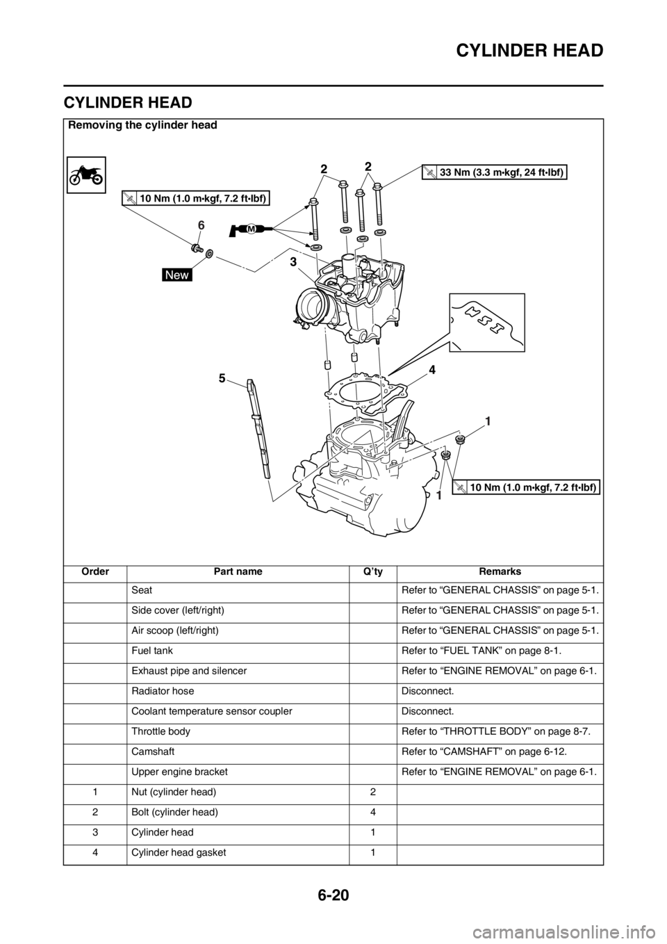
Removing the cylinder head
Order Part name Q’ty Remarks
Seat Refer to “GENERAL CHASSIS” on page 5-1.
Side cover (left/right) Refer to “GENERAL CHASSIS” on page 5-1.
Air scoop (left/right) Refer to “GENERAL CHASSIS” on page 5-1.
Fuel tank Refer to “FUEL TANK” on page 8-1.
Exhaust pipe and silencer Refer to “ENGINE REMOVAL” on page 6-1.
Radiator hose Disconnect.
Coolant temperature sensor coupler Disconnect.
Throttle body Refer to “THROTTLE BODY” on page 8-7.
Camshaft Refer to “CAMSHAFT” on page 6-12.
Upper engine bracket Refer to “ENGINE REMOVAL” on page 6-1.
1 Nut (cylinder head) 2
2 Bolt (cylinder head) 4
3 Cylinder head 1
4 Cylinder head gasket 1
6
10 Nm (1.0 m kgf, 7.2 ft Ibf)T.R.
33 Nm (3.3 m kgf, 24 ft Ibf)T.R.
10 Nm (1.0 m kgf, 7.2 ft Ibf)T.R.
Page 273 of 432
CLUTCH
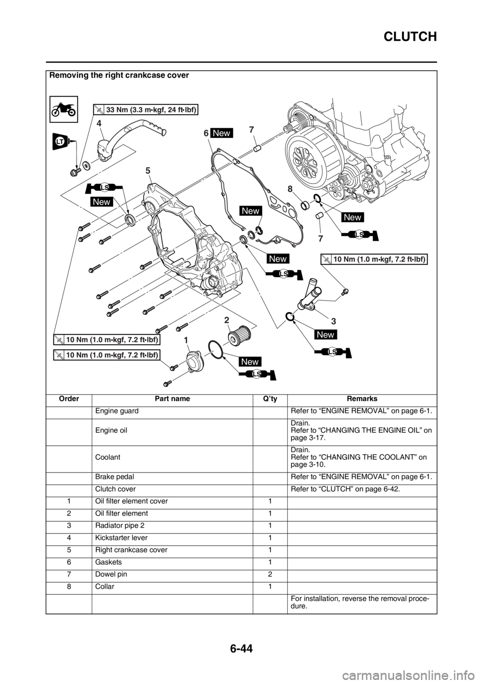
6-44
Removing the right crankcase cover
Order Part name Q’ty Remarks
Engine guard Refer to “ENGINE REMOVAL” on page 6-1.
Engine oilDrain.
Refer to “CHANGING THE ENGINE OIL” on
page 3-17.
CoolantDrain.
Refer to “CHANGING THE COOLANT” on
page 3-10.
Brake pedal Refer to “ENGINE REMOVAL” on page 6-1.
Clutch cover Refer to “CLUTCH” on page 6-42.
1 Oil filter element cover 1
2 Oil filter element 1
3 Radiator pipe 2 1
4 Kickstarter lever 1
5 Right crankcase cover 1
6 Gaskets 1
7 Dowel pin 2
8Collar 1
For installation, reverse the removal proce-
dure.
T.R.
LS
New
New
67
2
5
4
1
7 8
New
3
LS
New
New
LS
NewNew
LT
LS
Page 316 of 432
RADIATOR
7-1
EAS2GBB328
TIP
This section is intended for those who have basic knowledge and skill concerning the servicing of
Yamaha motorcycles (e.g., Yamaha dealers, service engineers, etc.). Those who have little knowl-
edge and skill concerning servicing are requested not to undertake inspection, adjustment, disas-
sembly, or reassembly only by reference to this manual. It may lead to servicing trouble and
mechanical damage.
EAS2GBB329
RADIATOR
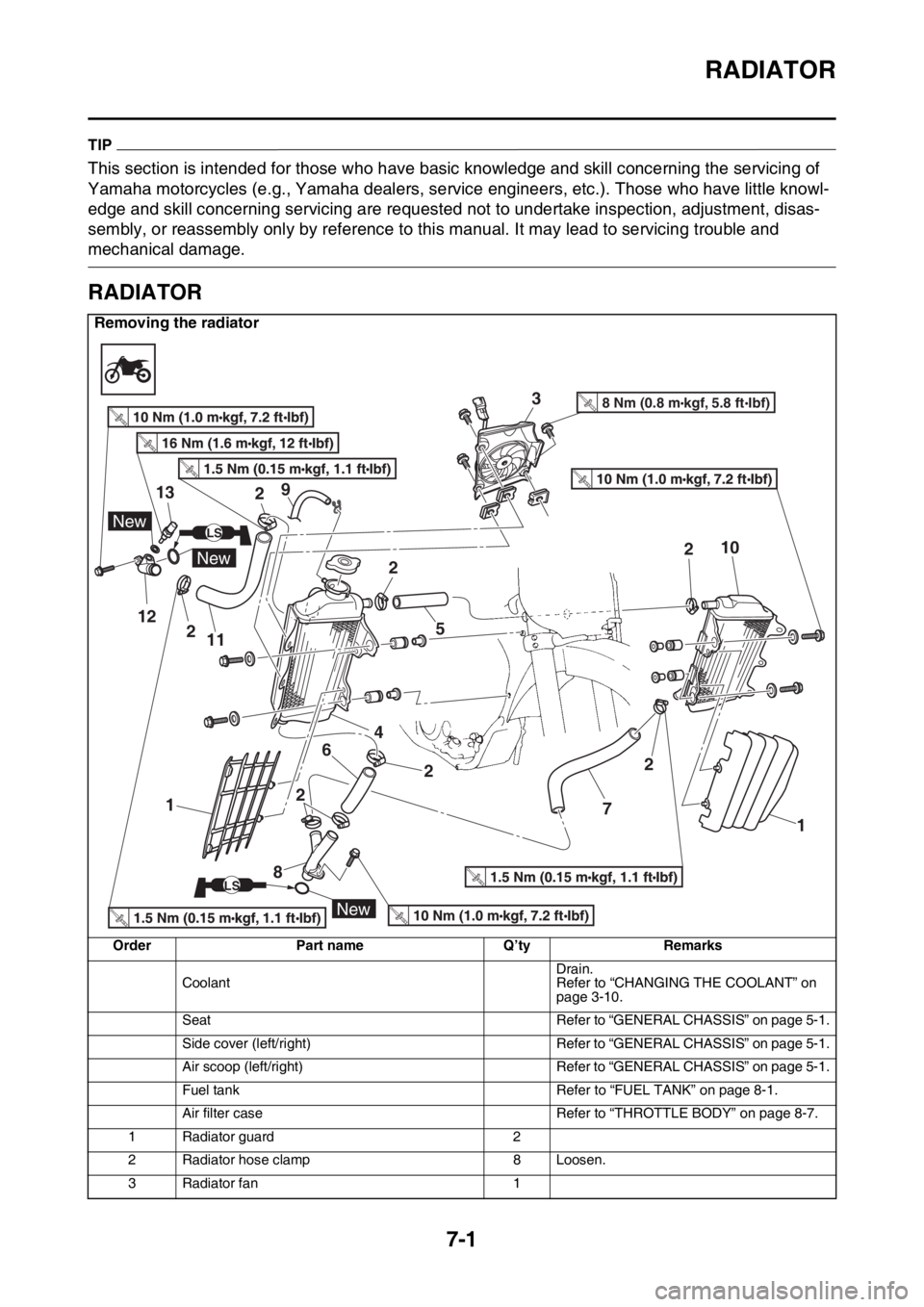
Removing the radiator
Order Part name Q’ty Remarks
CoolantDrain.
Refer to “CHANGING THE COOLANT” on
page 3-10.
Seat Refer to “GENERAL CHASSIS” on page 5-1.
Side cover (left/right) Refer to “GENERAL CHASSIS” on page 5-1.
Air scoop (left/right) Refer to “GENERAL CHASSIS” on page 5-1.
Fuel tank Refer to “FUEL TANK” on page 8-1.
Air filter case Refer to “THROTTLE BODY” on page 8-7.
1 Radiator guard 2
2 Radiator hose clamp 8 Loosen.
3 Radiator fan 1
12
13
New
New
New
LS
LS
3
458 Nm (0.8 m kgf, 5.8 ft Ibf)T.R.
6
7
89
10
112
2
2
2 22 2
1 1
Page 319 of 432
WATER PUMP
7-4
EAS2GBB332
WATER PUMP
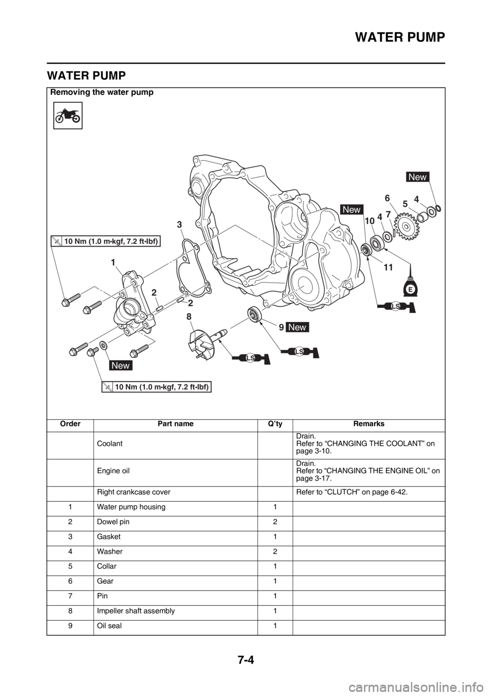
Removing the water pump
Order Part name Q’ty Remarks
CoolantDrain.
Refer to “CHANGING THE COOLANT” on
page 3-10.
Engine oilDrain.
Refer to “CHANGING THE ENGINE OIL” on
page 3-17.
Right crankcase cover Refer to “CLUTCH” on page 6-42.
1 Water pump housing 1
2 Dowel pin 2
3Gasket 1
4Washer 2
5Collar 1
6Gear 1
7Pin 1
8 Impeller shaft assembly 1
9 Oil seal 1
9
8
2
2
3
1
10
6
7
5
4
4
10 Nm (1.0 mkgf, 7.2 ftIbf)T.R.
10 Nm (1.0 mkgf, 7.2 ftIbf)T.R.
New
New
New
11
New
E
LS
LS
LS
Page 321 of 432
WATER PUMP
7-6
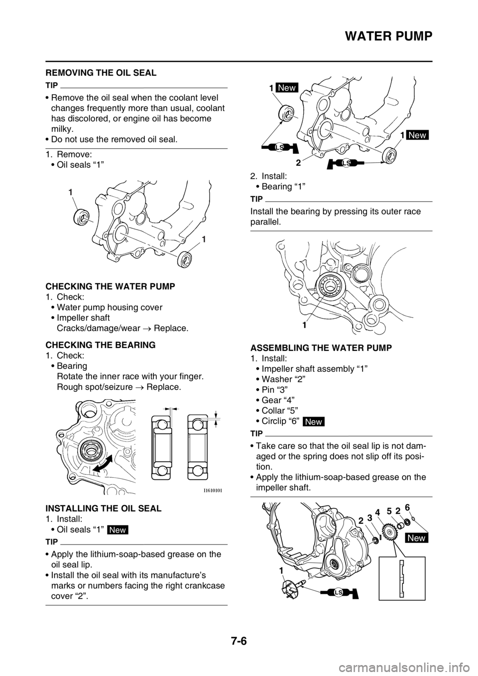
EAS2GBB333REMOVING THE OIL SEAL
TIP
• Remove the oil seal when the coolant level
changes frequently more than usual, coolant
has discolored, or engine oil has become
milky.
• Do not use the removed oil seal.
1. Remove:
• Oil seals “1”
EAS2GBB334CHECKING THE WATER PUMP
1. Check:
• Water pump housing cover
• Impeller shaft
Cracks/damage/wear Replace.
EAS2GBB335CHECKING THE BEARING
1. Check:
• Bearing
Rotate the inner race with your finger.
Rough spot/seizure Replace.
EAS2GBB336INSTALLING THE OIL SEAL
1. Install:
• Oil seals “1”
TIP
• Apply the lithium-soap-based grease on the
oil seal lip.
• Install the oil seal with its manufacture’s
marks or numbers facing the right crankcase
cover “2”.2. Install:
• Bearing “1”
TIP
Install the bearing by pressing its outer race
parallel.
EAS2GBB337ASSEMBLING THE WATER PUMP
1. Install:
• Impeller shaft assembly “1”
• Washer “2”
•Pin “3”
• Gear “4”
• Collar “5”
• Circlip “6”
TIP
• Take care so that the oil seal lip is not dam-
aged or the spring does not slip off its posi-
tion.
• Apply the lithium-soap-based grease on the
impeller shaft.
1 1
New
1 1New
New
LS
LS2
New
1
2
52346
New
LS
Page 361 of 432

COOLING SYSTEM
9-25
1. Joint connector
2. Joint connector
3. Joint connector
7. Main relay
9. Battery
10.Frame ground
11.Starter relay
12.Main fuse
22.ECU (engine control unit)
27.Radiator fan motor relay
28.Radiator fan motor fuse
29.Radiator fan motor
30.Joint connector
32.Coolant temperature sensor
48.Frame ground
Page 365 of 432

FUEL INJECTION SYSTEM
9-29
1. Joint connector
2. Joint connector
3. Joint connector
4. AC magneto
7. Main relay
9. Battery
10.Frame ground
11.Starter relay
12.Main fuse
15.Indicator light
16.Engine trouble warning light
22.ECU (engine control unit)
25.Injector
30.Joint connector
31.Intake air temperature sensor
32.Coolant temperature sensor
33.Throttle position sensor
34.Intake air pressure sensor
35.Lean angle sensor
36.Engine stop switch
37.Neutral switch
38.Diode
39.Starting circuit cut-off relay
40.Clutch switch
42.Joint connector
48.Frame ground