relay YAMAHA WR 250F 2017 User Guide
[x] Cancel search | Manufacturer: YAMAHA, Model Year: 2017, Model line: WR 250F, Model: YAMAHA WR 250F 2017Pages: 432, PDF Size: 14.14 MB
Page 214 of 432
REAR SHOCK ABSORBER ASSEMBLY
5-60
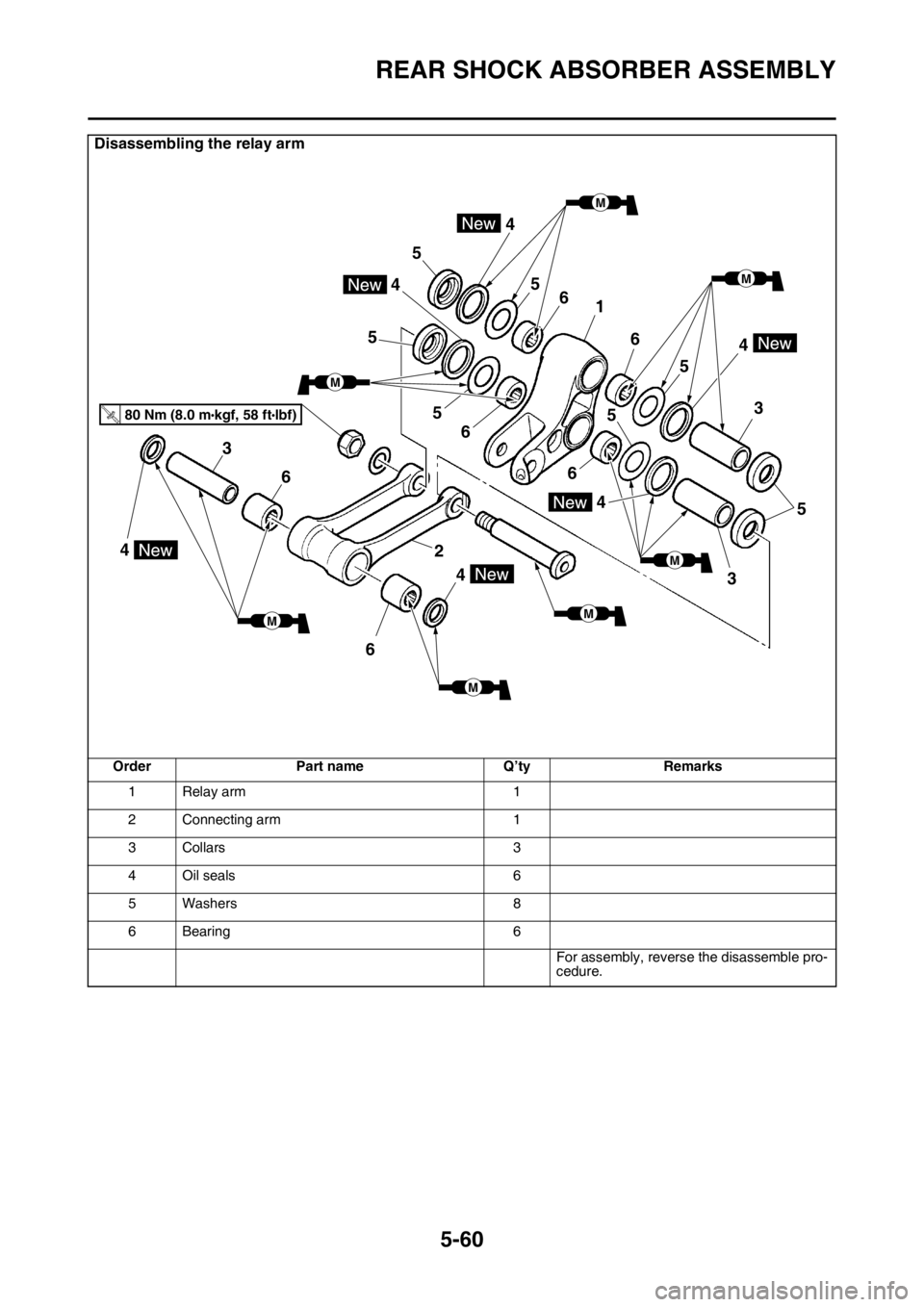
Disassembling the relay arm
Order Part name Q’ty Remarks
1 Relay arm 1
2 Connecting arm 1
3Collars 3
4Oil seals 6
5Washers 8
6 Bearing 6
For assembly, reverse the disassemble pro-
cedure.
5
3
5
6
165
4
5
5
4
5
6
6
5
4
3
2
4
6
6
3
4
4
T.R.80 Nm (8.0 mlbf) kgf, 58 ft
M
M
M
M
M MM
Page 216 of 432
REAR SHOCK ABSORBER ASSEMBLY
5-62
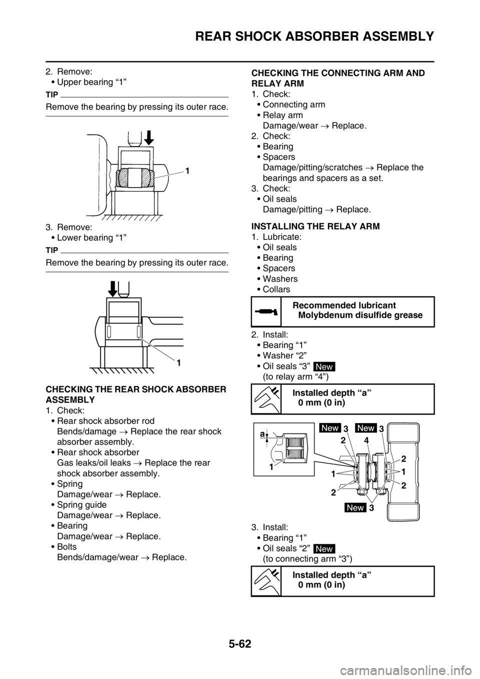
2. Remove:
• Upper bearing “1”
TIP
Remove the bearing by pressing its outer race.
3. Remove:
• Lower bearing “1”
TIP
Remove the bearing by pressing its outer race.
EAS2GBB212CHECKING THE REAR SHOCK ABSORBER
ASSEMBLY
1. Check:
• Rear shock absorber rod
Bends/damage Replace the rear shock
absorber assembly.
• Rear shock absorber
Gas leaks/oil leaks Replace the rear
shock absorber assembly.
•Spring
Damage/wear Replace.
• Spring guide
Damage/wear Replace.
• Bearing
Damage/wear Replace.
•Bolts
Bends/damage/wear Replace.
EAS2GBB213CHECKING THE CONNECTING ARM AND
RELAY ARM
1. Check:
• Connecting arm
• Relay arm
Damage/wear Replace.
2. Check:
• Bearing
• Spacers
Damage/pitting/scratches Replace the
bearings and spacers as a set.
3. Check:
• Oil seals
Damage/pitting Replace.
EAS2GBB214INSTALLING THE RELAY ARM
1. Lubricate:
• Oil seals
• Bearing
• Spacers
• Washers
•Collars
2. Install:
• Bearing “1”
• Washer “2”
• Oil seals “3”
(to relay arm “4”)
3. Install:
• Bearing “1”
• Oil seals “2”
(to connecting arm “3”)
1
Recommended lubricant
Molybdenum disulfide grease
Installed depth “a”
0 mm (0 in)
Installed depth “a”
0 mm (0 in)
New
3 3
43
2 2
22
a
1
11
New
Page 217 of 432
REAR SHOCK ABSORBER ASSEMBLY
5-63
EAS2GBB215INSTALLING THE REAR SHOCK ABSORB-
ER ASSEMBLY
1. Lubricate:
• Bearing (lower side)
•Dust seal
•Collars
• Bushing
ECA
NOTICE
Do not apply the grease to the bearing outer
race because it will wear the rear shock ab-
sorber surface on which the bearing is
press fitted.
2. Lubricate:
• O-ring
3. Install:
• Bearing
• Stopper ring
(to rear shock absorber assembly (upper
side))
TIP
• Install the bearing parallel until the stopper
ring groove appears by pressing its outer
race.
• After installing the stopper ring, push back the
bearing unit it contacts the stopper ring.
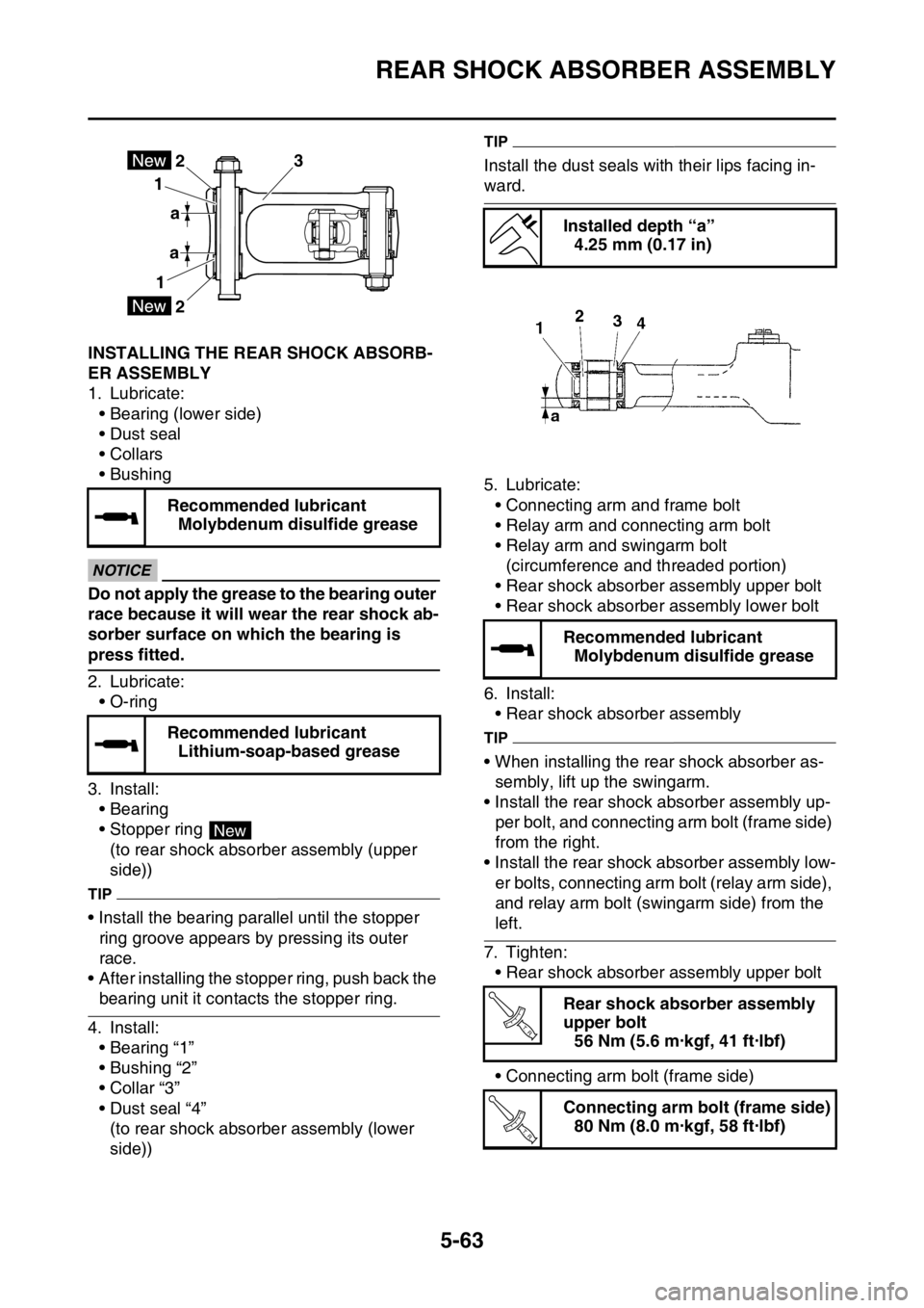
4. Install:
• Bearing “1”
• Bushing “2”
• Collar “3”
• Dust seal “4”
(to rear shock absorber assembly (lower
side))
TIP
Install the dust seals with their lips facing in-
ward.
5. Lubricate:
• Connecting arm and frame bolt
• Relay arm and connecting arm bolt
• Relay arm and swingarm bolt
(circumference and threaded portion)
• Rear shock absorber assembly upper bolt
• Rear shock absorber assembly lower bolt
6. Install:
• Rear shock absorber assembly
TIP
• When installing the rear shock absorber as-
sembly, lift up the swingarm.
• Install the rear shock absorber assembly up-
per bolt, and connecting arm bolt (frame side)
from the right.
• Install the rear shock absorber assembly low-
er bolts, connecting arm bolt (relay arm side),
and relay arm bolt (swingarm side) from the
left.
7. Tighten:
• Rear shock absorber assembly upper bolt
• Connecting arm bolt (frame side) Recommended lubricant
Molybdenum disulfide grease
Recommended lubricant
Lithium-soap-based grease
3
a 1
12
a
2
New
Installed depth “a”
4.25 mm (0.17 in)
Recommended lubricant
Molybdenum disulfide grease
Rear shock absorber assembly
upper bolt
56 Nm (5.6 m·kgf, 41 ft·lbf)
Connecting arm bolt (frame side)
80 Nm (8.0 m·kgf, 58 ft·lbf)
T R..
T R..
Page 218 of 432
REAR SHOCK ABSORBER ASSEMBLY
5-64
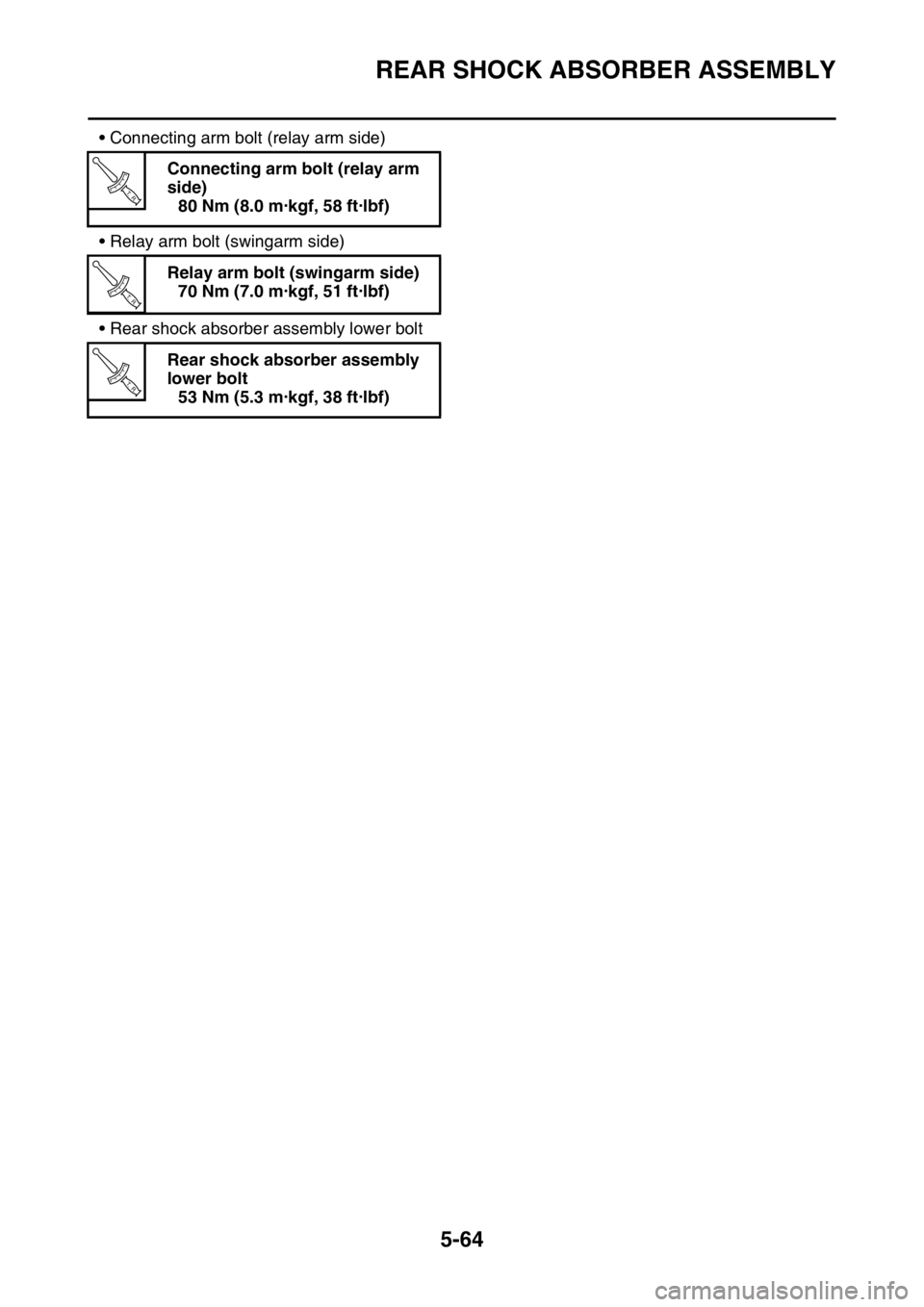
• Connecting arm bolt (relay arm side)
• Relay arm bolt (swingarm side)
• Rear shock absorber assembly lower boltConnecting arm bolt (relay arm
side)
80 Nm (8.0 m·kgf, 58 ft·lbf)
Relay arm bolt (swingarm side)
70 Nm (7.0 m·kgf, 51 ft·lbf)
Rear shock absorber assembly
lower bolt
53 Nm (5.3 m·kgf, 38 ft·lbf)
T R..
T R..
T R..
Page 327 of 432
FUEL TANK
8-4
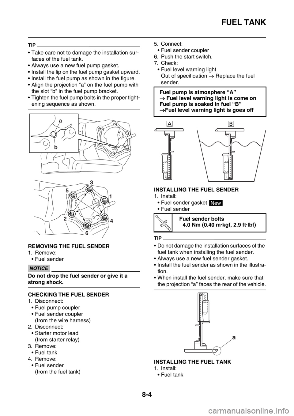
TIP
• Take care not to damage the installation sur-
faces of the fuel tank.
• Always use a new fuel pump gasket.
• Install the lip on the fuel pump gasket upward.
• Install the fuel pump as shown in the figure.
• Align the projection “a” on the fuel pump with
the slot “b” in the fuel pump bracket.
• Tighten the fuel pump bolts in the proper tight-
ening sequence as shown.
EAS2GBB344REMOVING THE FUEL SENDER
1. Remove:
• Fuel sender
ECA
NOTICE
Do not drop the fuel sender or give it a
strong shock.
EAS2GBB345CHECKING THE FUEL SENDER
1. Disconnect:
• Fuel pump coupler
• Fuel sender coupler
(from the wire harness)
2. Disconnect:
• Starter motor lead
(from starter relay)
3. Remove:
• Fuel tank
4. Remove:
• Fuel sender
(from the fuel tank)5. Connect:
• Fuel sender coupler
6. Push the start switch.
7. Check:
• Fuel level warning light
Out of specification Replace the fuel
sender.
EAS2GBB346INSTALLING THE FUEL SENDER
1. Install:
• Fuel sender gasket
• Fuel sender
TIP
• Do not damage the installation surfaces of the
fuel tank when installing the fuel sender.
• Always use a new fuel sender gasket.
• Install the fuel sender as shown in the illustra-
tion.
• When install the fuel sender, make sure that
the projection “a” faces the rear of the vehicle.
EAS2GBB347INSTALLING THE FUEL TANK
1. Install:
• Fuel tank
a
b
4 1
2
6
53
Fuel pump is atmosphere “A”
Fuel level warning light is come on
Fuel pump is soaked in fuel “B”
Fuel level warning light is goes off
Fuel sender bolts
4.0 Nm (0.40 m·kgf, 2.9 ft·lbf)
New
T R..
a
Page 336 of 432

ELECTRICAL COMPONENTS....................................................................... 9-60
CHECKING THE SWITCHES .................................................................. 9-64
CHECKING THE BULBS AND BULB SOCKETS .................................... 9-67
CHECKING THE FUSES ......................................................................... 9-68
CHECKING AND CHARGING THE BATTERY ........................................ 9-69
CHECKING THE RELAYS ....................................................................... 9-72
CHECKING THE DIODE .......................................................................... 9-73
CHECKING THE IGNITION SPARK GAP................................................ 9-73
CHECKING THE SPARK PLUG CAP ...................................................... 9-74
CHECKING THE IGNITION COIL ............................................................ 9-74
CHECKING THE CRANKSHAFT POSITION SENSOR........................... 9-75
CHECKING THE LEAN ANGLE SENSOR............................................... 9-75
CHECKING THE STARTER MOTOR OPERATION ................................ 9-76
CHECKING THE STATOR COIL ............................................................. 9-76
CHECKING THE RECTIFIER/REGULATOR ........................................... 9-76
CHECKING THE SPEED SENSOR ......................................................... 9-77
CHECKING THE FUEL SENDER ............................................................ 9-77
CHECKING THE RESISTER ................................................................... 9-78
CHECKING THE RADIATOR FAN MOTOR ............................................ 9-78
CHECKING THE COOLANT TEMPERATURE SENSOR........................ 9-78
CHECKING THE THROTTLE POSITION SENSOR ................................ 9-79
CHECKING THE THROTTLE POSITION SENSOR INPUT VOLTAGE .. 9-80
CHECKING THE INTAKE AIR PRESSURE SENSOR ............................ 9-80
CHECKING THE INTAKE AIR TEMPERATURE SENSOR ..................... 9-80
CHECKING THE FUEL INJECTOR ......................................................... 9-81
Page 339 of 432

IGNITION SYSTEM
9-3
1. Joint connector
2. Joint connector
4. AC magneto
9. Battery
10.Frame ground
11.Starter relay
12.Main fuse
22.ECU (engine control unit)
23.Ignition coil
24.Spark plug
30.Joint connector
35.Lean angle sensor
36.Engine stop switch
48.Frame ground
49.Ignition coil sub-lead
Page 343 of 432

ELECTRIC STARTING SYSTEM
9-7
1. Joint connector
2. Joint connector
3. Joint connector
7. Main relay
9. Battery
10.Frame ground
11.Starter relay
12.Main fuse
13.Starter motor
14.Starter relay diode
22.ECU (engine control unit)
30.Joint connector
36.Engine stop switch
37.Neutral switch
38.Diode
39.Starting circuit cut-off relay
40.Clutch switch
41.Start switch
48.Frame ground
Page 344 of 432
ELECTRIC STARTING SYSTEM
9-8
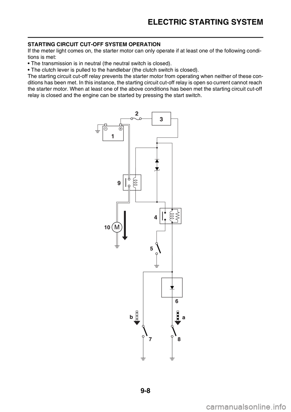
EAS2GBB361STARTING CIRCUIT CUT-OFF SYSTEM OPERATION
If the meter light comes on, the starter motor can only operate if at least one of the following condi-
tions is met:
• The transmission is in neutral (the neutral switch is closed).
• The clutch lever is pulled to the handlebar (the clutch switch is closed).
The starting circuit cut-off relay prevents the starter motor from operating when neither of these con-
ditions has been met. In this instance, the starting circuit cut-off relay is open so current cannot reach
the starter motor. When at least one of the above conditions has been met the starting circuit cut-off
relay is closed and the engine can be started by pressing the start switch.
Page 345 of 432

ELECTRIC STARTING SYSTEM
9-9
a. WHEN THE TRANSMISSION IS IN NEU-
TRAL
b. WHEN THE CLUTCH LEVER IS PULLED
TO THE HANDLEBAR
1. Battery
2. Main fuse
3. Main relay
4. Starting circuit cut-off relay
5. Start switch
6. Diode
7. Clutch switch
8. Neutral switch
9. Starter relay
10.Starter motor