sensor YAMAHA WR 250F 2017 Owner's Manual
[x] Cancel search | Manufacturer: YAMAHA, Model Year: 2017, Model line: WR 250F, Model: YAMAHA WR 250F 2017Pages: 432, PDF Size: 14.14 MB
Page 296 of 432
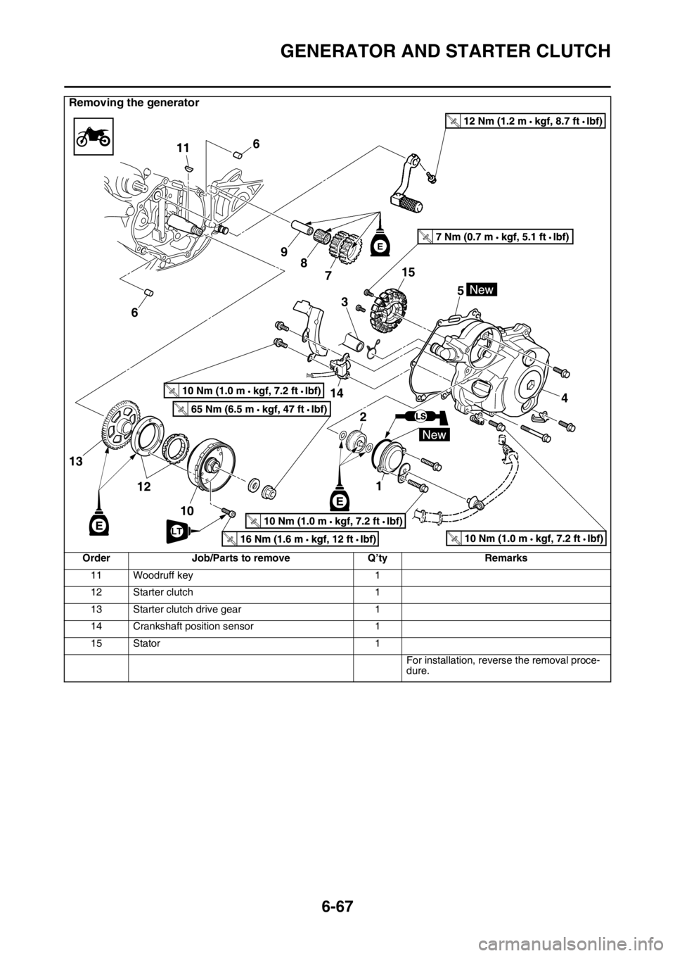
GENERATOR AND STARTER CLUTCH
6-67
11 Woodruff key 1
12 Starter clutch 1
13 Starter clutch drive gear 1
14 Crankshaft position sensor 1
15 Stator 1
For installation, reverse the removal proce-
dure.
Removing the generator
Order Job/Parts to remove Q’ty Remarks
T R..
T R..
6
611
9
8
7
2
3
1
14
4 5
12
10
13
T R..
T R..
T R..LTT R..
T R..
15
Page 298 of 432
GENERATOR AND STARTER CLUTCH
6-69
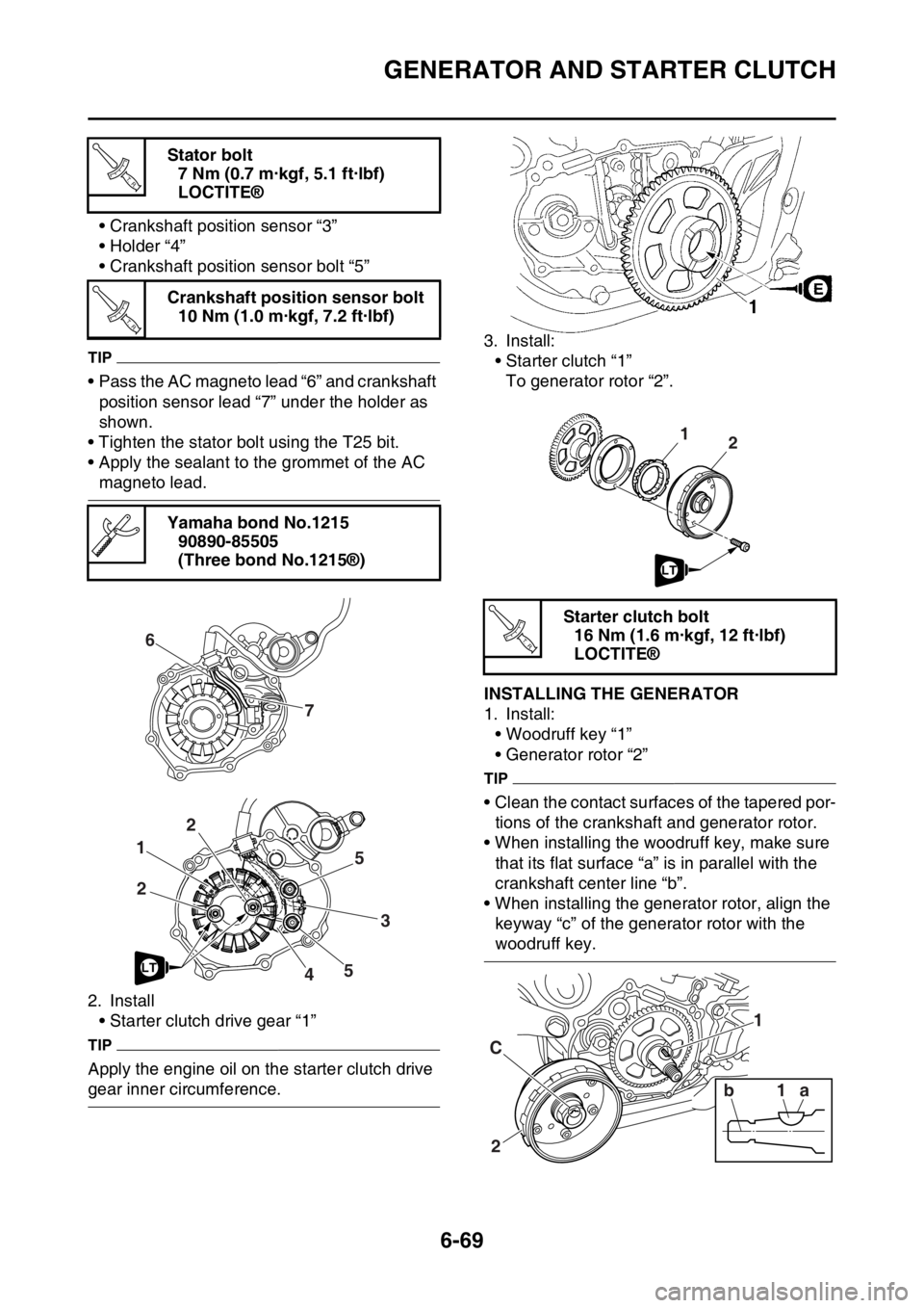
• Crankshaft position sensor “3”
• Holder “4”
• Crankshaft position sensor bolt “5”
TIP
• Pass the AC magneto lead “6” and crankshaft
position sensor lead “7” under the holder as
shown.
• Tighten the stator bolt using the T25 bit.
• Apply the sealant to the grommet of the AC
magneto lead.
2. Install
• Starter clutch drive gear “1”
TIP
Apply the engine oil on the starter clutch drive
gear inner circumference.3. Install:
• Starter clutch “1”
To generator rotor “2”.
EAS2GBB309INSTALLING THE GENERATOR
1. Install:
• Woodruff key “1”
• Generator rotor “2”
TIP
• Clean the contact surfaces of the tapered por-
tions of the crankshaft and generator rotor.
• When installing the woodruff key, make sure
that its flat surface “a” is in parallel with the
crankshaft center line “b”.
• When installing the generator rotor, align the
keyway “c” of the generator rotor with the
woodruff key. Stator bolt
7 Nm (0.7 m·kgf, 5.1 ft·lbf)
LOCTITE®
Crankshaft position sensor bolt
10 Nm (1.0 m·kgf, 7.2 ft·lbf)
Yamaha bond No.1215
90890-85505
(Three bond No.1215®)
T R..
T R..
6
7
1
3
22
5
5
4LT
Starter clutch bolt
16 Nm (1.6 m·kgf, 12 ft·lbf)
LOCTITE®
21
LT
T R..
2 C1 1
1a b
Page 317 of 432
RADIATOR
7-2
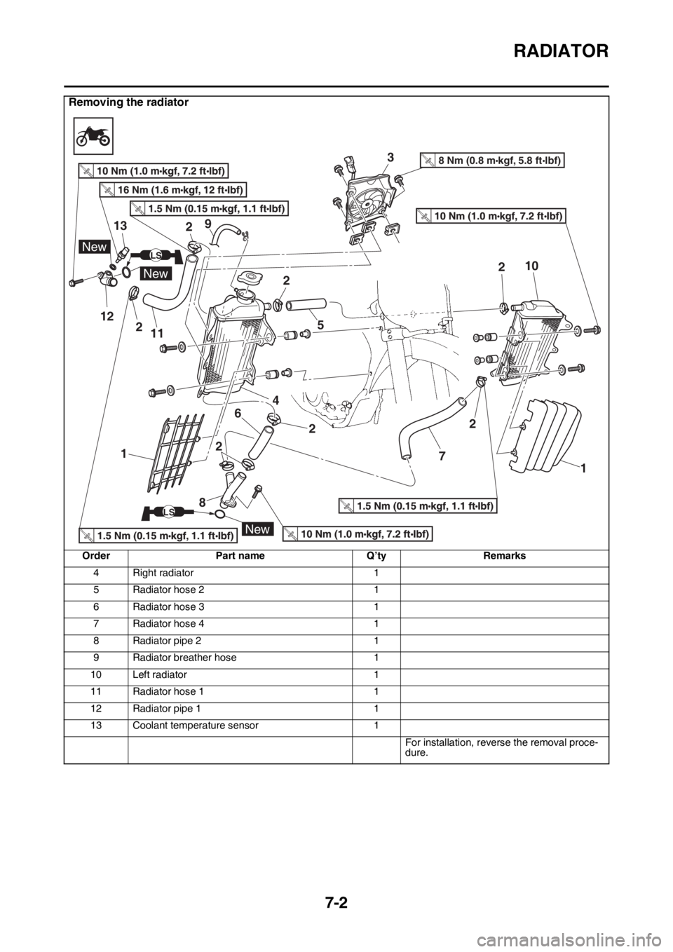
4 Right radiator 1
5 Radiator hose 2 1
6 Radiator hose 3 1
7 Radiator hose 4 1
8 Radiator pipe 2 1
9 Radiator breather hose 1
10 Left radiator 1
11 Radiator hose 1 1
12 Radiator pipe 1 1
13 Coolant temperature sensor 1
For installation, reverse the removal proce-
dure.
Removing the radiator
Order Part name Q’ty Remarks
12
13
New
New
New
LS
LS
3
458 Nm (0.8 m kgf, 5.8 ft Ibf)T.R.
6
7
89
10
112
2
2
2 22 2
1 1
Page 323 of 432

8
FUEL SYSTEM
FUEL TANK...................................................................................................... 8-1
REMOVING THE FUEL TANK ................................................................... 8-3
REMOVING THE FUEL PUMP .................................................................. 8-3
CHECKING THE FUEL PUMP BODY........................................................ 8-3
INSTALLING THE FUEL PUMP ................................................................. 8-3
REMOVING THE FUEL SENDER.............................................................. 8-4
CHECKING THE FUEL SENDER .............................................................. 8-4
INSTALLING THE FUEL SENDER ............................................................ 8-4
INSTALLING THE FUEL TANK.................................................................. 8-4
CHECKING THE FUEL PRESSURE ......................................................... 8-5
CHECKING THE DAMPER ........................................................................ 8-6
CHECKING AND REPLACING THE PROTECTOR .................................. 8-6
THROTTLE BODY............................................................................................ 8-7
CHECKING THE INJECTOR ................................................................... 8-10
CHECKING THE THROTTLE BODY ....................................................... 8-10
CHECKING THE THROTTLE BODY JOINT ............................................ 8-10
ADJUSTING THE THROTTLE POSITION SENSOR............................... 8-11
Page 330 of 432

THROTTLE BODY
8-7
EAS2GBB351
THROTTLE BODY
Removing the throttle body
Order Part name Q’ty Remarks
Seat Refer to “GENERAL CHASSIS” on page 5-1.
Side cover (left/right) Refer to “GENERAL CHASSIS” on page 5-1.
Air scoop (left/right) Refer to “GENERAL CHASSIS” on page 5-1.
Fuel tank Refer to “FUEL TANK” on page 8-1.
ECU Refer to “ENGINE REMOVAL” on page 6-1.
Ignition coil Refer to “ENGINE REMOVAL” on page 6-1.
1 Intake air temperature sensor coupler 1 Disconnect.
2 Breather hose 3 1
3 Air filter case 1
4 Fuel injector coupler 1 Disconnect.
5 Intake air pressure sensor coupler 1 Disconnect.
6 Throttle position sensor coupler 1 Disconnect.
7 Throttle cable cover 1
8 Throttle cable 2
3
1
2
7
11
12
10
9
4
8
6
5
3.5 Nm (0.35 m kgf, 2.5 ft Ibf)T.R.
3.5 Nm (0.35 m kgf, 2.5 ft Ibf)T.R.
7 Nm (0.7 m kgf, 5.1 ft Ibf)T.R.
3.0 Nm (0.30 m kgf, 2.2 ft Ibf)T.R.
10 Nm (1.0 m kgf, 7.2 ft Ibf)T.R.
Page 332 of 432
THROTTLE BODY
8-9
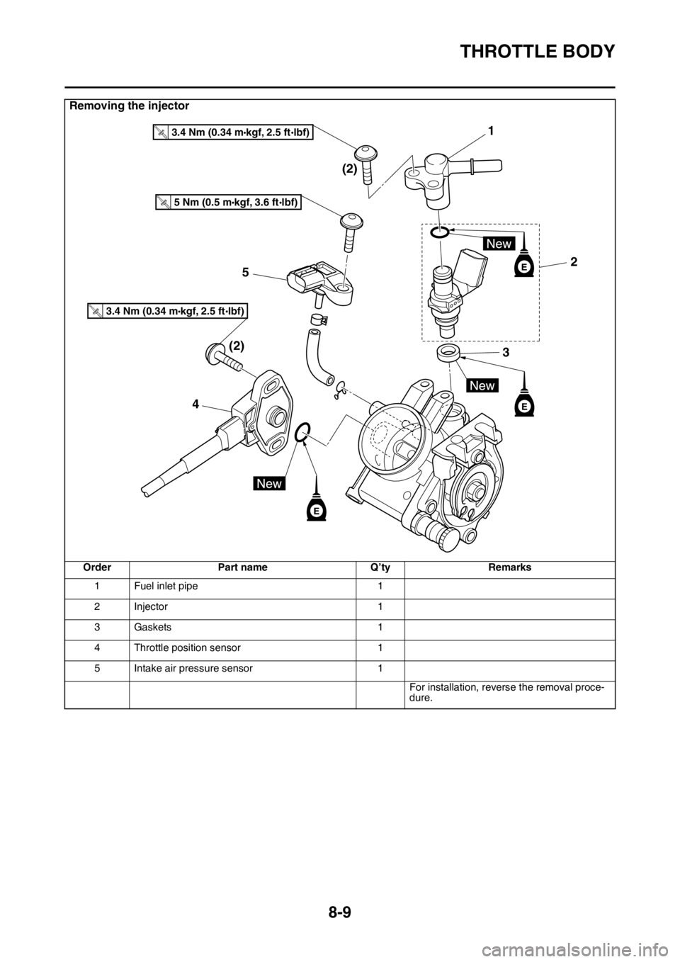
Removing the injector
Order Part name Q’ty Remarks
1 Fuel inlet pipe 1
2Injector 1
3 Gaskets 1
4 Throttle position sensor 1
5 Intake air pressure sensor 1
For installation, reverse the removal proce-
dure.
1
2 (2)
(2)5
43
T.R.3.4 Nm (0.34 mlbf) kgf, 2.5 ft
T.R.5 Nm (0.5 mlbf) kgf, 3.6 ft
T.R.3.4 Nm (0.34 mlbf) kgf, 2.5 ft
Page 333 of 432
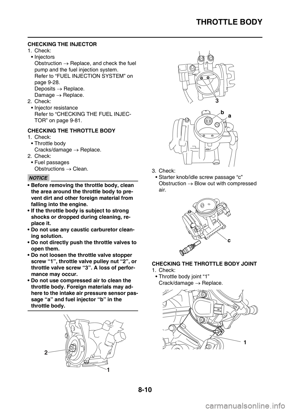
THROTTLE BODY
8-10
EAS2GBB352CHECKING THE INJECTOR
1. Check:
• Injectors
Obstruction Replace, and check the fuel
pump and the fuel injection system.
Refer to “FUEL INJECTION SYSTEM” on
page 9-28.
Deposits Replace.
Damage Replace.
2. Check:
• Injector resistance
Refer to “CHECKING THE FUEL INJEC-
TOR” on page 9-81.
EAS2GBB353CHECKING THE THROTTLE BODY
1. Check:
• Throttle body
Cracks/damage Replace.
2. Check:
• Fuel passages
Obstructions Clean.
ECA
NOTICE
• Before removing the throttle body, clean
the area around the throttle body to pre-
vent dirt and other foreign material from
falling into the engine.
• If the throttle body is subject to strong
shocks or dropped during cleaning, re-
place it.
• Do not use any caustic carburetor clean-
ing solution.
• Do not directly push the throttle valves to
open them.
• Do not loosen the throttle valve stopper
screw “1”, throttle valve pulley nut “2”, or
throttle valve screw “3”. A loss of perfor-
mance may occur.
• Do not use compressed air to clean the
throttle body. Foreign materials may ad-
here to the intake air pressure sensor pas-
sage “a” and fuel injector “b” in the
throttle body.3. Check:
• Starter knob/idle screw passage “c”
Obstruction Blow out with compressed
air.
EAS2GBB354CHECKING THE THROTTLE BODY JOINT
1. Check:
• Throttle body joint “1”
Crack/damage Replace.
1 2
3
ba
c
1
Page 334 of 432
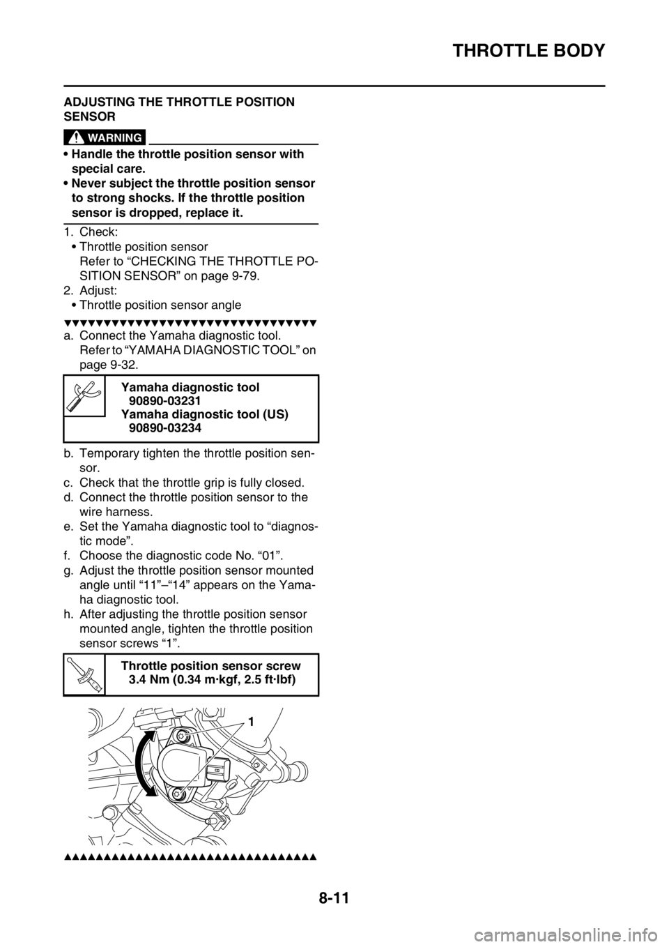
THROTTLE BODY
8-11
EAS2GBB355ADJUSTING THE THROTTLE POSITION
SENSOR
EWA
WARNING
• Handle the throttle position sensor with
special care.
• Never subject the throttle position sensor
to strong shocks. If the throttle position
sensor is dropped, replace it.
1. Check:
• Throttle position sensor
Refer to “CHECKING THE THROTTLE PO-
SITION SENSOR” on page 9-79.
2. Adjust:
• Throttle position sensor angle
▼▼▼▼▼▼▼▼▼▼▼▼▼▼▼▼▼▼▼▼▼▼▼▼▼▼▼▼▼▼▼▼
a. Connect the Yamaha diagnostic tool.
Refer to “YAMAHA DIAGNOSTIC TOOL” on
page 9-32.
b. Temporary tighten the throttle position sen-
sor.
c. Check that the throttle grip is fully closed.
d. Connect the throttle position sensor to the
wire harness.
e. Set the Yamaha diagnostic tool to “diagnos-
tic mode”.
f. Choose the diagnostic code No. “01”.
g. Adjust the throttle position sensor mounted
angle until “11”–“14” appears on the Yama-
ha diagnostic tool.
h. After adjusting the throttle position sensor
mounted angle, tighten the throttle position
sensor screws “1”.
▲▲▲▲▲▲▲▲▲▲▲▲▲▲▲▲▲▲▲▲▲▲▲▲▲▲▲▲▲▲▲▲
Yamaha diagnostic tool
90890-03231
Yamaha diagnostic tool (US)
90890-03234
Throttle position sensor screw
3.4 Nm (0.34 m·kgf, 2.5 ft·lbf)
T R..
1
Page 336 of 432

ELECTRICAL COMPONENTS....................................................................... 9-60
CHECKING THE SWITCHES .................................................................. 9-64
CHECKING THE BULBS AND BULB SOCKETS .................................... 9-67
CHECKING THE FUSES ......................................................................... 9-68
CHECKING AND CHARGING THE BATTERY ........................................ 9-69
CHECKING THE RELAYS ....................................................................... 9-72
CHECKING THE DIODE .......................................................................... 9-73
CHECKING THE IGNITION SPARK GAP................................................ 9-73
CHECKING THE SPARK PLUG CAP ...................................................... 9-74
CHECKING THE IGNITION COIL ............................................................ 9-74
CHECKING THE CRANKSHAFT POSITION SENSOR........................... 9-75
CHECKING THE LEAN ANGLE SENSOR............................................... 9-75
CHECKING THE STARTER MOTOR OPERATION ................................ 9-76
CHECKING THE STATOR COIL ............................................................. 9-76
CHECKING THE RECTIFIER/REGULATOR ........................................... 9-76
CHECKING THE SPEED SENSOR ......................................................... 9-77
CHECKING THE FUEL SENDER ............................................................ 9-77
CHECKING THE RESISTER ................................................................... 9-78
CHECKING THE RADIATOR FAN MOTOR ............................................ 9-78
CHECKING THE COOLANT TEMPERATURE SENSOR........................ 9-78
CHECKING THE THROTTLE POSITION SENSOR ................................ 9-79
CHECKING THE THROTTLE POSITION SENSOR INPUT VOLTAGE .. 9-80
CHECKING THE INTAKE AIR PRESSURE SENSOR ............................ 9-80
CHECKING THE INTAKE AIR TEMPERATURE SENSOR ..................... 9-80
CHECKING THE FUEL INJECTOR ......................................................... 9-81
Page 339 of 432

IGNITION SYSTEM
9-3
1. Joint connector
2. Joint connector
4. AC magneto
9. Battery
10.Frame ground
11.Starter relay
12.Main fuse
22.ECU (engine control unit)
23.Ignition coil
24.Spark plug
30.Joint connector
35.Lean angle sensor
36.Engine stop switch
48.Frame ground
49.Ignition coil sub-lead