ECU YAMAHA WR 250R 2011 Owners Manual
[x] Cancel search | Manufacturer: YAMAHA, Model Year: 2011, Model line: WR 250R, Model: YAMAHA WR 250R 2011Pages: 98, PDF Size: 2.57 MB
Page 10 of 98
1-3
SAFETY INFORMATION
1motorcycle can adversely affect stabili-
ty and handling if the weight distribution
of the motorcycle is changed. To avoid
the possibility of an accident, use ex-
treme caution when adding cargo or
accessories to your motorcycle. Use
extra care when riding a motorcycle
that has added cargo or accessories.
Here, along with the information about
accessories below, are some general
guidelines to follow if loading cargo to
your motorcycle:
The total weight of the operator, pas-
senger, accessories and cargo must
not exceed the maximum load limit.
Operation of an overloaded vehicle
could cause an accident.
When loading within this weight limit,
keep the following in mind:
Cargo and accessory weight
should be kept as low and close to
the motorcycle as possible. Se-
curely pack your heaviest items as
close to the center of the vehicle as
possible and make sure to distrib-ute the weight as evenly as possi-
ble on both sides of the motorcycle
to minimize imbalance or instabili-
ty.
Shifting weights can create a sud-
den imbalance. Make sure that ac-
cessories and cargo are securely
attached to the motorcycle before
riding. Check accessory mounts
and cargo restraints frequently.
• Properly adjust the suspension
for your load (suspension-ad-
justable models only), and
check the condition and pres-
sure of your tires.
• Never attach any large or heavy
items to the handlebar, front
fork, or front fender. These
items, including such cargo as
sleeping bags, duffel bags, or
tents, can create unstable han-
dling or a slow steering re-
sponse.
This vehicle is not designed to
pull a trailer or to be attached to
a sidecar.
Genuine Yamaha Accessories
Choosing accessories for your vehicleis an important decision. Genuine
Yamaha accessories, which are avail-
able only from a Yamaha dealer, have
been designed, tested, and approved
by Yamaha for use on your vehicle.
Many companies with no connection to
Yamaha manufacture parts and acces-
sories or offer other modifications for
Yamaha vehicles. Yamaha is not in a
position to test the products that these
aftermarket companies produce.
Therefore, Yamaha can neither en-
dorse nor recommend the use of ac-
cessories not sold by Yamaha or
modifications not specifically recom-
mended by Yamaha, even if sold and
installed by a Yamaha dealer.
Aftermarket Parts, Accessories,
and Modifications
While you may find aftermarket prod-
ucts similar in design and quality to
genuine Yamaha accessories, recog-
nize that some aftermarket accessories
or modifications are not suitable be-
cause of potential safety hazards to you
or others. Installing aftermarket prod-
ucts or having other modifications per-
formed to your vehicle that change any
Maximum load:
185 kg (408 lb)
32D-9-E6.book 3 ページ 2011年1月7日 金曜日 午後3時10分
Page 11 of 98
1-4
1
SAFETY INFORMATION
of the vehicle’s design or operation
characteristics can put you and others
at greater risk of serious injury or death.
You are responsible for injuries related
to changes in the vehicle.
Keep the following guidelines in mind,
as well as those provided under “Load-
ing” when mounting accessories.
Never install accessories or carry
cargo that would impair the perfor-
mance of your motorcycle. Care-
fully inspect the accessory before
using it to make sure that it does
not in any way reduce ground
clearance or cornering clearance,
limit suspension travel, steering
travel or control operation, or ob-
scure lights or reflectors.
• Accessories fitted to the handle-
bar or the front fork area can
create instability due to improper
weight distribution or aerody-
namic changes. If accessories
are added to the handlebar or
front fork area, they must be as
lightweight as possible and
should be kept to a minimum.
• Bulky or large accessories may
seriously affect the stability ofthe motorcycle due to aerody-
namic effects. Wind may at-
tempt to lift the motorcycle, or
the motorcycle may become un-
stable in cross winds. These ac-
cessories may also cause
instability when passing or being
passed by large vehicles.
• Certain accessories can dis-
place the operator from his or
her normal riding position. This
improper position limits the free-
dom of movement of the opera-
tor and may limit control ability,
therefore, such accessories are
not recommended.
Use caution when adding electri-
cal accessories. If electrical acces-
sories exceed the capacity of the
motorcycle’s electrical system, an
electric failure could result, which
could cause a dangerous loss of
lights or engine power.
Aftermarket Tires and Rims
The tires and rims that came with your
motorcycle were designed to match the
performance capabilities and to provide
the best combination of handling, brak-ing, and comfort. Other tires, rims, siz-
es, and combinations may not be
appropriate. Refer to page 6-20 for tire
specifications and more information on
replacing your tires.
Transporting the Motorcycle
Be sure to observe following instruc-
tions before transporting the motorcy-
cle in another vehicle.
Remove all loose items from the
motorcycle.
Check that the fuel cock (if
equipped) is in the “OFF” position
and that there are no fuel leaks.
Point the front wheel straight
ahead on the trailer or in the truck
bed, and choke it in a rail to pre-
vent movement.
Shift the transmission in gear (for
models with a manual transmis-
sion).
Secure the motorcycle with
tie-downs or suitable straps that
are attached to solid parts of the
motorcycle, such as the frame or
upper front fork triple clamp (and
not, for example, to rubber-mount-
ed handlebars or turn signals, or
32D-9-E6.book 4 ページ 2011年1月7日 金曜日 午後3時10分
Page 27 of 98
INSTRUMENT AND CONTROL FUNCTIONS
3-12
234
5
6
7
8
9 3. Wipe up any spilled fuel immedi-
ately. NOTICE: Immediately wipe
off spilled fuel with a clean, dry,
soft cloth, since fuel may deteri-
orate painted surfaces or plastic
parts.
[ECA10071]
4. Be sure to securely close the fuel
tank cap.
WARNING
EWA15151
Gasoline is poisonous and can
cause injury or death. Handle gaso-
line with care. Never siphon gaso-
line by mouth. If you should swallow
some gasoline or inhale a lot of gas-
oline vapor, or get some gasoline inyour eyes, see your doctor immedi-
ately. If gasoline spills on your skin,
wash with soap and water. If gaso-
line spills on your clothing, change
your clothes.
EAU13391
NOTICE
ECA11400
Use only unleaded gasoline. The use
of leaded gasoline will cause severe
damage to internal engine parts,
such as the valves and piston rings,as well as to the exhaust system.
Your Yamaha engine has been de-
signed to use premium unleaded gaso-
line with a research octane number of
95 or higher. If knocking (or pinging) oc-
curs, use a gasoline of a different
brand. Use of unleaded fuel will extendspark plug life and reduce maintenance
costs.
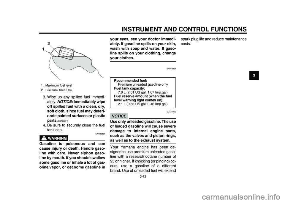
1. Maximum fuel level
2. Fuel tank filler tube
2
1
Recommended fuel:
Premium unleaded gasoline only
Fuel tank capacity:
7.6 L (2.01 US gal, 1.67 Imp.gal)
Fuel reserve amount (when the fuel
level warning light comes on):
2.1 L (0.55 US gal, 0.46 Imp.gal)
32D-9-E6.book 12 ページ 2011年1月7日 金曜日 午後3時10分
Page 71 of 98
PERIODIC MAINTENANCE AND ADJUSTMENT
6-29
2
3
4
567
8
9
EAU23095
Checking and lubricating the
cables The operation of all control cables and
the condition of the cables should be
checked before each ride, and the ca-
bles and cable ends should be lubricat-
ed if necessary. If a cable is damaged
or does not move smoothly, have a
Yamaha dealer check or replace it.
WARNING! Damage to the outer
housing of cables may result in in-
ternal rusting and cause interfer-
ence with cable movement. Replace
damaged cables as soon as possi-
ble to prevent unsafe condi-
tions.
[EWA10711]
EAU23114
Checking and lubricating the
throttle grip and cable The operation of the throttle grip should
be checked before each ride. In addi-
tion, the cable should be lubricated by a
Yamaha dealer at the intervals speci-
fied in the periodic maintenance chart.
The throttle cable is equipped with a
rubber cover. Make sure that the cover
is securely installed. Even though the
cover is installed correctly, it does not
completely protect the cable from water
entry. Therefore, use care not to pour
water directly onto the cover or cable
when washing the vehicle. If the cable
or cover becomes dirty, wipe clean with
a moist cloth.
EAU23142
Checking and lubricating the
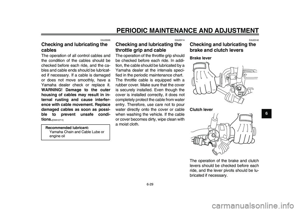
brake and clutch levers Brake lever
Clutch lever
The operation of the brake and clutch
levers should be checked before each
ride, and the lever pivots should be lu-
bricated if necessary.
Recommended lubricant:
Yamaha Chain and Cable Lube or
engine oil
32D-9-E6.book 29 ページ 2011年1月7日 金曜日 午後3時10分
Page 73 of 98
PERIODIC MAINTENANCE AND ADJUSTMENT
6-31
2
3
4
567
8
9
EAUM1651
Lubricating the swingarm
pivots The swingarm pivots must be lubricat-
ed by a Yamaha dealer at the intervals
specified in the periodic maintenance
and lubrication chart.
EAU23272
Checking the front fork The condition and operation of the front
fork must be checked as follows at the
intervals specified in the periodic main-
tenance and lubrication chart.
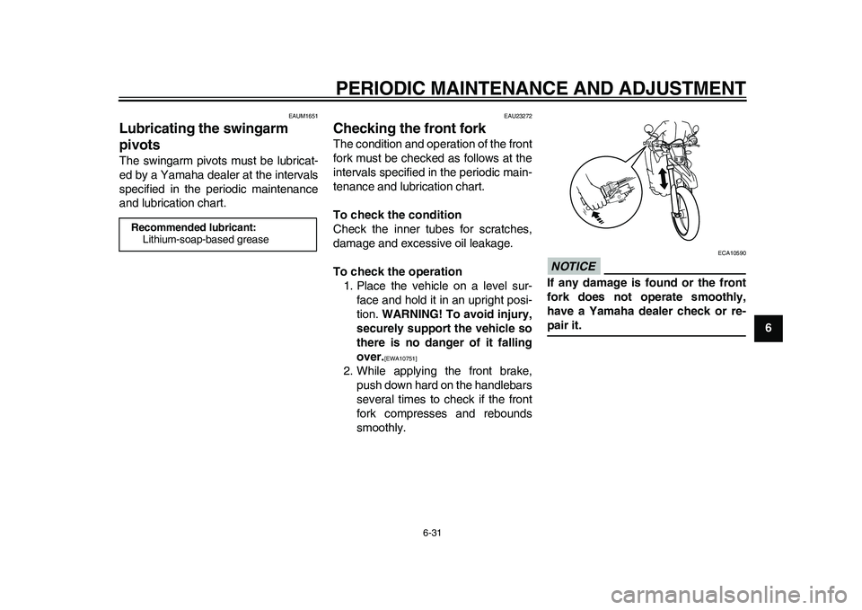
To check the condition
Check the inner tubes for scratches,
damage and excessive oil leakage.
To check the operation
1. Place the vehicle on a level sur-
face and hold it in an upright posi-
tion. WARNING! To avoid injury,
securely support the vehicle so
there is no danger of it falling
over.
[EWA10751]
2. While applying the front brake,
push down hard on the handlebars
several times to check if the front
fork compresses and rebounds
smoothly.
NOTICE
ECA10590
If any damage is found or the front
fork does not operate smoothly,
have a Yamaha dealer check or re-pair it.
Recommended lubricant:
Lithium-soap-based grease
32D-9-E6.book 31 ページ 2011年1月7日 金曜日 午後3時10分
Page 74 of 98
PERIODIC MAINTENANCE AND ADJUSTMENT
6-32
1
2
3
4
56
7
8
9
EAU23283
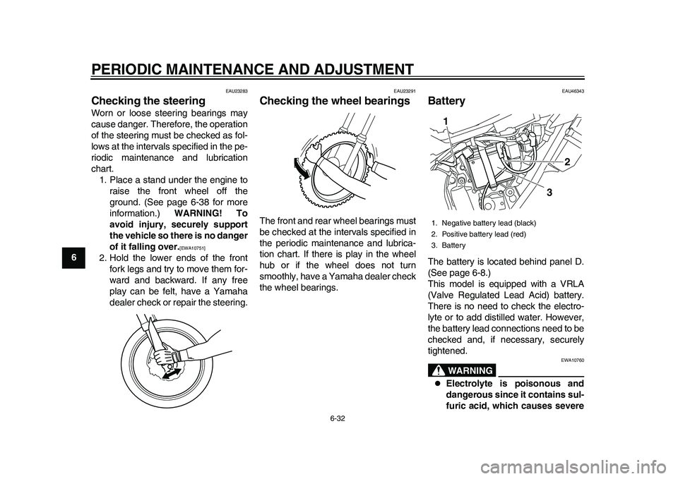
Checking the steering Worn or loose steering bearings may
cause danger. Therefore, the operation
of the steering must be checked as fol-
lows at the intervals specified in the pe-
riodic maintenance and lubrication
chart.
1. Place a stand under the engine to
raise the front wheel off the
ground. (See page 6-38 for more
information.) WARNING! To
avoid injury, securely support
the vehicle so there is no danger
of it falling over.
[EWA10751]
2. Hold the lower ends of the front
fork legs and try to move them for-
ward and backward. If any free
play can be felt, have a Yamaha
dealer check or repair the steering.
EAU23291
Checking the wheel bearings The front and rear wheel bearings must
be checked at the intervals specified in
the periodic maintenance and lubrica-
tion chart. If there is play in the wheel
hub or if the wheel does not turn
smoothly, have a Yamaha dealer check
the wheel bearings.
EAU46343
Battery The battery is located behind panel D.
(See page 6-8.)
This model is equipped with a VRLA
(Valve Regulated Lead Acid) battery.
There is no need to check the electro-
lyte or to add distilled water. However,
the battery lead connections need to be
checked and, if necessary, securely
tightened.
WARNING
EWA10760
Electrolyte is poisonous and
dangerous since it contains sul-
furic acid, which causes severe
1. Negative battery lead (black)
2. Positive battery lead (red)
3. Battery
3
2
1
32D-9-E6.book 32 ページ 2011年1月7日 金曜日 午後3時10分
Page 78 of 98
PERIODIC MAINTENANCE AND ADJUSTMENT
6-36
1
2
3
4
56
7
8
9sition, and then secure it with the
bulb holder.
5. Install the bulb cover, and then
connect the coupler.
6. Install the headlight cowling (to-
gether with the headlight unit) by
placing it in the original position,
and then installing the bolts.
7. Have a Yamaha dealer adjust the
headlight beam if necessary.
EAU24181
Tail/brake light This model is equipped with an
LED-type tail/brake light.
If the tail/brake light does not come on,
have a Yamaha dealer check it.
EAU24204
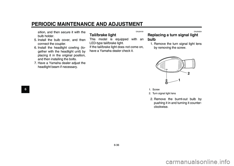
Replacing a turn signal light
bulb 1. Remove the turn signal light lens
by removing the screw.
2. Remove the burnt-out bulb by
pushing it in and turning it counter-
clockwise.1. Screw
2. Turn signal light lens
1
2
32D-9-E6.book 36 ページ 2011年1月7日 金曜日 午後3時10分
Page 81 of 98
PERIODIC MAINTENANCE AND ADJUSTMENT
6-39
2
3
4
567
8
9
EAU24360
Front wheel
EAU49331
To remove the front wheel
WARNING
EWA10821
To avoid injury, securely support the
vehicle so there is no danger of itfalling over.
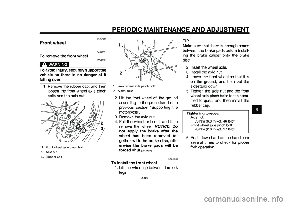
1. Remove the rubber cap, and then
loosen the front wheel axle pinch
bolts and the axle nut.
2. Lift the front wheel off the ground
according to the procedure in the
previous section “Supporting the
motorcycle”.
3. Remove the axle nut.
4. Pull the wheel axle out, and then
remove the wheel. NOTICE: Do
not apply the brake after the
wheel has been removed to-
gether with the brake disc, oth-
erwise the brake pads will be
forced shut.
[ECA11071]
EAU49341
To install the front wheel
1. Lift the wheel up between the fork
legs.
TIPMake sure that there is enough space
between the brake pads before install-
ing the brake caliper onto the brakedisc.
2. Insert the wheel axle.
3. Install the axle nut.
4. Lower the front wheel so that it is
on the ground, and then put the
sidestand down.
5. Tighten the axle nut and the front
wheel axle pinch bolts to the spec-
ified torques, and then install the
rubber cap.
6. Push down hard on the handlebar
several times to check for proper
fork operation.
1. Front wheel axle pinch bolt
2. Axle nut
3. Rubber cap
23
1
1. Front wheel axle pinch bolt
2. Wheel axle
1
2
Tightening torques:
Axle nut:
63 Nm (6.3 m·kgf, 46 ft·lbf)
Front wheel axle pinch bolt:
23 Nm (2.3 m·kgf, 17 ft·lbf)
32D-9-E6.book 39 ページ 2011年1月7日 金曜日 午後3時10分
Page 82 of 98
PERIODIC MAINTENANCE AND ADJUSTMENT
6-40
1
2
3
4
56
7
8
9
EAU25080
Rear wheel
EAU45182
To remove the rear wheel
WARNING
EWA10821
To avoid injury, securely support the
vehicle so there is no danger of itfalling over.
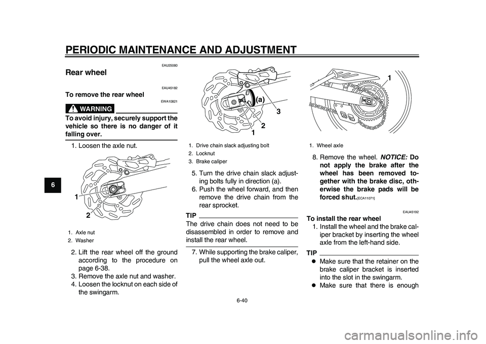
1. Loosen the axle nut.
2. Lift the rear wheel off the ground
according to the procedure on
page 6-38.
3. Remove the axle nut and washer.
4. Loosen the locknut on each side of
the swingarm.5. Turn the drive chain slack adjust-
ing bolts fully in direction (a).
6. Push the wheel forward, and then
remove the drive chain from the
rear sprocket.
TIPThe drive chain does not need to be
disassembled in order to remove andinstall the rear wheel.
7. While supporting the brake caliper,
pull the wheel axle out.8. Remove the wheel. NOTICE: Do
not apply the brake after the
wheel has been removed to-
gether with the brake disc, oth-
erwise the brake pads will be
forced shut.
[ECA11071]
EAU45192
To install the rear wheel
1. Install the wheel and the brake cal-
iper bracket by inserting the wheel
axle from the left-hand side.TIP
Make sure that the retainer on the
brake caliper bracket is inserted
into the slot in the swingarm.
Make sure that there is enough
1. Axle nut
2. Washer1
2
1. Drive chain slack adjusting bolt
2. Locknut
3. Brake caliper
12
3 (a)
1. Wheel axle
1
32D-9-E6.book 40 ページ 2011年1月7日 金曜日 午後3時10分