oil level YAMAHA WR 250R 2016 Owners Manual
[x] Cancel search | Manufacturer: YAMAHA, Model Year: 2016, Model line: WR 250R, Model: YAMAHA WR 250R 2016Pages: 100, PDF Size: 2.65 MB
Page 6 of 100

Table of contentsSafety information............................ 1-1
Description ........................................ 2-1
Left view .......................................... 2-1
Right view ........................................ 2-2
Controls and instrument s................. 2-3
Instrument and co ntrol functions.... 3-1
Main switch/steering lock................. 3-1
Indicator lights and warning lights ... 3-2
Multi-function display ....................... 3-3
Handlebar switches ......................... 3-8
Clutch lever...................................... 3-9
Shift pedal....... ............................. .. 3-10
Brake lever .................................... 3-10
Brake pedal ................................... 3-10
Fuel tank cap ................................. 3-11
Fuel................................................ 3-11
Catalytic converter ......................... 3-13
Seat ............................................... 3-13
Helmet holder ................................ 3-14
Adjusting the front fork................... 3-14
Front fork bleeding......................... 3-16
Adjusting the shock absorber assembly .................................... 3-17
EXUP system ................................ 3-18
Sidestand....................................... 3-19
Ignition circuit cut-of f system ......... 3-19
For your safety –
pre-operation checks ........................ 4-1Operation and important riding
points
................................................. 5-1
Starting the engine .......................... 5-1
Shifting ............................................ 5-2
Tips for reducing fuel consumption ................................ 5-3
Engine break-in ............................... 5-3
Parking ............................................ 5-4
Periodic maintenance and
adjustment ........................................ 6-1
Owner’s tool kit................................ 6-2
Periodic maintenance chart for the emission contro l system ........ 6-3
General maintenance and lubrication chart ........................... 6-4
Removing and installing panels ...... 6-8
Checking the spark plug................ 6-11
Engine oil and oil filter element ..... 6-12
Coolant .......................................... 6-14
Cleaning the air filter element and check hose.......................... 6-17
Adjusting the engine idling
speed ......................................... 6-19
Checking the throttle grip free
play ............................................ 6-19
Valve clearance............................. 6-20
Tires .............................................. 6-20
Spoke wheels .............. .................. 6-22
Adjusting the clutch lever free play ............................................ 6-22 Adjusting the brake lever free
play ............................................. 6-23
Checking the shift pedal ................ 6-24
Brake light switches ....................... 6-25
Checking the front and rear brake pads.................................. 6-25
Checking the brake fluid level ........ 6-26
Changing the brake fluid ................ 6-27
Drive chain slack............................ 6-27
Cleaning and lubricating the drive chain .................................. 6-28
Checking and lubricating the cables ......................................... 6-29
Checking and lubricating the
throttle grip and cable ................. 6-29
Checking and lubricating the brake and clutch levers .............. 6-30
Checking and lubricating the brake pedal................................. 6-30
Checking and lubricating the
sidestand .................................... 6-31
Lubricating the swingarm pivots .... 6-31
Checking the front fork................... 6-31
Checking the steering .................... 6-32
Checking the wheel bearings......... 6-32
Battery ........................................... 6-33
Replacing the fuses ....................... 6-34
Replacing the headlight bulb ......... 6-35
Replacing the auxiliary light bulb ............................................ 6-36
Tail/brake light ............................... 6-36BN3-9-E0.book 1 ページ 2015年6月25日 木曜日 午前10時46分
Page 14 of 100

Description
2-2
12
3
4
5
6
7
8
9
10
11
12
EAU10421
Right view
3
1
2
9 7
6
5
8
4
1. Rear brake fluid reservoir (page 6-26)
2. Air filter element (page 6-17)
3. Rear brake light switch (page 6-25)
4. Fuel tank cap (page 3-11)
5. Bleed screw (page 3-16)
6. Engine oil filler cap (page 6-12)
7. Engine oil level check window (page 6-12)
8. Brake pedal (page 3-10) 9. Shock absorber assembly r
ebound damping force adjusting knob
(page 3-17)
BN3-9-E0.book 2 ページ 2015年6月25日 木曜日 午前10時46分
Page 36 of 100
4-1
1
2
34
5
6
7
8
9
10
11
12
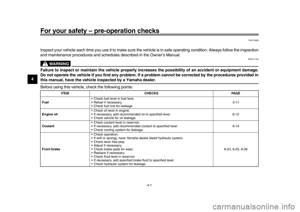
For your safety – pre-operation checks
EAU15599
Inspect your vehicle each time you use it to make sure the vehi cle is in safe operating condition. Always follow the inspection
and maintenance procedures and schedules described in the Owner’s Manual.
WARNING
EWA11152
Failure to inspect or maintain the vehicle properly increases the possibility of an accident or equipment damage.
Do not operate the vehicle if you find any problem. If a problem cannot be corrected by the procedures provided inthis manual, have the vehicle inspected by a Yamaha dealer.
Before using this vehicle, check the following points:
ITEM CHECKS PAGE
Fuel Check fuel level in fuel tank.
Refuel if necessary.
Check fuel line for leakage. 3-11
Engine oil Check oil level in engine.
If necessary, add recommended oil to specified level.
Check vehicle for oil leakage. 6-12
Coolant Check coolant level in reservoir.
If necessary, add recommended coolant to specified level.
Check cooling system for leakage. 6-14
Front brake Check operation.
If soft or spongy, have Yamaha dealer bleed hydraulic system.
Check lever free play.
Adjust if necessary.
Check brake pads for wear.
Replace if necessary.
Check fluid level in reservoir.
If necessary, add specified brake fluid to specified level.
Check hydraulic system for leakage. 6-23, 6-25, 6-26
BN3-9-E0.book 1 ページ 2015年6月25日 木曜日 午前10時46分
Page 48 of 100

Periodic maintenance and adjustment
6-6
1
2
3
4
56
7
8
9
10
11
12
21 *Rear suspension
relay arm and
connecting arm
pivoting points Check operation.
22 Engine oil Change.
Check oil level and vehicle for oil
leakage.
Every 5000 km (3000 mi)
23 Engine oil filter
element
24 *Cooling system Check coolant level and vehicle
for coolant leakage.
Change coolant. Every 3 years
25 *Front and rear brake
switches Check operation.
26 Moving parts and
cables Lubricate.
27 *Throttle grip Check operation.
Check throttle grip free play, and
adjust if necessary.
Lubricate cable and grip housing.
28 *Lights, signals and
switches Check operation.
Adjust headlight beam.
NO. ITEM CHECK OR MAINTENANCE JOB
ODOMETER READING
ANNUAL
CHECK
1000 km
(600 mi) 10000 km
(6000 mi) 20000 km
(12000 mi) 30000 km
(18000 mi) 40000 km
(24000 mi)BN3-9-E0.book 6 ページ 2015年6月25日 木曜日 午前10時46分
Page 54 of 100

Periodic maintenance and adjustment
6-12
1
2
3
4
56
7
8
9
10
11
12
EAU45145
Engine oil and oil filter
elementThe engine oil level should be checked
before each ride. In addition, the oil
must be changed and the oil filter ele-
ment replaced at the intervals specified
in the periodic maintenance and lubri-
cation chart.
To check the engine oil level 1. Place the vehicle on a level sur- face and hold it in an upright posi-
tion. A slight tilt to the side can
result in a false reading.
2. Start the engine, warm it up for several minutes, and then turn it
off.
3. Wait a few minutes until the oil set- tles, and then check the oil level
through the check window located
at the bottom-right side of the
crankcase.TIPThe engine oil should be between theminimum and maximum level marks. 4. If the engine oil is below the mini-
mum level mark, add sufficient oil
of the recommended type to raise
it to the correct level.
To change the engine oil (with or
without oil filter element replace-
ment) 1. Place the vehicle on a level sur- face.
2. Start the engine, warm it up for several minutes, and then turn it
off.
3. Place an oil pan under the engine to collect the used oil.
4. Remove the engine oil filler cap, the engine oil drain bolt and its
gasket to drain the oil from the
crankcase.
TIPSkip steps 5–8 if the oil filter element isnot being replaced.
5. Remove the oil filter element cover by removing the bolts.
1. Engine oil filler cap
2. Maximum level mark
3. Minimum level mark
4. Engine oil level check window
1
2
3 4
1. Engine oil drain bolt
2. Gasket
12
BN3-9-E0.book 12 ページ 2015年6月25日 木曜日 午前10時46分
Page 55 of 100

Periodic maintenance and adjustment6-13
1
2
3
4
567
8
9
10
11
12
6. Remove the oil filter element and
O-rings.
7. Install a new oil filter element and new O-rings.
TIPMake sure that the O-rings are properlyseated.
8. Install the oil filter element cover by installing the bolts, then tightening
them to the specified torque.
9. Install the engine oil drain bolt and its new gasket, and then tighten
the bolt to the specified torque.
10. Refill with the specified amount of the recommended engine oil, and
then install and tighten the oil filler
cap.
TIPBe sure to wipe off spilled oil on any
parts after the engine and exhaust sys-tem have cooled down.NOTICE
ECA11621
In order to prevent clutch slip-
page (since the engine oil also
lubricates the clutch), do not
mix any chemical additives. Do
not use oils with a diesel speci-
fication of “CD” or oils of a high-
er quality than specified. In
addition, do not use oils labeled
“ENERGY CONSERVING II” or
higher.
Make sure that no foreign mate-rial enters the crankcase.
11. Start the engine, and then let it idle for several minutes while checking
it for oil leakage. If oil is leaking, im-
mediately turn the engine off and
check for the cause.
12. Turn the engine off, wait a few min- utes until the oil settles, and then
check the oil level and correct it if
necessary.
1. Oil filter element cover
2. Oil filter element cover bolt
1. O-ring
2. Oil filter element
1
2
1
2
Tightening torque:Oil filter element cover bolt:
10 Nm (1.0 m·kgf, 7.2 ft·lbf)
Tightening torque: Engine oil drain bolt:20 Nm (2.0 m·kgf, 14 ft·lbf)
Recommended oil: See page 8-1.
Oil quantity: Oil change:
1.30 L (1.37 US qt, 1.14 Imp.qt)
With oil filter removal: 1.40 L (1.48 US qt, 1.23 Imp.qt)
BN3-9-E0.book 13 ページ 2015年6月25日 木曜日 午前10時46分
Page 56 of 100
Periodic maintenance and adjustment
6-14
1
2
3
4
56
7
8
9
10
11
12
NOTICE
ECA11232
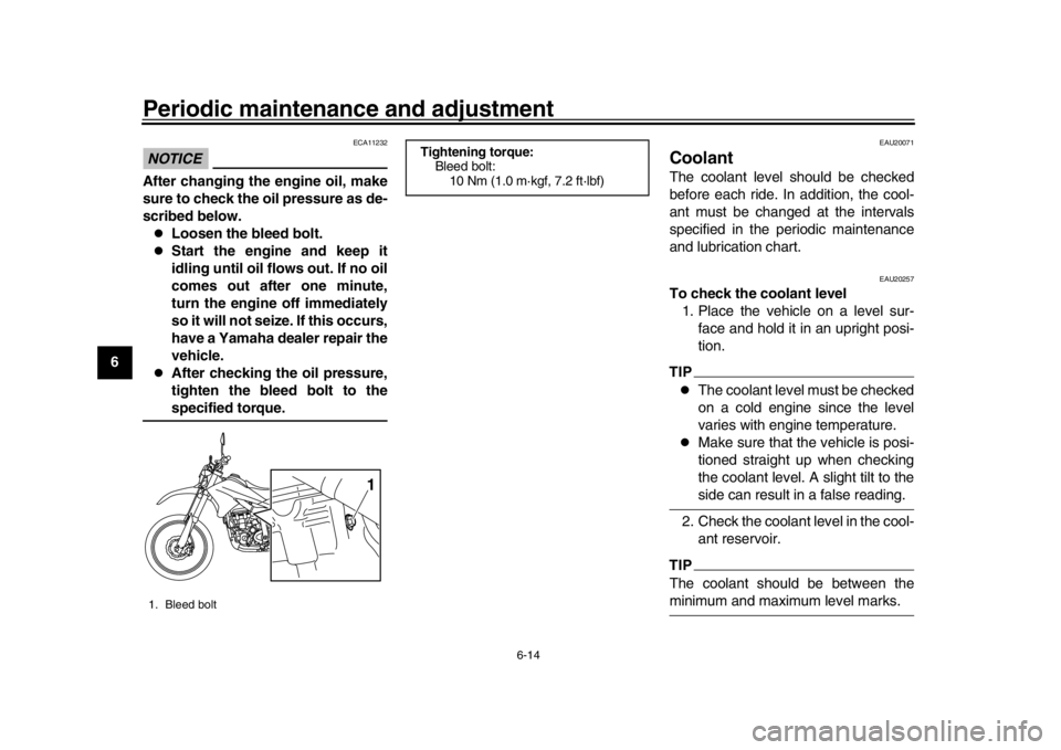
After changing the engine oil, make
sure to check the oil pressure as de-
scribed below.
Loosen the bleed bolt.
Start the engine and keep it
idling until oil flows out. If no oil
comes out after one minute,
turn the engine off immediately
so it will not seize. If this occurs,
have a Yamaha dealer repair the
vehicle.
After checking the oil pressure,
tighten the bleed bolt to thespecified torque.
EAU20071
CoolantThe coolant level should be checked
before each ride. In addition, the cool-
ant must be changed at the intervals
specified in the periodic maintenance
and lubrication chart.
EAU20257
To check the coolant level 1. Place the vehicle on a level sur- face and hold it in an upright posi-
tion.TIP
The coolant level must be checked
on a cold engine since the level
varies with engine temperature.
Make sure that the vehicle is posi-
tioned straight up when checking
the coolant level. A slight tilt to theside can result in a false reading.
2. Check the coolant level in the cool- ant reservoir.
TIPThe coolant should be between theminimum and maximum level marks.
1. Bleed bolt
1
Tightening torque:Bleed bolt:10 Nm (1.0 m·kgf, 7.2 ft·lbf)
BN3-9-E0.book 14 ページ 2015年6月25日 木曜日 午前10時46分
Page 68 of 100
Periodic maintenance and adjustment
6-26
1
2
3
4
56
7
8
9
10
11
12
EAU22582
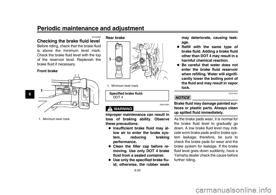
Checking the brake fluid levelBefore riding, check that the brake fluid
is above the minimum level mark.
Check the brake fluid level with the top
of the reservoir level. Replenish the
brake fluid if necessary.
Front brake Rear brake
WARNING
EWA15991
Improper maintenance can result in
loss of braking ability. Observe
these precautions:
Insufficient brake fluid may al-
low air to enter the brake sys-
tem, reducing braking
performance.
Clean the filler cap before re-
moving. Use only DOT 4 brake
fluid from a sealed container.
Use only the specified brake flu-
id; otherwise, the rubber sealsmay deteriorate, causing leak-
age.
Refill with the same type of
brake fluid. Adding a brake fluid
other than DOT 4 may result in a
harmful chemical reaction.
Be careful that water does not
enter the brake fluid reservoir
when refilling. Water will signifi-
cantly lower the boiling point of
the fluid and may result in vaporlock.
NOTICE
ECA17641
Brake fluid may damage painted sur-
faces or plastic parts. Always cleanup spilled fluid immediately.
As the brake pads wear, it is normal for
the brake fluid level to gradually go
down. A low brake fluid level may indi-
cate worn brake pads and/or brake sys-
tem leakage; therefore, be sure to
check the brake pads for wear and the
brake system for leakage. If the brake
fluid level goes down suddenly, have a
Yamaha dealer check the cause before
further riding.
1. Minimum level mark1
1. Minimum level markSpecified brake fluid:
DOT 41
BN3-9-E0.book 26 ページ 2015年6月25日 木曜日 午前10時46分
Page 73 of 100
Periodic maintenance and adjustment6-31
1
2
3
4
567
8
9
10
11
12
EAU23203
Checking and lubricating the
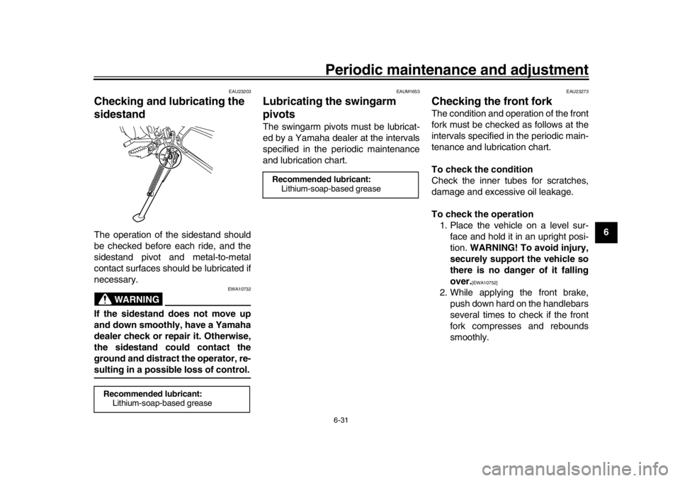
sidestandThe operation of the sidestand should
be checked before each ride, and the
sidestand pivot and metal-to-metal
contact surfaces should be lubricated if
necessary.
WARNING
EWA10732
If the sidestand does not move up
and down smoothly, have a Yamaha
dealer check or repair it. Otherwise,
the sidestand could contact the
ground and distract the operator, re-sulting in a possible loss of control.
EAUM1653
Lubricating the swingarm
pivotsThe swingarm pivots must be lubricat-
ed by a Yamaha dealer at the intervals
specified in the periodic maintenance
and lubrication chart.
EAU23273
Checking the front forkThe condition and operation of the front
fork must be checked as follows at the
intervals specified in the periodic main-
tenance and lubrication chart.
To check the condition
Check the inner tubes for scratches,
damage and excessive oil leakage.
To check the operation 1. Place the vehicle on a level sur- face and hold it in an upright posi-
tion. WARNING! To avoid injury,
securely support the vehicle so
there is no danger of it falling
over.
[EWA10752]
2. While applying the front brake, push down hard on the handlebars
several times to check if the front
fork compresses and rebounds
smoothly.
Recommended lubricant:Lithium-soap-based grease
Recommended lubricant:
Lithium-soap-based grease
BN3-9-E0.book 31 ページ 2015年6月25日 木曜日 午前10時46分
Page 91 of 100
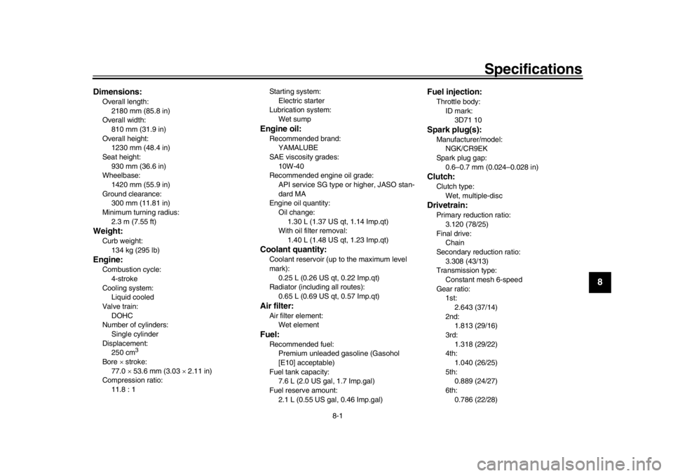
8-1
1
2
3
4
5
6
789
10
11
12
Specifications
EAU69993
Dimensions:Overall length: 2180 mm (85.8 in)
Overall width: 810 mm (31.9 in)
Overall height: 1230 mm (48.4 in)
Seat height:
930 mm (36.6 in)
Wheelbase: 1420 mm (55.9 in)
Ground clearance: 300 mm (11.81 in)
Minimum turning radius:
2.3 m (7.55 ft)Weight:Curb weight:134 kg (295 lb)Engine:Combustion cycle:4-stroke
Cooling system: Liquid cooled
Valve train:
DOHC
Number of cylinders: Single cylinder
Displacement: 250 cm
3
Bore stroke:
77.0 53.6 mm (3.03 2.11 in)
Compression ratio: 11.8 : 1 Starting system:
Electric starter
Lubrication system:
Wet sump
Engine oil:Recommended brand:YAMALUBE
SAE viscosity grades:
10W-40
Recommended engine oil grade: API service SG type or higher, JASO stan-
dard MA
Engine oil quantity: Oil change:
1.30 L (1.37 US qt, 1.14 Imp.qt)
With oil filter removal: 1.40 L (1.48 US qt, 1.23 Imp.qt)Coolant quantity:Coolant reservoir (up to the maximum level
mark): 0.25 L (0.26 US qt, 0.22 Imp.qt)
Radiator (including all routes):
0.65 L (0.69 US qt, 0.57 Imp.qt)Air filter:Air filter element:Wet elementFuel:Recommended fuel:Premium unleaded gasoline (Gasohol
[E10] acceptable)
Fuel tank capacity: 7.6 L (2.0 US gal, 1.7 Imp.gal)
Fuel reserve amount: 2.1 L (0.55 US gal, 0.46 Imp.gal)
Fuel injection:Throttle body:ID mark:3D71 10Spark plug(s):Manufacturer/model: NGK/CR9EK
Spark plug gap: 0.6–0.7 mm (0.024–0.028 in)Clutch:Clutch type:Wet, multiple-discDrivetrain:Primary reduction ratio:
3.120 (78/25)
Final drive: Chain
Secondary reduction ratio: 3.308 (43/13)
Transmission type:
Constant mesh 6-speed
Gear ratio: 1st:
2.643 (37/14)
2nd: 1.813 (29/16)
3rd: 1.318 (29/22)
4th:
1.040 (26/25)
5th: 0.889 (24/27)
6th: 0.786 (22/28)
BN3-9-E0.book 1 ページ 2015年6月25日 木曜日 午前10時46分