brake YAMAHA WR 400F 2000 Betriebsanleitungen (in German)
[x] Cancel search | Manufacturer: YAMAHA, Model Year: 2000, Model line: WR 400F, Model: YAMAHA WR 400F 2000Pages: 654, PDF-Größe: 60.12 MB
Page 226 of 654
3 - 31
INSP
ADJREAR BRAKE PAD INSULATOR INSPECTION/
BRAKE FLUID LEVEL INSPECTION
3. Inspect:
lBrake fluid level
Refer to “BRAKE FLUID LEVEL
INSPECTION” section.
4. Check:
lBrake pedal operation
A softy or spongy feeling ® Bleed
brake system.
Refer to “BRAKE SYSTEM AIR
BLEEDING” section.
EC36b000
REAR BRAKE PAD INSULATOR
INSPECTION
1. Remove:
lBrake pad
Refer to “REAR BRAKE PAD INSPEC-
TION AND REPLACEMENT” section.
2. Inspect:
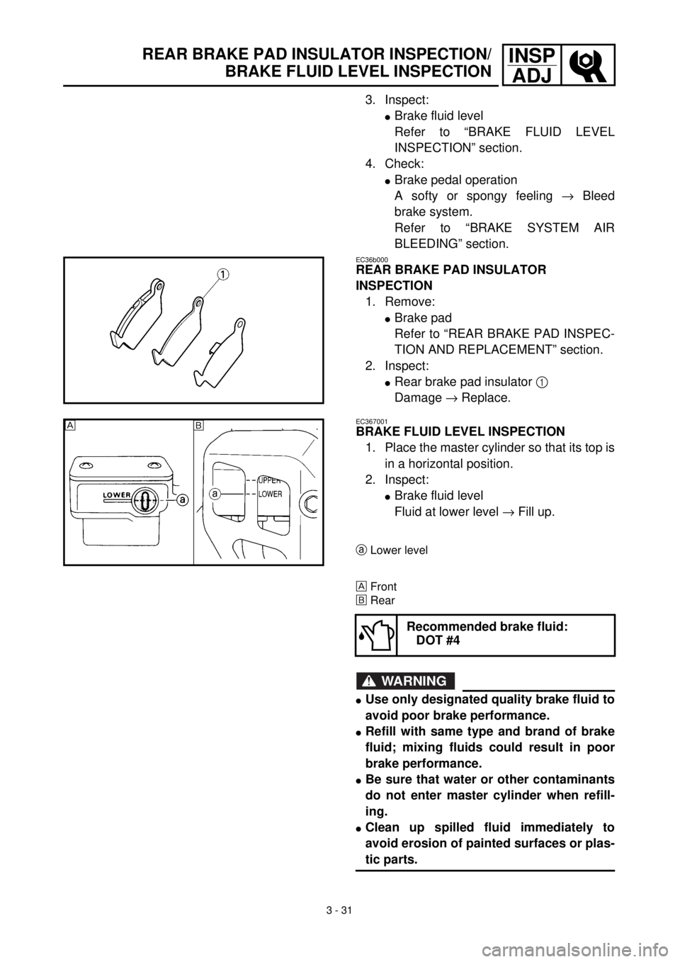
lRear brake pad insulator 1
Damage ® Replace.
EC367001
BRAKE FLUID LEVEL INSPECTION
1. Place the master cylinder so that its top is
in a horizontal position.
2. Inspect:
lBrake fluid level
Fluid at lower level ® Fill up.
aLower level
Front
õRear
WARNING
lUse only designated quality brake fluid to
avoid poor brake performance.
lRefill with same type and brand of brake
fluid; mixing fluids could result in poor
brake performance.
lBe sure that water or other contaminants
do not enter master cylinder when refill-
ing.
lClean up spilled fluid immediately to
avoid erosion of painted surfaces or plas-
tic parts.
Recommended brake fluid:
DOT #4
õ
Page 232 of 654
3 - 34
INSP
ADJ
FRONT FORK INSPECTION
3. Adjust:
lDrive chain slack
Drive chain slack adjustment steps:
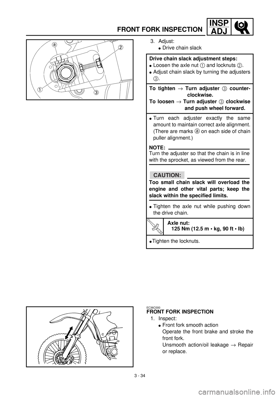
lLoosen the axle nut 1 and locknuts 2.
lAdjust chain slack by turning the adjusters
3.
To tighten ® Turn adjuster 3 counter-
clockwise.
To loosen ® Turn adjuster 3 clockwise
and push wheel forward.
lTurn each adjuster exactly the same
amount to maintain correct axle alignment.
(There are marks a on each side of chain
puller alignment.)
lTighten the axle nut while pushing down
the drive chain.
T R..
Axle nut:
125 Nm (12.5 m • kg, 90 ft • lb)
lTighten the locknuts.
NOTE:
Turn the adjuster so that the chain is in line
with the sprocket, as viewed from the rear.
CAUTION:
Too small chain slack will overload the
engine and other vital parts; keep the
slack within the specified limits.
EC36C000
FRONT FORK INSPECTION
1. Inspect:
lFront fork smooth action
Operate the front brake and stroke the
front fork.
Unsmooth action/oil leakage ® Repair
or replace.
Page 254 of 654
3 - 45
INSP
ADJ
LUBRICATION
EC36a041
LUBRICATION
To ensure smooth operation of all compo-
nents, lubricate your machine during setup,
after break-in, and after every race.
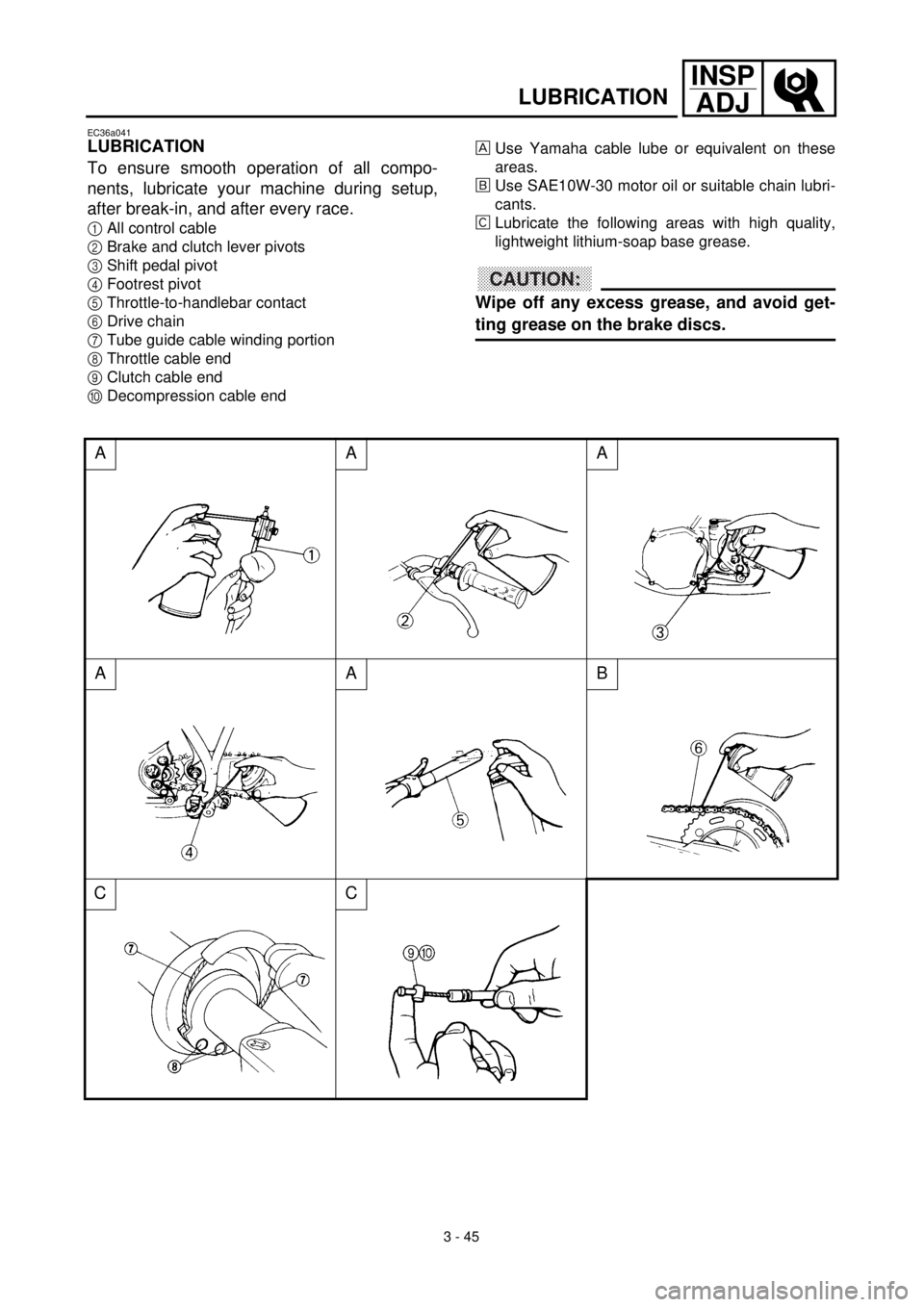
1All control cable
2Brake and clutch lever pivots
3Shift pedal pivot
4Footrest pivot
5Throttle-to-handlebar contact
6Drive chain
7Tube guide cable winding portion
8Throttle cable end
9Clutch cable end
0Decompression cable end
AAA
AAB
CC
Use Yamaha cable lube or equivalent on these
areas.
õUse SAE10W-30 motor oil or suitable chain lubri-
cants.
‚Lubricate the following areas with high quality,
lightweight lithium-soap base grease.
CAUTION:
Wipe off any excess grease, and avoid get-
ting grease on the brake discs.
Page 350 of 654
ENG
4 - 44
CLUTCH
CLUTCH
CLUTCH
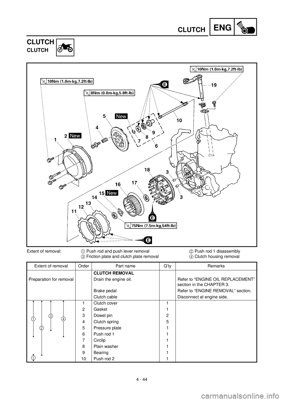
Extent of removal:1 Push rod and push lever removal2 Push rod 1 disassembly
3 Friction plate and clutch plate removal4 Clutch housing removal
Extent of removal Order Part name Q’ty Remarks
CLUTCH REMOVAL
Preparation for removal Drain the engine oil. Refer to “ENGINE OIL REPLACEMENT”
section in the CHAPTER 3.
Brake pedal Refer to “ENGINE REMOVAL” section.
Clutch cable Disconnect at engine side.
1 Clutch cover 1
2 Gasket 1
3 Dowel pin 2
4 Clutch spring 5
5 Pressure plate 1
6 Push rod 1 1
7 Circlip 1
8 Plain washer 1
9 Bearing 1
10 Push rod 2 1
4
1
1
2
3
Page 362 of 654
ENG
4 - 50
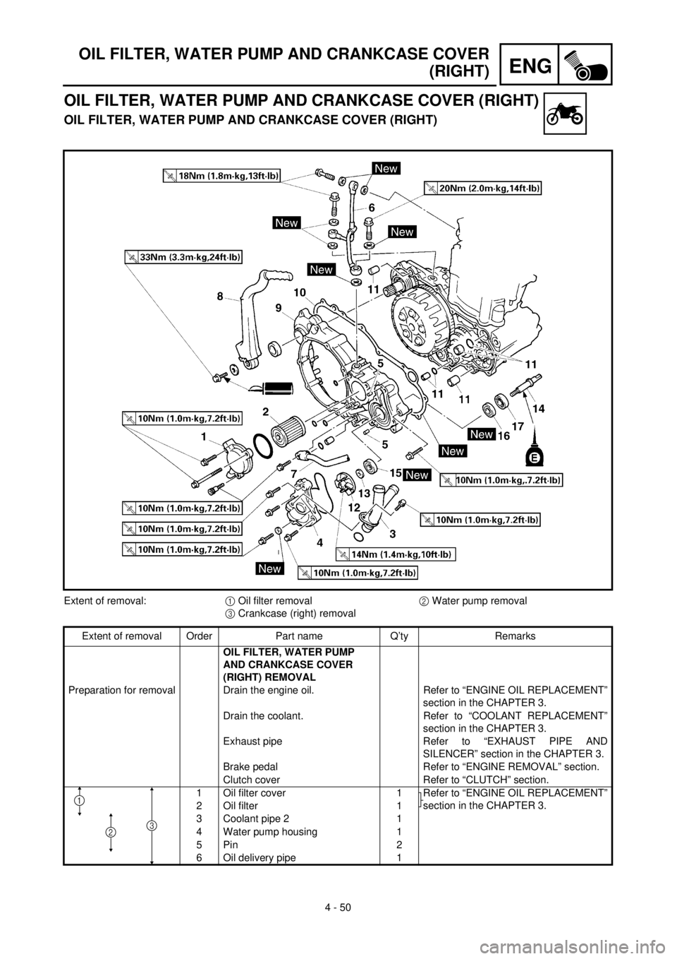
OIL FILTER, WATER PUMP AND CRANKCASE COVER
(RIGHT)
OIL FILTER, WATER PUMP AND CRANKCASE COVER (RIGHT)
OIL FILTER, WATER PUMP AND CRANKCASE COVER (RIGHT)
Extent of removal:1 Oil filter removal2 Water pump removal
3 Crankcase (right) removal
Extent of removal Order Part name Q’ty Remarks
OIL FILTER, WATER PUMP
AND CRANKCASE COVER
(RIGHT) REMOVAL
Preparation for removal Drain the engine oil. Refer to “ENGINE OIL REPLACEMENT”
section in the CHAPTER 3.
Drain the coolant. Refer to “COOLANT REPLACEMENT”
section in the CHAPTER 3.
Exhaust pipe Refer to “EXHAUST PIPE AND
SILENCER” section in the CHAPTER 3.
Brake pedal Refer to “ENGINE REMOVAL” section.
Clutch cover Refer to “CLUTCH” section.
1 Oil filter cover 1
Refer to “ENGINE OIL REPLACEMENT”
section in the CHAPTER 3.
2 Oil filter 1
3 Coolant pipe 2 1
4 Water pump housing 1
5 Pin 2
6 Oil delivery pipe 1
1
23
Page 412 of 654
ENG
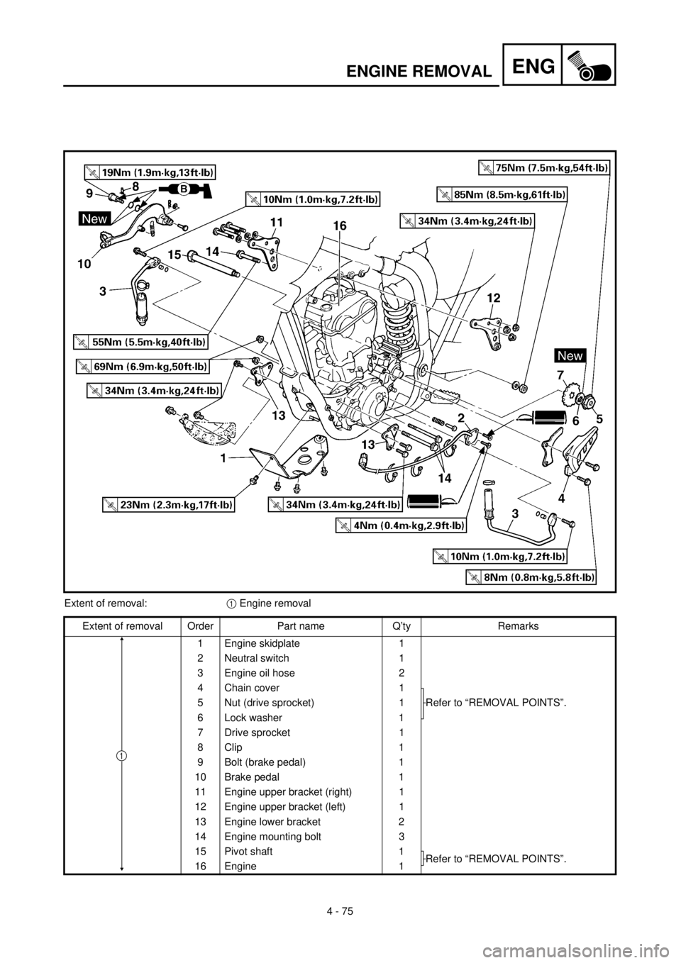
4 - 75
ENGINE REMOVAL
Extent of removal:1 Engine removal
Extent of removal Order Part name Q’ty Remarks
1 Engine skidplate 1
2 Neutral switch 1
3 Engine oil hose 2
4 Chain cover 1
Refer to “REMOVAL POINTS”. 5 Nut (drive sprocket) 1
6 Lock washer 1
7 Drive sprocket 1
8 Clip 1
9 Bolt (brake pedal) 1
10 Brake pedal 1
11 Engine upper bracket (right) 1
12 Engine upper bracket (left) 1
13 Engine lower bracket 2
14 Engine mounting bolt 3
15 Pivot shaft 1
Refer to “REMOVAL POINTS”.
16 Engine 1
1
Page 414 of 654
4 - 76
ENGENGINE REMOVAL
EC4M3000
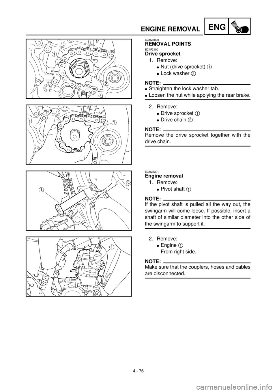
REMOVAL POINTS
EC4F3100
Drive sprocket
1. Remove:
lNut (drive sprocket) 1
lLock washer 2
NOTE:
lStraighten the lock washer tab.
lLoosen the nut while applying the rear brake.
2. Remove:
lDrive sprocket 1
lDrive chain 2
NOTE:
Remove the drive sprocket together with the
drive chain.
EC4M3301
Engine removal
1. Remove:
lPivot shaft 1
NOTE:
If the pivot shaft is pulled all the way out, the
swingarm will come loose. If possible, insert a
shaft of similar diameter into the other side of
the swingarm to support it.
2. Remove:
lEngine 1
From right side.
NOTE:
Make sure that the couplers, hoses and cables
are disconnected.
Page 416 of 654
4 - 77
ENGENGINE REMOVAL
EC4M5000
ASSEMBLY AND INSTALLATION
EC4M5160
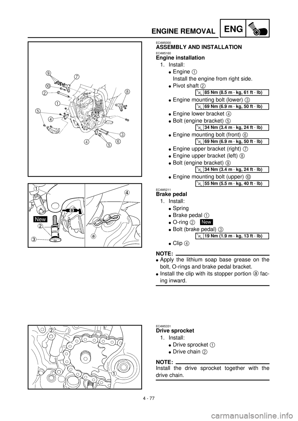
Engine installation
1. Install:
lEngine 1
Install the engine from right side.
lPivot shaft 2
lEngine mounting bolt (lower) 3
lEngine lower bracket 4
lBolt (engine bracket) 5
lEngine mounting bolt (front) 6
lEngine upper bracket (right) 7
lEngine upper bracket (left) 8
lBolt (engine bracket) 9
lEngine mounting bolt (upper) 0
EC4M5211
Brake pedal
1. Install:
lSpring
lBrake pedal 1
lO-ring 2
lBolt (brake pedal) 3
lClip 4
NOTE:
lApply the lithium soap base grease on the
bolt, O-rings and brake pedal bracket.
lInstall the clip with its stopper portion a fac-
ing inward.
T R..85 Nm (8.5 m · kg, 61 ft · lb)
T R..69 Nm (6.9 m · kg, 50 ft · lb)
T R..34 Nm (3.4 m · kg, 24 ft · lb)
T R..69 Nm (6.9 m · kg, 50 ft · lb)
T R..34 Nm (3.4 m · kg, 24 ft · lb)
T R..55 Nm (5.5 m · kg, 40 ft · lb)
New
T R..19 Nm (1.9 m · kg, 13 ft · lb)
EC4M5331
Drive sprocket
1. Install:
lDrive sprocket 1
lDrive chain 2
NOTE:
Install the drive sprocket together with the
drive chain.
Page 418 of 654
4 - 78
ENGENGINE REMOVAL
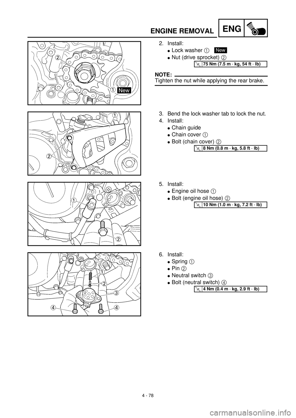
2. Install:
lLock washer 1
lNut (drive sprocket) 2
NOTE:
Tighten the nut while applying the rear brake.
New
T R..75 Nm (7.5 m · kg, 54 ft · lb)
3. Bend the lock washer tab to lock the nut.
4. Install:
lChain guide
lChain cover 1
lBolt (chain cover) 2
T R..8 Nm (0.8 m · kg, 5.8 ft · lb)
5. Install:
lEngine oil hose 1
lBolt (engine oil hose) 2
T R..10 Nm (1.0 m · kg, 7.2 ft · lb)
6. Install:
lSpring 1
lPin 2
lNeutral switch 3
lBolt (neutral switch) 4
T R..4 Nm (0.4 m · kg, 2.9 ft · lb)
Page 448 of 654
5 - 1
CHAS
EC500000
CHASSIS
EC590000
FRONT WHEEL AND REAR WHEEL
EC598000
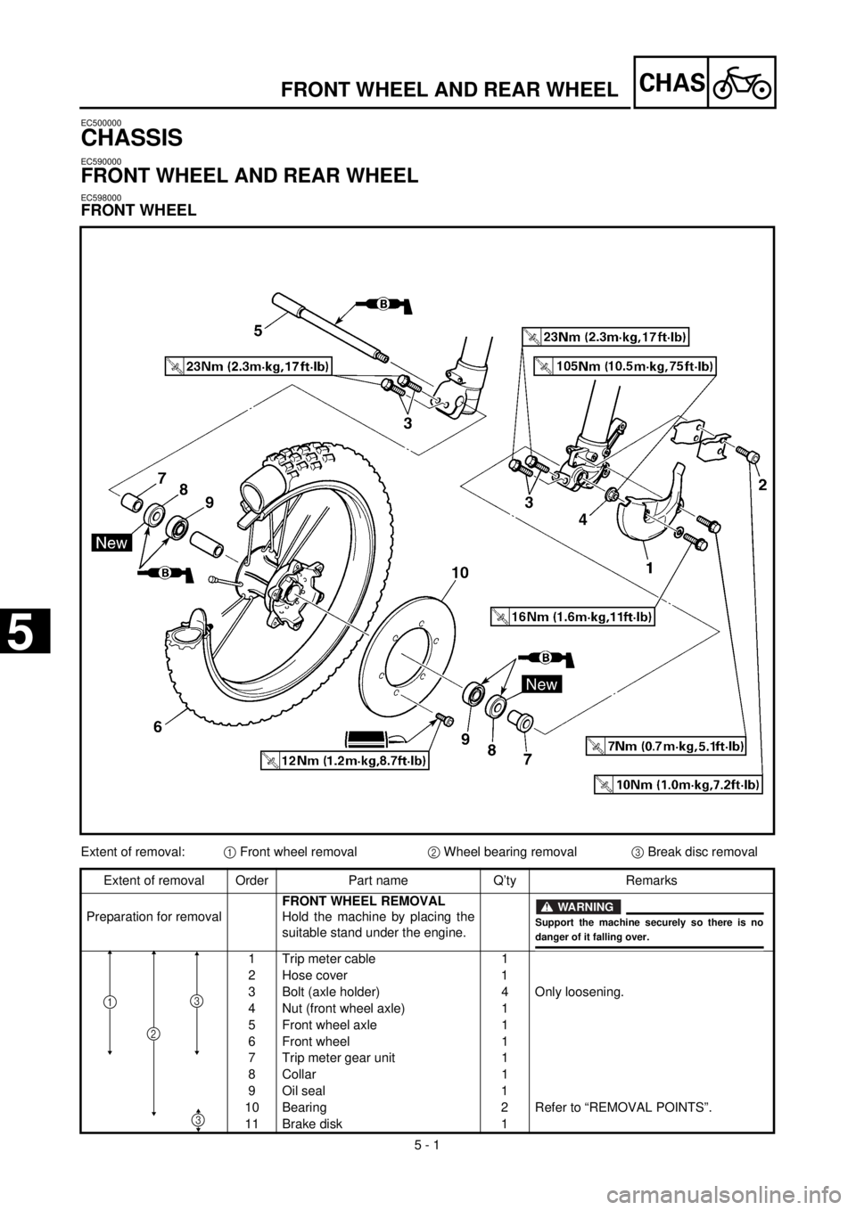
FRONT WHEEL
FRONT WHEEL AND REAR WHEEL
Extent of removal:
1
Front wheel removal
2
Wheel bearing removal
3
Break disc removal
Extent of removal Order Part name Q’ty Remarks
Preparation for removal
FRONT WHEEL REMOVAL
Hold the machine by placing the
suitable stand under the engine.
1 Trip meter cable 1
2 Hose cover 1
3 Bolt (axle holder) 4 Only loosening.
4 Nut (front wheel axle) 1
5 Front wheel axle 1
6 Front wheel 1
7 Trip meter gear unit 1
8 Collar 1
9 Oil seal 1
10 Bearing 2 Refer to “REMOVAL POINTS”.
11 Brake disk 1
WARNING
Support the machine securely so there is nodanger of it falling over.
2
31
3
5