length YAMAHA WR 400F 2000 Manuale duso (in Italian)
[x] Cancel search | Manufacturer: YAMAHA, Model Year: 2000, Model line: WR 400F, Model: YAMAHA WR 400F 2000Pages: 654, PDF Dimensioni: 60.12 MB
Page 308 of 654
4 - 23
ENGCAMSHAFTS
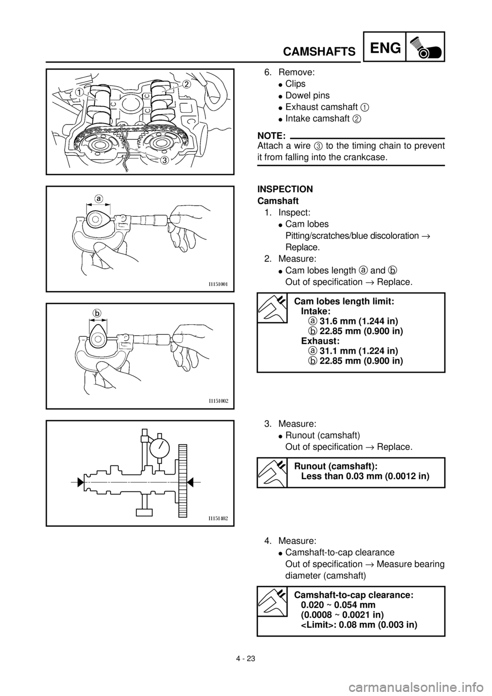
6. Remove:
lClips
lDowel pins
lExhaust camshaft 1
lIntake camshaft 2
NOTE:
Attach a wire 3 to the timing chain to prevent
it from falling into the crankcase.
INSPECTION
Camshaft
1. Inspect:
lCam lobes
Pitting/scratches/blue discoloration ®
Replace.
2. Measure:
lCam lobes length a and b
Out of specification ® Replace.
Cam lobes length limit:
Intake:
a 31.6 mm (1.244 in)
b 22.85 mm (0.900 in)
Exhaust:
a 31.1 mm (1.224 in)
b 22.85 mm (0.900 in)
3. Measure:
lRunout (camshaft)
Out of specification ® Replace.
Runout (camshaft):
Less than 0.03 mm (0.0012 in)
4. Measure:
lCamshaft-to-cap clearance
Out of specification ® Measure bearing
diameter (camshaft)
Camshaft-to-cap clearance:
0.020 ~ 0.054 mm
(0.0008 ~ 0.0021 in)
Page 332 of 654
4 - 35
ENG
VALVES AND VALVE SPRINGS
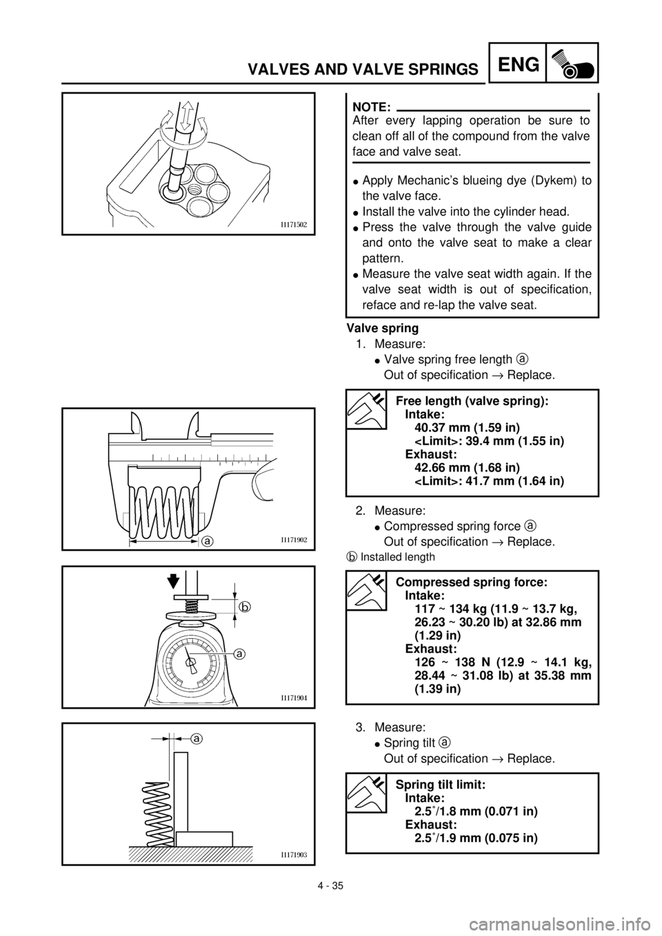
Valve spring
1. Measure:
lValve spring free length a
Out of specification ® Replace.
2. Measure:
lCompressed spring force a
Out of specification ® Replace.
bInstalled length
lApply Mechanic’s blueing dye (Dykem) to
the valve face.
lInstall the valve into the cylinder head.
lPress the valve through the valve guide
and onto the valve seat to make a clear
pattern.
lMeasure the valve seat width again. If the
valve seat width is out of specification,
reface and re-lap the valve seat.
Free length (valve spring):
Intake:
40.37 mm (1.59 in)
Exhaust:
42.66 mm (1.68 in)
Compressed spring force:
Intake:
117 ~ 134 kg (11.9 ~ 13.7 kg,
26.23 ~ 30.20 lb) at 32.86 mm
(1.29 in)
Exhaust:
126 ~ 138 N (12.9 ~ 14.1 kg,
28.44 ~ 31.08 lb) at 35.38 mm
(1.39 in)
NOTE:
After every lapping operation be sure to
clean off all of the compound from the valve
face and valve seat.
3. Measure:
lSpring tilt a
Out of specification ® Replace.
Spring tilt limit:
Intake:
2.5˚/1.8 mm (0.071 in)
Exhaust:
2.5˚/1.9 mm (0.075 in)
Page 354 of 654
4 - 46
ENGCLUTCH
EC493000
REMOVAL POINTS
EC483211
Clutch boss
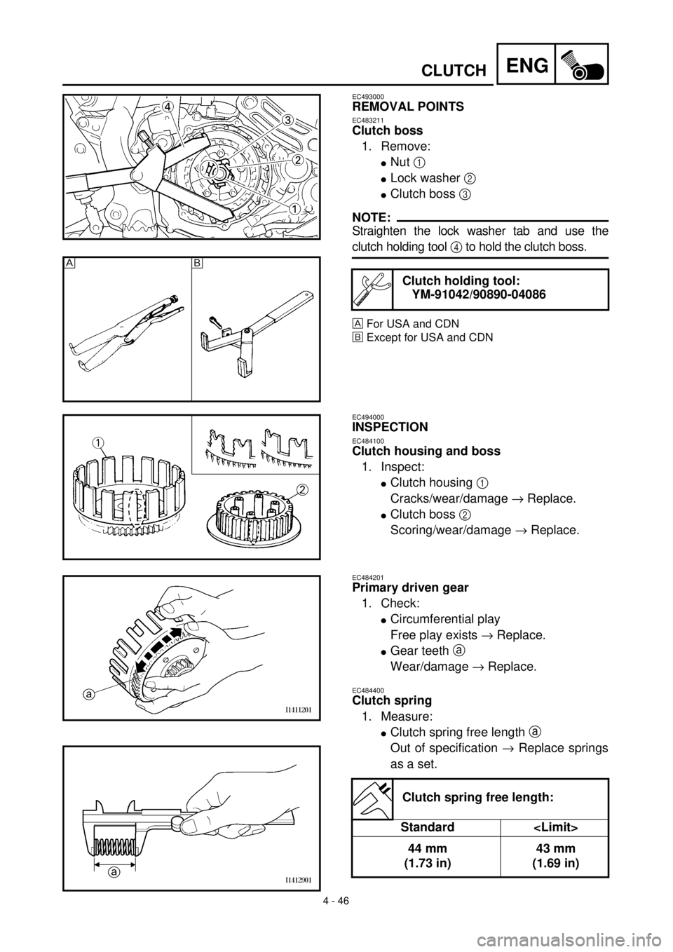
1. Remove:
lNut 1
lLock washer 2
lClutch boss 3
NOTE:
Straighten the lock washer tab and use the
clutch holding tool 4 to hold the clutch boss.
For USA and CDN
õExcept for USA and CDN
Clutch holding tool:
YM-91042/90890-04086
õ
EC494000
INSPECTION
EC484100
Clutch housing and boss
1. Inspect:
lClutch housing 1
Cracks/wear/damage ® Replace.
lClutch boss 2
Scoring/wear/damage ® Replace.
EC484201
Primary driven gear
1. Check:
lCircumferential play
Free play exists ® Replace.
lGear teeth a
Wear/damage ® Replace.
EC484400
Clutch spring
1. Measure:
lClutch spring free length a
Out of specification ® Replace springs
as a set.
Clutch spring free length:
Standard
44 mm
(1.73 in)43 mm
(1.69 in)
Page 508 of 654
5 - 31
CHAS
EC554200
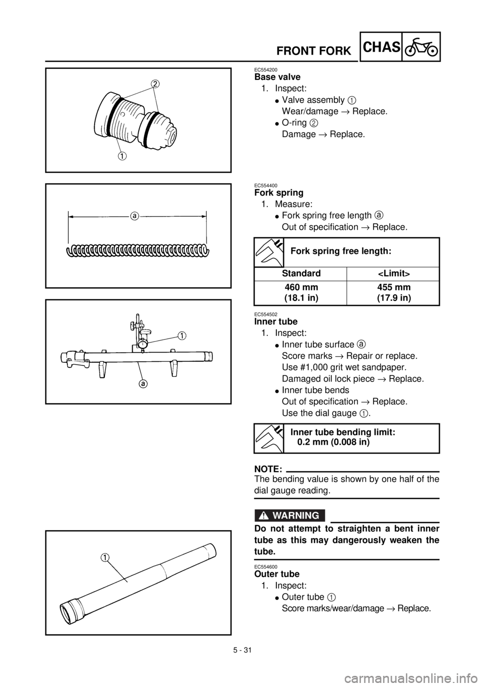
Base valve
1. Inspect:
lValve assembly 1
Wear/damage ® Replace.
lO-ring 2
Damage ® Replace.
EC554400
Fork spring
1. Measure:
lFork spring free length a
Out of specification ® Replace.
EC554502
Inner tube
1. Inspect:
lInner tube surface a
Score marks ® Repair or replace.
Use #1,000 grit wet sandpaper.
Damaged oil lock piece ® Replace.
lInner tube bends
Out of specification ® Replace.
Use the dial gauge 1.
NOTE:
The bending value is shown by one half of the
dial gauge reading.
WARNING
Do not attempt to straighten a bent inner
tube as this may dangerously weaken the
tube.
EC554600
Outer tube
1. Inspect:
lOuter tube 1
Score marks/wear/damage ® Replace.
Fork spring free length:
Standard
460 mm
(18.1 in)455 mm
(17.9 in)
Inner tube bending limit:
0.2 mm (0.008 in)
FRONT FORK
Page 570 of 654
5 - 62
CHASREAR SHOCK ABSORBER
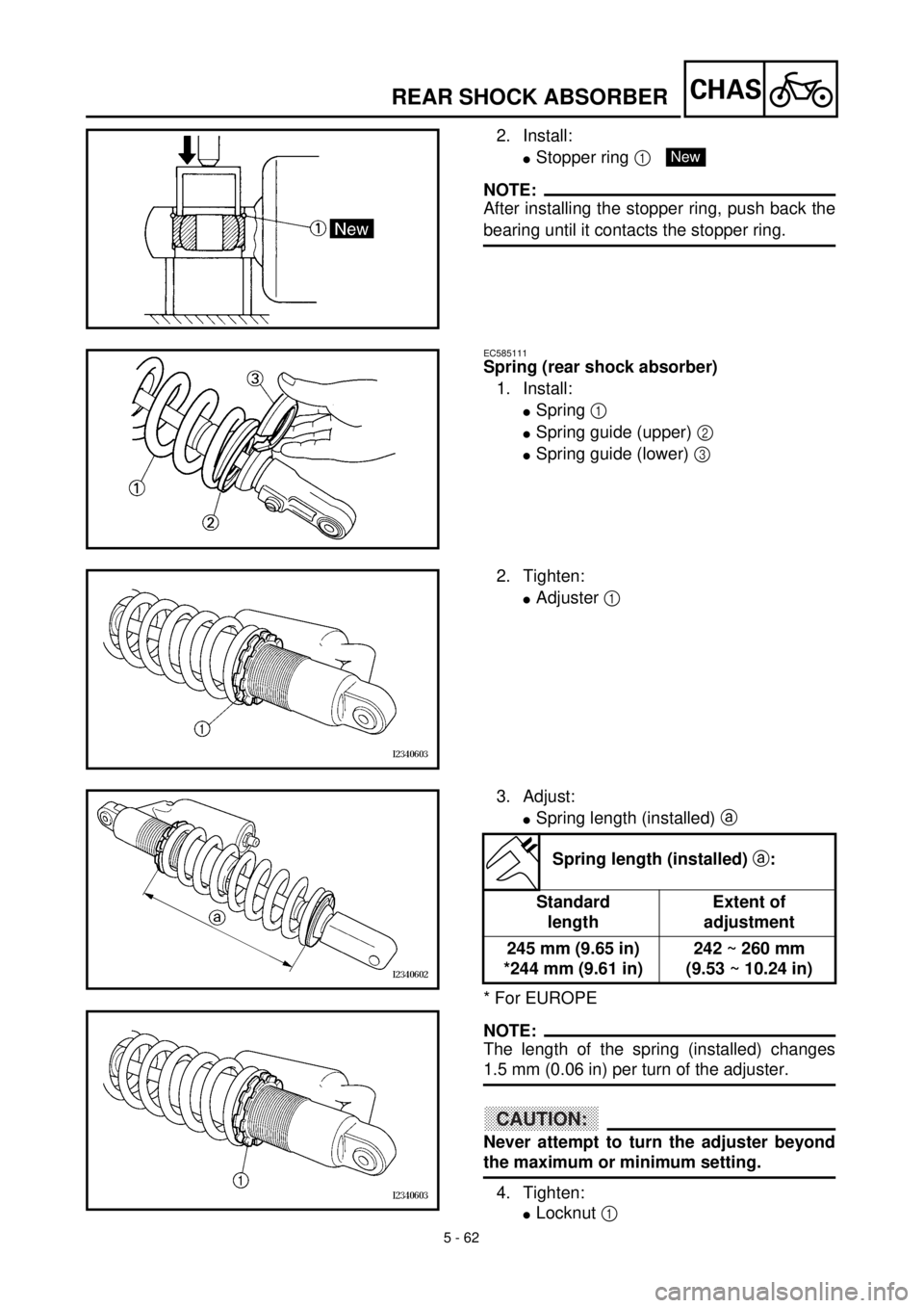
2. Install:
lStopper ring 1
NOTE:
After installing the stopper ring, push back the
bearing until it contacts the stopper ring.
New
EC585111
Spring (rear shock absorber)
1. Install:
lSpring 1
lSpring guide (upper) 2
lSpring guide (lower) 3
2. Tighten:
lAdjuster 1
3. Adjust:
lSpring length (installed) a
* For EUROPE
NOTE:
The length of the spring (installed) changes
1.5 mm (0.06 in) per turn of the adjuster.
CAUTION:
Never attempt to turn the adjuster beyond
the maximum or minimum setting.
4. Tighten:
lLocknut 1
Spring length (installed) a:
Standard
lengthExtent of
adjustment
245 mm (9.65 in)
*244 mm (9.61 in)242 ~ 260 mm
(9.53 ~ 10.24 in)
Page 638 of 654
7 - 16
TUN
EC72B000
Rear suspension setting
The rear suspension setting should be made
depending on the rider’s feeling of an actual
run and the circuit conditions.
The rear suspension setting includes the fol-
lowing two factors:
1. Setting of spring preload
lChange the set length of the spring.
lChange the spring.
2. Setting of damping force
lChange the rebound damping.
lChange the compression damping.
EC72C001
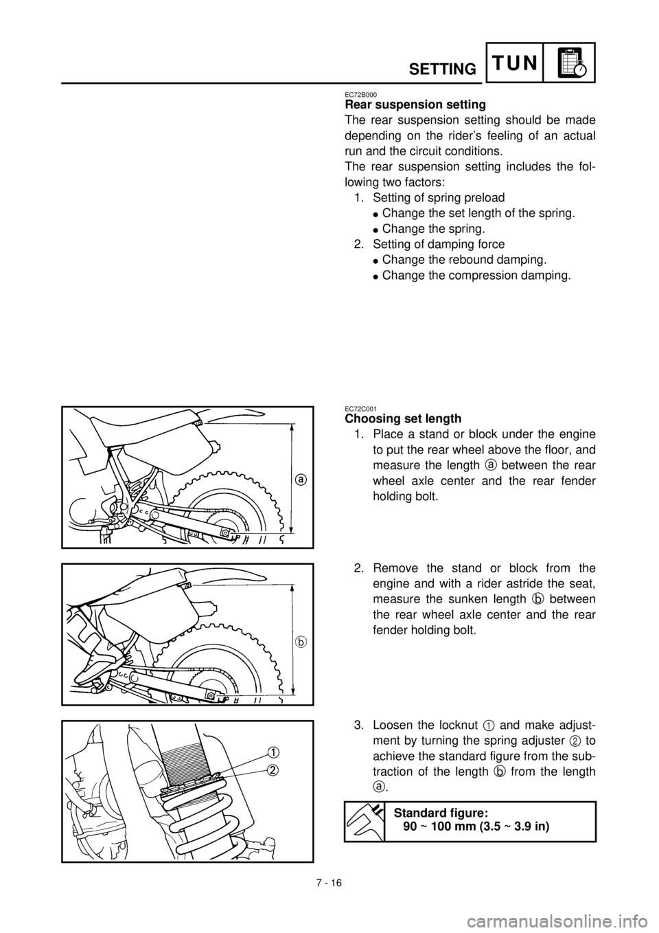
Choosing set length
1. Place a stand or block under the engine
to put the rear wheel above the floor, and
measure the length a between the rear
wheel axle center and the rear fender
holding bolt.
2. Remove the stand or block from the
engine and with a rider astride the seat,
measure the sunken length b between
the rear wheel axle center and the rear
fender holding bolt.
3. Loosen the locknut 1 and make adjust-
ment by turning the spring adjuster 2 to
achieve the standard figure from the sub-
traction of the length b from the length
a.
Standard figure:
90 ~ 100 mm (3.5 ~ 3.9 in)
SETTING
Page 640 of 654

7 - 17
TUN
NOTE:
lIf the machine is new and after it is broken in,
the same set length of the spring may
change because of the initial fatigue, etc. of
the spring. Therefore, be sure to make re-
evaluation.
lIf the standard figure cannot be achieved by
adjusting the spring adjuster and changing
the spring set length, replace the spring with
an optional one and make re-adjustment.
EC72G001
Setting of spring after replacement
After replacement, be sure to adjust the spring
to the set length and [sunken length 90 ~
100 mm (3.5 ~ 3.9 in)] set it.
1. Use of soft spring
lSet the soft spring for less rebound
damping to compensate for its less
spring load. Run with the rebound
damping adjuster one or two clicks on
the softer side and readjust it to suit
your preference.
2. Use of stiff spring
lSet the soft spring for more rebound
damping to compensate for its greater
spring load. Run with the rebound
damping adjuster one or two clicks on
the stiffer side and readjust it to suit
your preference.
*Adjusting the rebound damping will be
followed more or less by a change in the
compression damping. For correction,
turn the low compression damping
adjuster on the softer side.
SETTING
Page 642 of 654
7 - 18
TUNSETTING
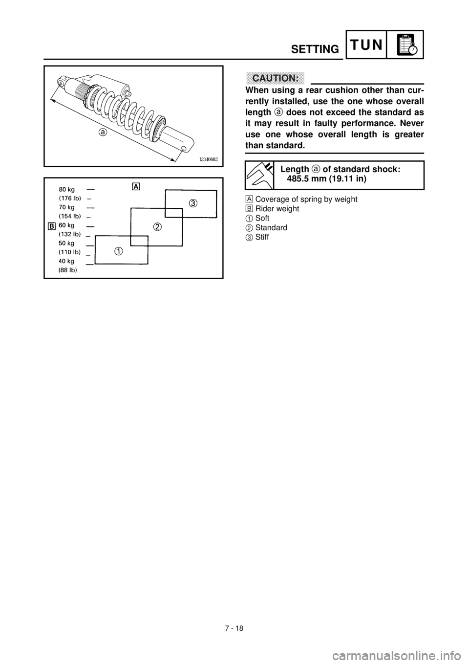
CAUTION:
When using a rear cushion other than cur-
rently installed, use the one whose overall
length a does not exceed the standard as
it may result in faulty performance. Never
use one whose overall length is greater
than standard.
Coverage of spring by weight
õRider weight
1Soft
2Standard
3Stiff
Length a of standard shock:
485.5 mm (19.11 in)
Page 644 of 654
![YAMAHA WR 400F 2000 Manuale duso (in Italian) 7 - 19
TUN
EC72Q000
Rear shock absorber setting parts
lRear shock spring 1
[Equal pitch spring]
* For EUROPE
[Unequal pitch spring]
NOTE:
lThe unequal pitch spring is softer in initial
characteristic YAMAHA WR 400F 2000 Manuale duso (in Italian) 7 - 19
TUN
EC72Q000
Rear shock absorber setting parts
lRear shock spring 1
[Equal pitch spring]
* For EUROPE
[Unequal pitch spring]
NOTE:
lThe unequal pitch spring is softer in initial
characteristic](/img/51/52440/w960_52440-643.png)
7 - 19
TUN
EC72Q000
Rear shock absorber setting parts
lRear shock spring 1
[Equal pitch spring]
* For EUROPE
[Unequal pitch spring]
NOTE:
lThe unequal pitch spring is softer in initial
characteristic than the equal pitch spring and
is difficult to bottom out under full compres-
sion.
lThe I.D. color a is marked at the end of the
spring.
TYPESPRING
RATESPRING
PART NUMBERI.D.
COLOR/
POINTSPRING
FREE
LENGTH
SOFT4.4
4.65DH-22212-70
5DH-22212-10Brown/1
Green/1260
260
*STD 4.8 5DH-22212-20 Red/1 260
STD 5.0 5DH-22212-30 Black/1 260
STIFF5.2
5.4
5.65DH-22212-40
5DH-22212-50
5DH-22212-60Blue/1
Yellow/1
Pink/1260
265
265
TYPESPRING
RATE
(approx.)SPRING
PART NUMBERI.D.
COLOR/
POINTSPRING
FREE
LENGTH
SOFT
STIFF4.6
4.8
5.0
5.2
5.4
5.65ET-22212-20
5ET-22212-00
5ET-22212-10
5ET-22212-30
5ET-22212-40
5ET-22212-50Green/2
Red/2
Black/2
Blue/2
Yellow/2
Pink/2275
275
275
275
275
280
lExtent of adjustment (spring length) b
SPRING FREE
LENGTHEXTENT OF
ADJUSTMENT
260 mm (10.24 in)242 ~ 260 mm
(9.53 ~ 10.24 in)
265 mm (10.43 in)247 ~ 265 mm
(9.72 ~ 10.43 in)
275 mm (10.83 in)257 ~ 275 mm
(10.12 ~ 10.83 in)
280 mm (11.02 in)262 ~ 280 mm
(10.31 ~ 11.02 in)
SETTING
Page 646 of 654

7 - 20
TUNSETTING
EC72H002
Suspension setting
lFront fork
NOTE:
lIf any of the following symptoms is experienced with the standard position as the base, make
resetting by reference to the adjustment procedure given in the same chart.
lBefore any change, set the rear shock absorber sunken length to the standard figure 90 ~
100 mm (3.5 ~ 3.9 in).
SymptomSection
Check Adjust
JumpLarge
gapMedium
gapSmall
gap
Stiff over entire range
CCC
Compression damping
Oil level (oil amount)
SpringTurn adjuster counterclockwise (about 2 clicks) to
decrease damping.
Decrease oil level by about 5 ~ 10 mm (0.2 ~ 0.4 in).
Replace with soft spring.
Unsmooth movement
over entire range
CCCC
Outer tube
Inner tube
Under bracket tightening
torqueCheck for any bends, dents, and other noticeable
scars, etc. If any, replace affected parts.
Retighten to specified torque.
Poor initial movement
C
Rebound damping
Oil sealTurn adjuster counterclockwise (about 2 clicks) to
decrease damping.
Apply grease in oil seal wall.
Soft over entire range,
bottoming out
CC
Compression damping
Oil level (oil amount)
SpringTurn adjuster clockwise (about 2 clicks) to increase
damping.
Increase oil level by about 5 ~ 10 mm (0.2 ~ 0.4 in).
Replace with stiff spring.
Stiff toward stroke end
COil level (oil amount) Decrease oil level by about 5 mm (0.2 in).
Soft toward stroke end,
bottoming out
COil level (oil amount) Increase oil level by about 5 mm (0.2 in).
Stiff initial movement
CCCCCompression dampingTurn adjuster counterclockwise (about 2 clicks) to
decrease damping.
Low front, tending to
lower front posture
CC
Compression damping
Rebound damping
Balance with rear end
Oil level (oil amount)Turn adjuster clockwise (about 2 clicks) to increase
damping.
Turn adjuster counterclockwise (about 2 clicks) to
decrease damping.
Set sunken length for 95 ~ 100 mm (3.7 ~ 3.9 in) when
one passenger is astride seat (lower rear posture).
Increase oil level by about 5 mm (0.2 in).
“Obtrusive” front, tend-
ing to upper front pos-
ture
CC
Compression damping
Balance with rear end
Spring
Oil lever (oil amount)Turn adjuster counterclockwise (about 2 clicks) to
decrease damping.
Set sunken length for 90 ~ 95 mm (3.5 ~ 3.7 in) when
one passenger is astride seat (upper rear posture).
Replace with soft spring.
Decrease oil level by about 5 ~ 10 mm (0.2 ~ 0.4 in).