lights YAMAHA WR 400F 2000 Notices Demploi (in French)
[x] Cancel search | Manufacturer: YAMAHA, Model Year: 2000, Model line: WR 400F, Model: YAMAHA WR 400F 2000Pages: 654, PDF Size: 60.12 MB
Page 26 of 654
1 - 1
GEN
INFO
DESCRIPTION
EC100000
GENERAL INFORMATION
EC110000
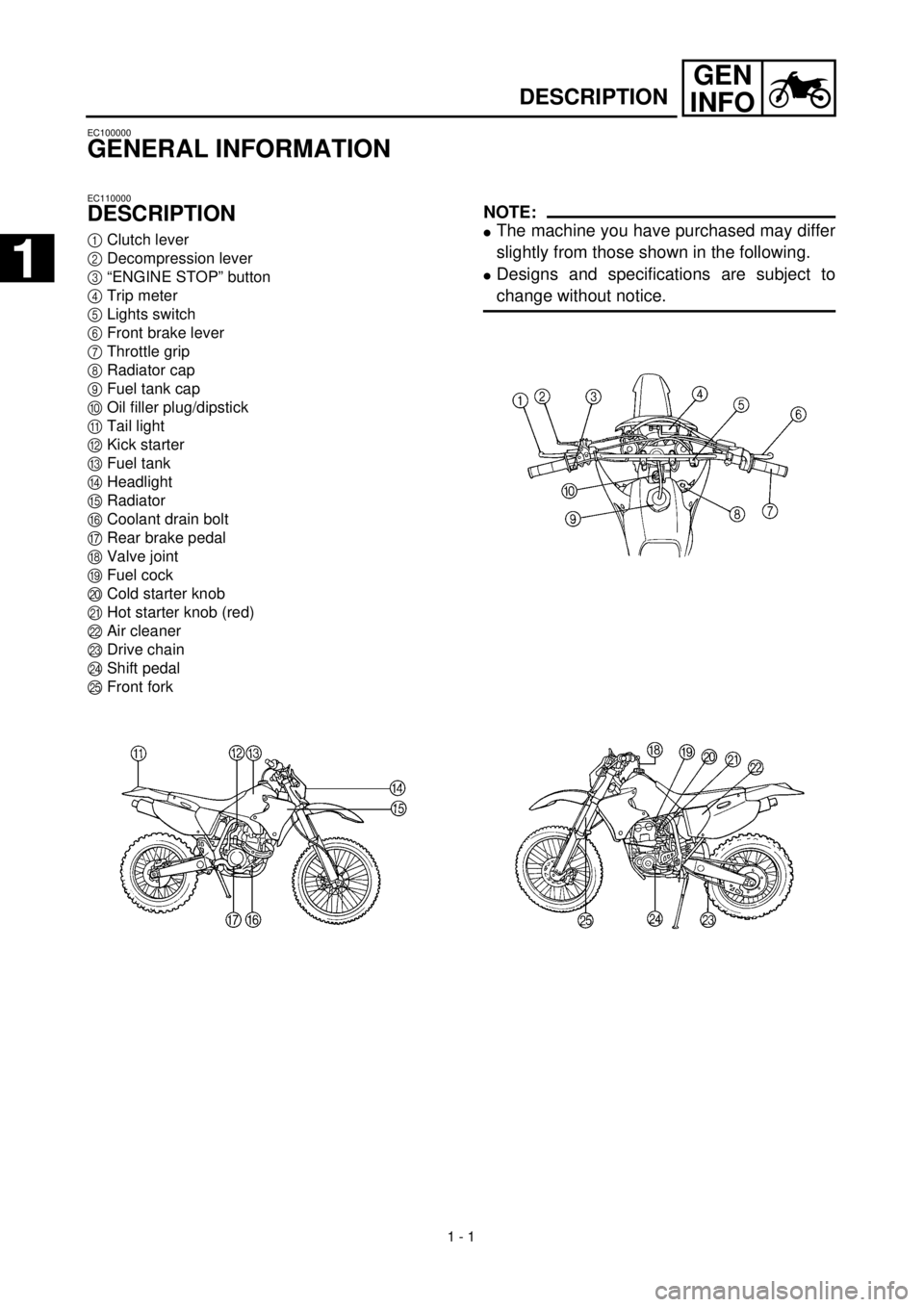
DESCRIPTION
1
Clutch lever
2
Decompression lever
3
“ENGINE STOP” button
4
Trip meter
5
Lights switch
6
Front brake lever
7
Throttle grip
8
Radiator cap
9
Fuel tank cap
0
Oil filler plug/dipstick
A
Tail light
B
Kick starter
C
Fuel tank
D
Headlight
E
Radiator
F
Coolant drain bolt
G
Rear brake pedal
H
Valve joint
I
Fuel cock
J
Cold starter knob
K
Hot starter knob (red)
L
Air cleaner
M
Drive chain
N
Shift pedal
O
Front fork
NOTE:
l
The machine you have purchased may differ
slightly from those shown in the following.
l
Designs and specifications are subject to
change without notice.
1
1
Page 54 of 654
1 - 12
GEN
INFO
CONTROL FUNCTIONS/FUEL
EC15F000
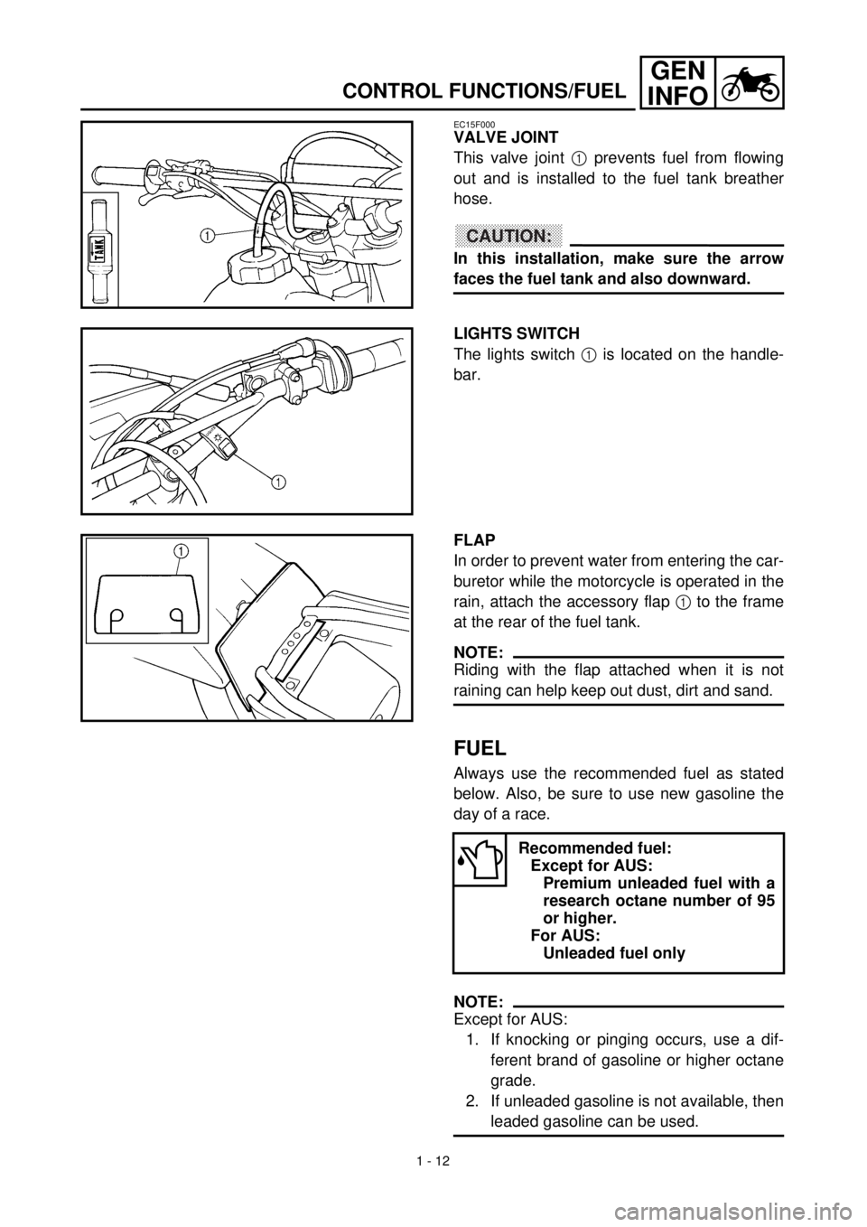
VALVE JOINT
This valve joint 1 prevents fuel from flowing
out and is installed to the fuel tank breather
hose.
CAUTION:
In this installation, make sure the arrow
faces the fuel tank and also downward.
LIGHTS SWITCH
The lights switch 1 is located on the handle-
bar.
FLAP
In order to prevent water from entering the car-
buretor while the motorcycle is operated in the
rain, attach the accessory flap 1 to the frame
at the rear of the fuel tank.
NOTE:
Riding with the flap attached when it is not
raining can help keep out dust, dirt and sand.
FUEL
Always use the recommended fuel as stated
below. Also, be sure to use new gasoline the
day of a race.
NOTE:
Except for AUS:
1. If knocking or pinging occurs, use a dif-
ferent brand of gasoline or higher octane
grade.
2. If unleaded gasoline is not available, then
leaded gasoline can be used.
Recommended fuel:
Except for AUS:
Premium unleaded fuel with a
research octane number of 95
or higher.
For AUS:
Unleaded fuel only
Page 148 of 654

2 - 21
SPEC
CABLE ROUTING DIAGRAM
EC240000
CABLE ROUTING DIAGRAM
1
Hose guide
2
Brake hose
3
Regulator
4
Fuel tank breather hose
5
Oil tank breather hose
6
Clamp
7
“ENGINE STOP” button lead
8
Sub wire harness
9
Tail light lead
0
TPS (throttle position sensor) lead
A
Neutral switch lead
B
Oil hose
C
Cylinder head breather hose
D
CDI magneto lead
E
Hose holder
F
Clutch cable
G
Decompression cable
H
Lights switch lead
I
Carburetor breather hose
J
Overflow hose
K
Coolant reservoir tank breather hose
Pass the fuel tank breather
hose behind handlebar, then
insert it into the steering shaft
hole.
õ
Pass the decompression
cable, “ENGINE STOP” but-
ton lead and lights switch lead
under where the oil hose is
attached.
‚
Pass the “ENGINE STOP” but-
ton lead, regulator lead and
lights switch lead along the
inner and side of the decom-
pression cable.
ë
Fasten the CDI magneto lead,
neutral switch lead “ENGINE
STOP” button lead and lights
switch lead to the frame with a
plastic locking tie.äPass the “ENGINE STOP”
button lead and lights switch
lead along the inner side of
the oil tank breather hose.
ìFasten the sub wire harness,
“ENGINE STOP” button lead
and lights switch lead to the
frame with a plastic locking
tie.
íPass the cylinder head
breather hose along the right
side of the oil tank breather
hose.
îFasten the sub wire harness
to the frame with a plastic
locking tie and cut off the tie
end.
éFasten the TPS lead (in the
sub wire harness) under the
frame.
Page 154 of 654
2 - 24
SPECCABLE ROUTING DIAGRAM
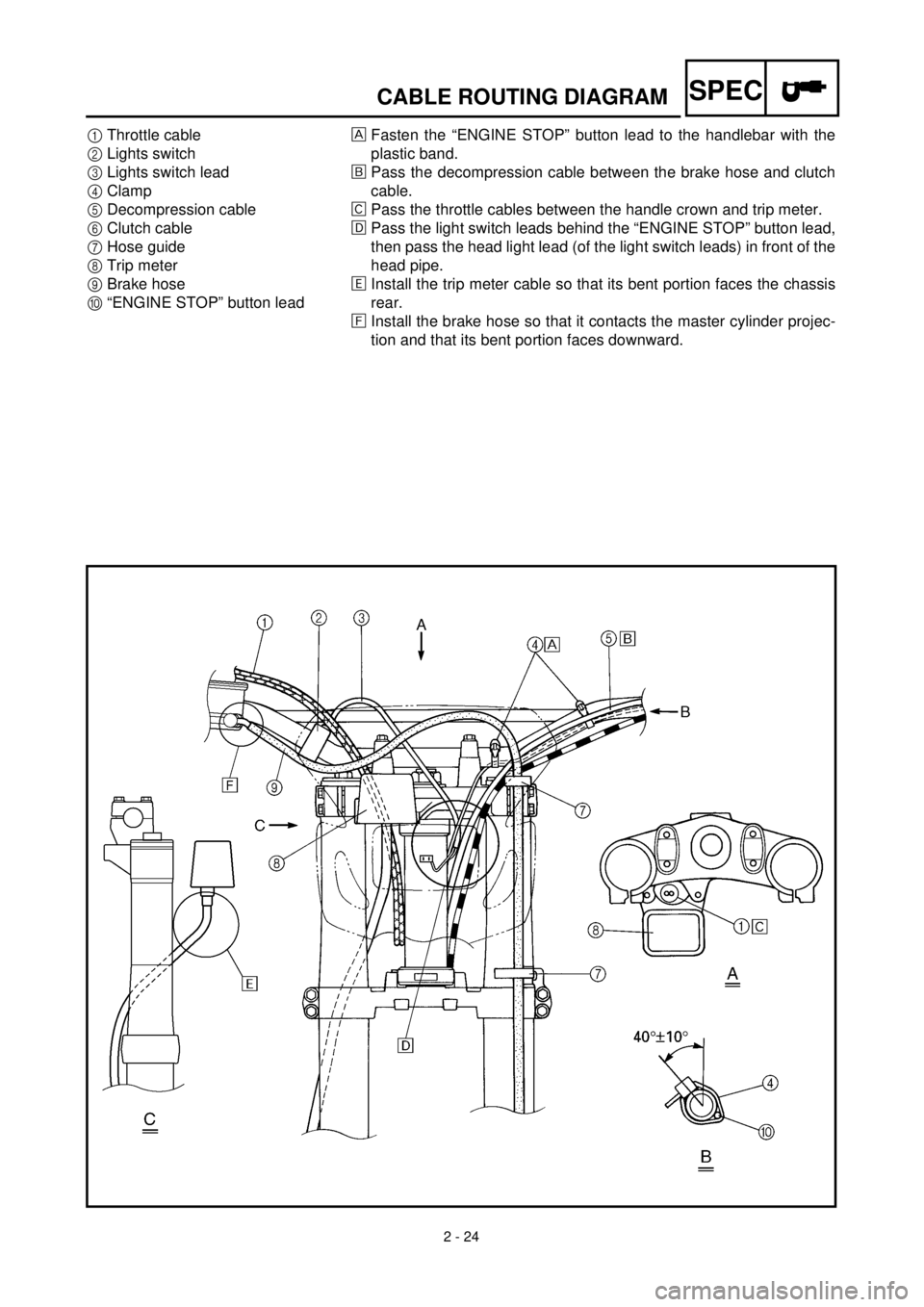
1Throttle cable
2Lights switch
3Lights switch lead
4Clamp
5Decompression cable
6Clutch cable
7Hose guide
8Trip meter
9Brake hose
0“ENGINE STOP” button leadFasten the “ENGINE STOP” button lead to the handlebar with the
plastic band.
õPass the decompression cable between the brake hose and clutch
cable.
‚Pass the throttle cables between the handle crown and trip meter.
ëPass the light switch leads behind the “ENGINE STOP” button lead,
then pass the head light lead (of the light switch leads) in front of the
head pipe.
äInstall the trip meter cable so that its bent portion faces the chassis
rear.
ìInstall the brake hose so that it contacts the master cylinder projec-
tion and that its bent portion faces downward.
Page 526 of 654
5 - 40
CHAS
EC5B0000
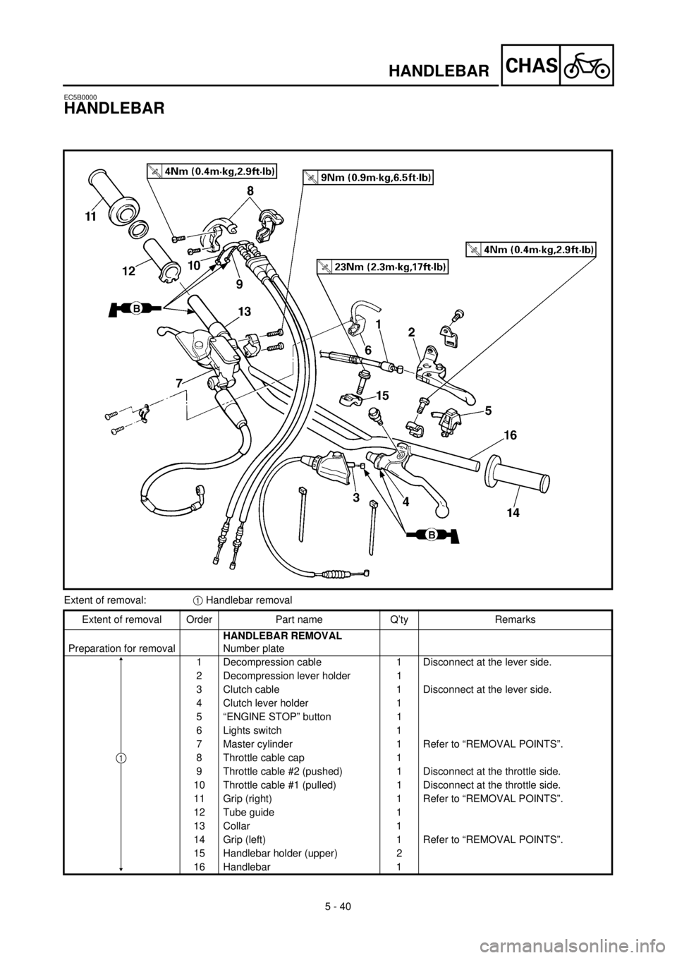
HANDLEBAR
Extent of removal:1 Handlebar removal
Extent of removal Order Part name Q’ty Remarks
Preparation for removalHANDLEBAR REMOVAL
Number plate
1 Decompression cable 1 Disconnect at the lever side.
2 Decompression lever holder 1
3 Clutch cable 1 Disconnect at the lever side.
4 Clutch lever holder 1
5 “ENGINE STOP” button 1
6 Lights switch 1
7 Master cylinder 1 Refer to “REMOVAL POINTS”.
8 Throttle cable cap 1
9 Throttle cable #2 (pushed) 1 Disconnect at the throttle side.
10 Throttle cable #1 (pulled) 1 Disconnect at the throttle side.
11 Grip (right) 1 Refer to “REMOVAL POINTS”.
12 Tube guide 1
13 Collar 1
14 Grip (left) 1 Refer to “REMOVAL POINTS”.
15 Handlebar holder (upper) 2
16 Handlebar 1
1
HANDLEBAR
Page 532 of 654
5 - 43
CHASHANDLEBAR
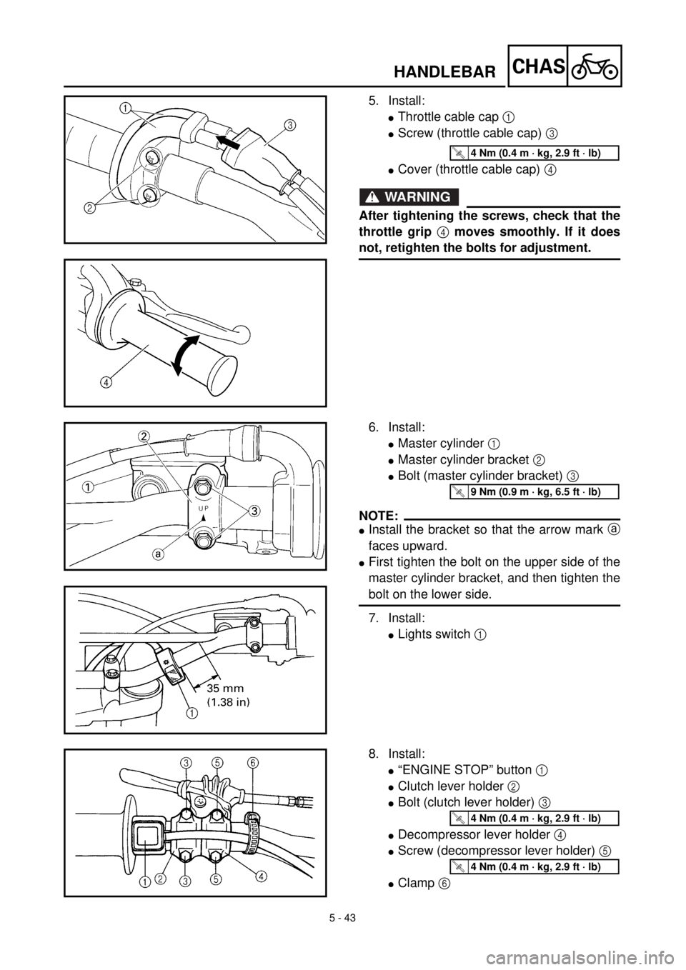
5. Install:
lThrottle cable cap 1
lScrew (throttle cable cap) 3
lCover (throttle cable cap) 4
WARNING
After tightening the screws, check that the
throttle grip 4 moves smoothly. If it does
not, retighten the bolts for adjustment.
T R..4 Nm (0.4 m · kg, 2.9 ft · lb)
6. Install:
lMaster cylinder 1
lMaster cylinder bracket 2
lBolt (master cylinder bracket) 3
NOTE:
lInstall the bracket so that the arrow mark a
faces upward.
lFirst tighten the bolt on the upper side of the
master cylinder bracket, and then tighten the
bolt on the lower side.
7. Install:
lLights switch 1
T R..9 Nm (0.9 m · kg, 6.5 ft · lb)
8. Install:
l“ENGINE STOP” button 1
lClutch lever holder 2
lBolt (clutch lever holder) 3
lDecompressor lever holder 4
lScrew (decompressor lever holder) 5
lClamp 6
T R..4 Nm (0.4 m · kg, 2.9 ft · lb)
T R..4 Nm (0.4 m · kg, 2.9 ft · lb)
Page 574 of 654

6 - 1
–+ELEC
ELECTRICAL COMPONENTS AND WIRING DIAGRAM
EC600000
ELECTRICAL
EC610000
ELECTRICAL COMPONENTS AND WIRING DIAGRAM
EC611000
ELECTRICAL COMPONENTS
1
Headlight
2
“ENGINE STOP” button
3
Regulator
4
TPS (throttle position sensor)
5
Tail light
6
CDI magneto
7
Neutral switch
8
Ignition coil
9
Spark plug
0
Lights switch
A
CDI unit
COLOR CODE
B...................... Black
Br .................... Brown
G ..................... Green
Gy ................... Gray
L ...................... Blue
O ..................... Orange
P...................... Pink
R ..................... Red
EC612000
WIRING DIAGRAM
Sb .................... Sky blue
W ..................... White
Y ...................... Yellow
B/L ................... Black/Blue
B/W .................. Black/White
L/W .................. Blue/White
R/W .................. Red/White
6
B/L
R/WL/W
LY
L
Y
B
1B L
L YBLB YL BY
BYYLB
5LB
BYBL
LB
3
7
4 8
9
W
R Br
G P
BP
B Br
G W
R
O
L B
Y Sb
B/LSb
B/L B
Y O
L
A
2
Y
Br
B/WBB/WB
PGR
WB
L YL Y
B B/L
SbSbW
Sb
WL/W
R/WL/W
R/WSb
W2
N
13
4
5
O
B
0
6
B/WGyB/WGy
Page 600 of 654
6 - 11
–+ELECLIGHTING SYSTEM
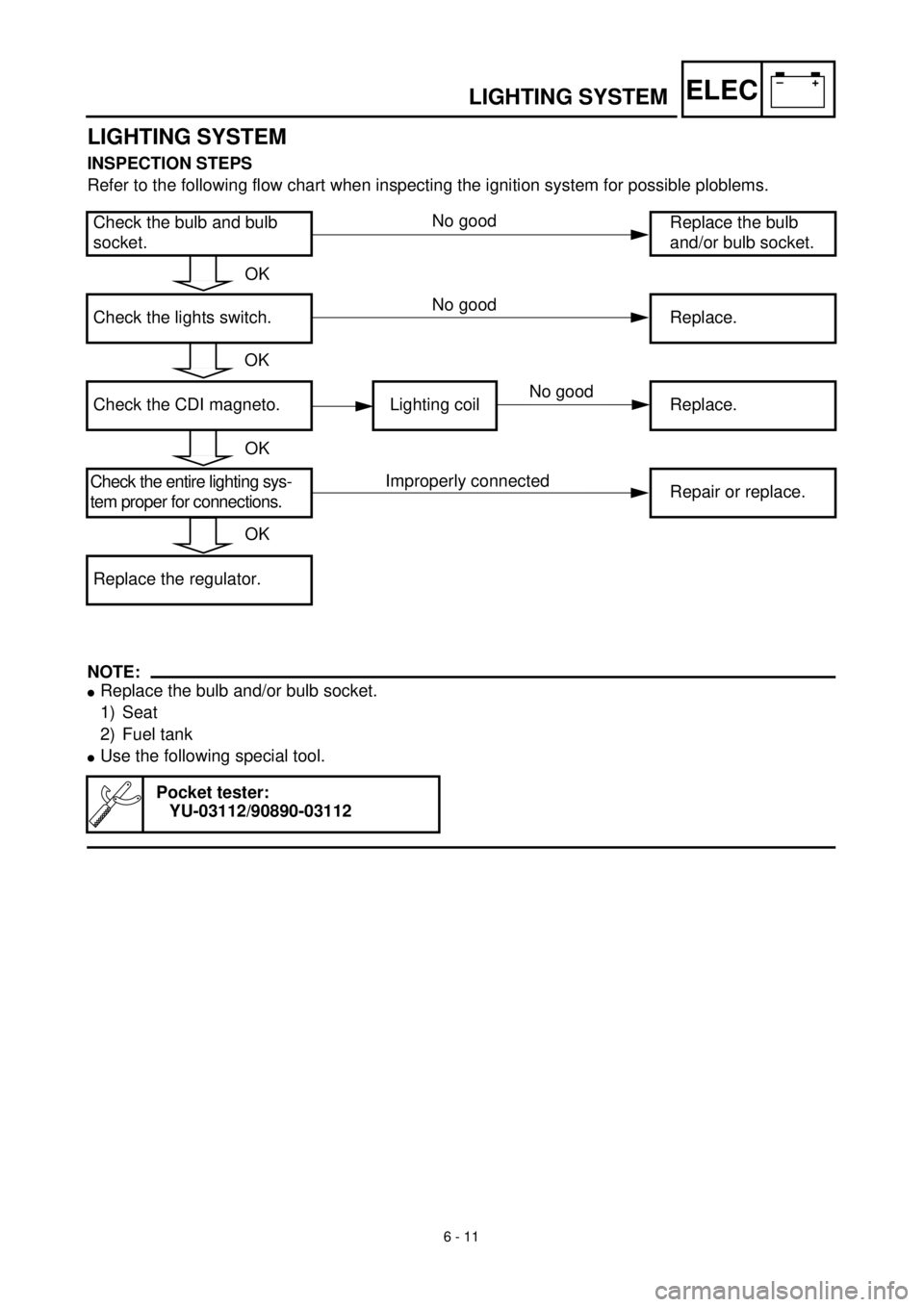
LIGHTING SYSTEM
INSPECTION STEPS
Refer to the following flow chart when inspecting the ignition system for possible ploblems.
NOTE:
lReplace the bulb and/or bulb socket.
1) Seat
2) Fuel tank
lUse the following special tool.
Check the bulb and bulb
socket.Replace the bulb
and/or bulb socket.
Check the lights switch. Replace.
Check the CDI magneto. Lighting coil Replace.
Check the entire lighting sys-
tem proper for connections.Repair or replace.
Replace the regulator.
Pocket tester:
YU-03112/90890-03112
OK
OK
OK
OK
No good
No good
Improperly connected
No good
Page 604 of 654
6 - 12
–+ELECLIGHTING SYSTEM
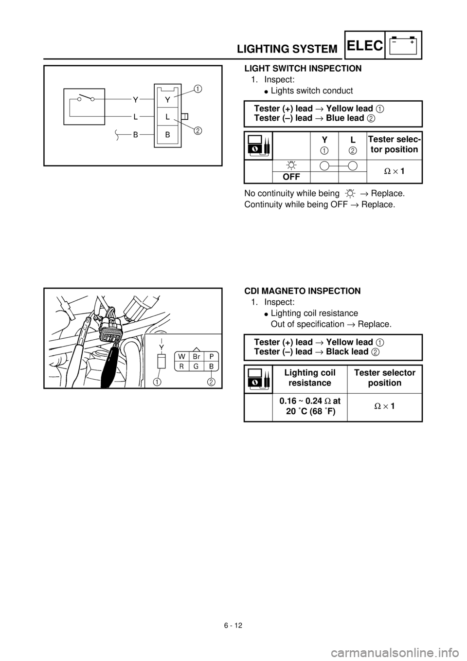
LIGHT SWITCH INSPECTION
1. Inspect:
lLights switch conduct
No continuity while being ® Replace.
Continuity while being OFF ® Replace. Tester (+) lead ® Yellow lead 1
Tester (–) lead ® Blue lead 2
Y
1L
2Tester selec-
tor position
W ´ 1
OFF
CDI MAGNETO INSPECTION
1. Inspect:
lLighting coil resistance
Out of specification ® Replace.
Tester (+) lead ® Yellow lead 1
Tester (–) lead ® Black lead 2
Lighting coil
resistanceTester selector
position
0.16 ~ 0.24 W at
20 ˚C (68 ˚F)W ´ 1