lock YAMAHA WR 400F 2000 Notices Demploi (in French)
[x] Cancel search | Manufacturer: YAMAHA, Model Year: 2000, Model line: WR 400F, Model: YAMAHA WR 400F 2000Pages: 654, PDF Size: 60.12 MB
Page 16 of 654
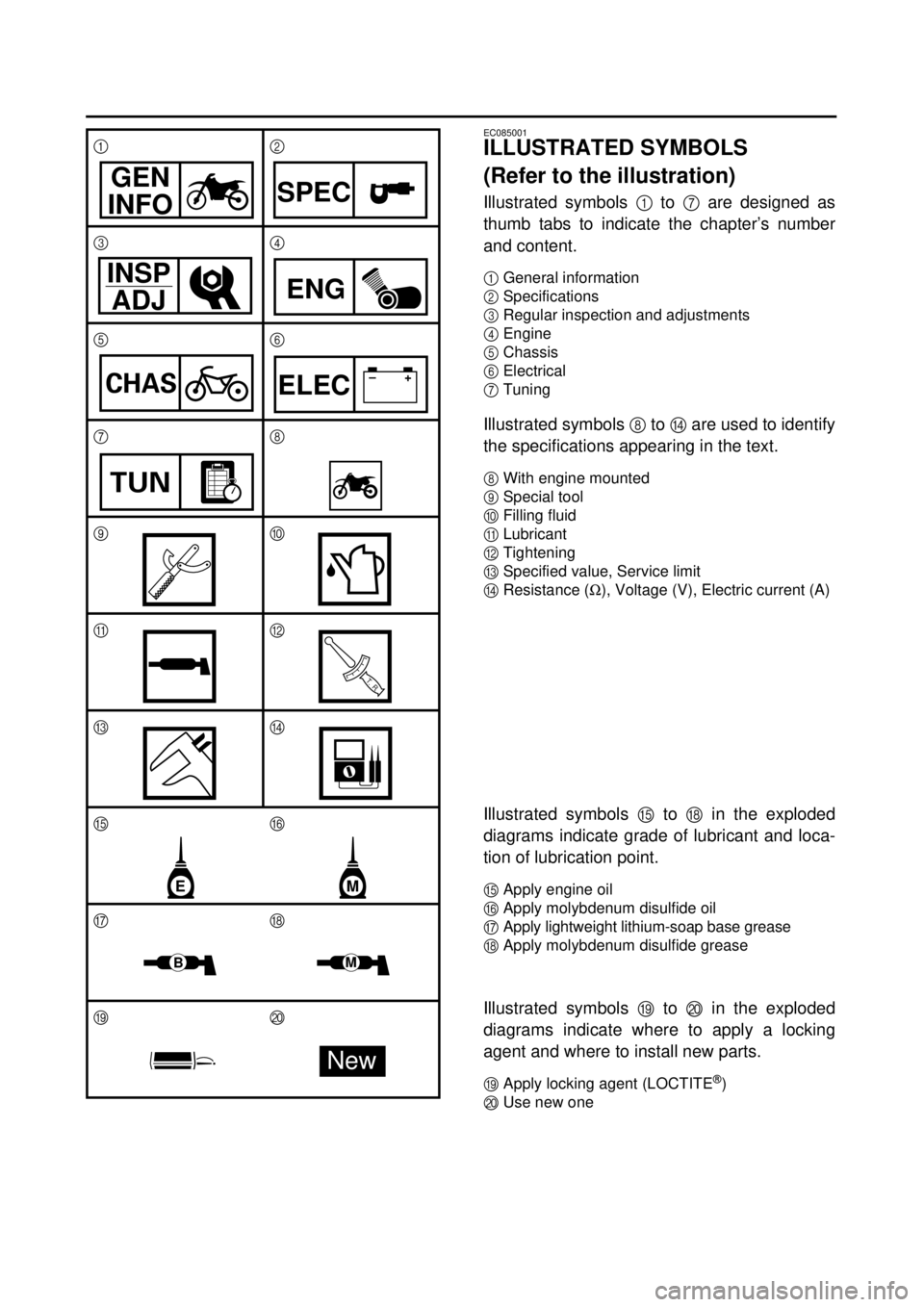
EC085001
ILLUSTRATED SYMBOLS
(Refer to the illustration)
Illustrated symbols
1
to
7
are designed as
thumb tabs to indicate the chapter’s number
and content.
1
General information
2
Specifications
3
Regular inspection and adjustments
4
Engine
5
Chassis
6
Electrical
7
Tuning
Illustrated symbols
8
to
D
are used to identify
the specifications appearing in the text.
8
With engine mounted
9
Special tool
0
Filling fluid
A
Lubricant
B
Tightening
C
Specified value, Service limit
D
Resistance (
W
), Voltage (V), Electric current (A)
Illustrated symbols
E
to
H
in the exploded
diagrams indicate grade of lubricant and loca-
tion of lubrication point.
E
Apply engine oil
F
Apply molybdenum disulfide oil
G
Apply lightweight lithium-soap base grease
H
Apply molybdenum disulfide grease
Illustrated symbols
I
to
J in the exploded
diagrams indicate where to apply a locking
agent and where to install new parts.
IApply locking agent (LOCTITE®)
JUse new one 12
34
56
78
90
AB
CD
EF
GH
IJ
GEN
INFOSPEC
INSP
ADJ
ENG
CHAS–+ELEC
TUN
T R..
ME
BM
New
Page 32 of 654
1 - 4
GEN
INFO
IMPORTANT INFORMATION
EC133000
GASKETS, OIL SEALS AND O-RINGS
1. All gaskets, oil seals, and O-rings should
be replaced when an engine is over-
hauled. All gasket surfaces, oil seal lips,
and O-rings must be cleaned.
2. Properly oil all mating parts and bearings
during reassembly. Apply grease to the
oil seal lips.
EC134000
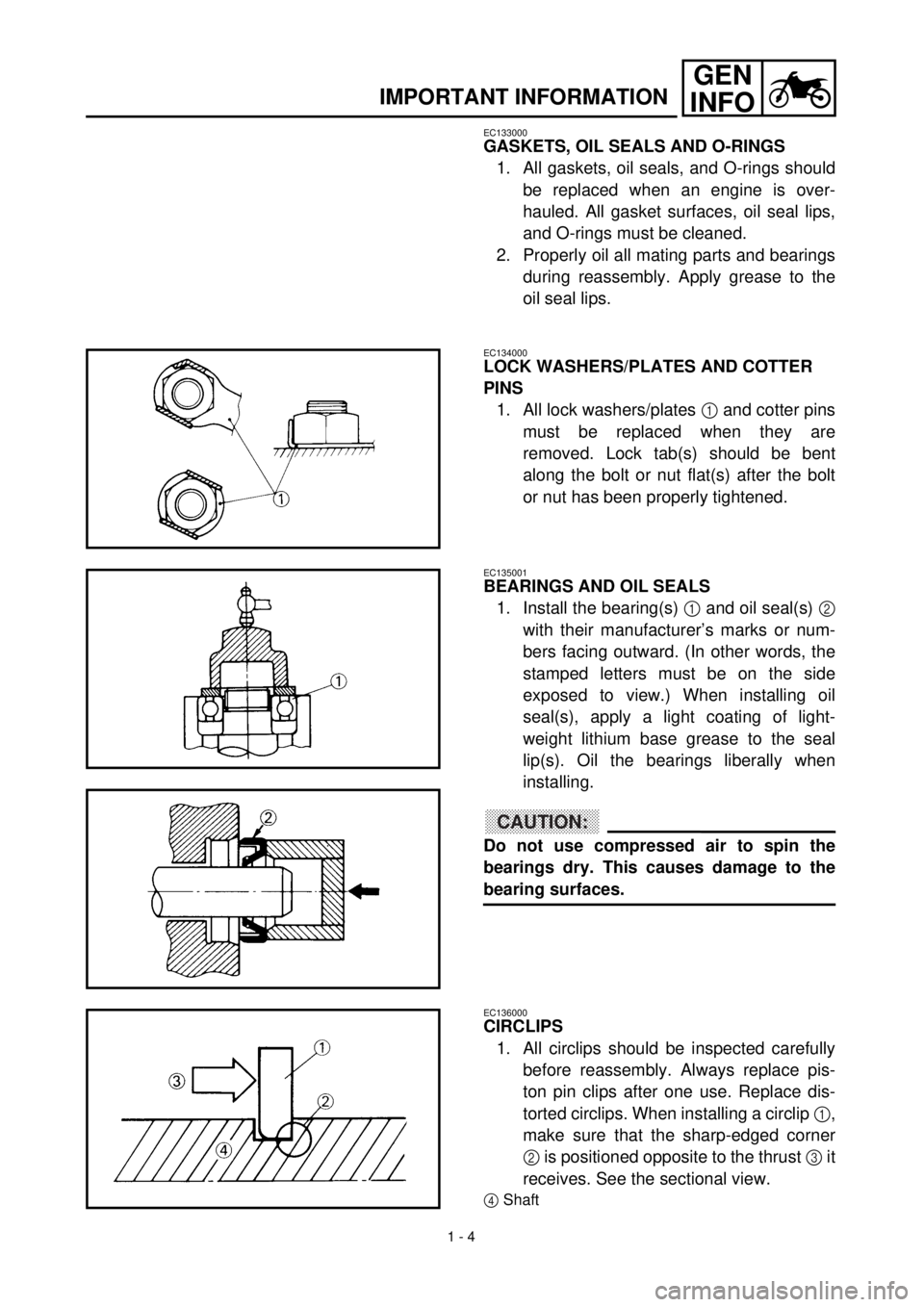
LOCK WASHERS/PLATES AND COTTER
PINS
1. All lock washers/plates
1
and cotter pins
must be replaced when they are
removed. Lock tab(s) should be bent
along the bolt or nut flat(s) after the bolt
or nut has been properly tightened.
EC135001
BEARINGS AND OIL SEALS
1. Install the bearing(s)
1
and oil seal(s)
2
with their manufacturer’s marks or num-
bers facing outward. (In other words, the
stamped letters must be on the side
exposed to view.) When installing oil
seal(s), apply a light coating of light-
weight lithium base grease to the seal
lip(s). Oil the bearings liberally when
installing.
CAUTION:
Do not use compressed air to spin the
bearings dry. This causes damage to the
bearing surfaces.
EC136000
CIRCLIPS
1. All circlips should be inspected carefully
before reassembly. Always replace pis-
ton pin clips after one use. Replace dis-
torted circlips. When installing a circlip
1,
make sure that the sharp-edged corner
2 is positioned opposite to the thrust 3 it
receives. See the sectional view.
4Shaft
Page 68 of 654

1 - 18
GEN
INFO
CLEANING AND STORAGE
EC1B0000
CLEANING AND STORAGE
EC1B1000
CLEANING
Frequent cleaning of your machine will
enhance its appearance, maintain good overall
performance, and extend the life of many com-
ponents.
1. Before washing the machine, block off
the end of the exhaust pipe to prevent
water from entering. A plastic bag
secured with a rubber band may be used
for this purpose.
2. If the engine is excessively greasy, apply
some degreaser to it with a paint brush.
Do not apply degreaser to the chain,
sprockets, or wheel axles.
3. Rinse the dirt and degreaser off with a
garden hose; use only enough pressure
to do the job.
CAUTION:
Excessive hose pressure may cause water
seepage and contamination of wheel bear-
ings, front forks, brakes and transmission
seals. Many expensive repair bills have
resulted from improper high pressure
detergent applications such as those avail-
able in coin-operated car washers.
4. After the majority of the dirt has been
hosed off, wash all surfaces with warm
water and a mild detergent. Use an old
toothbrush to clean hard-to-reach places.
5. Rinse the machine off immediately with
clean water, and dry all surfaces with a
soft towel or cloth.
6. Immediately after washing, remove
excess water from the chain with a paper
towel and lubricate the chain to prevent rust.
7. Clean the seat with a vinyl upholstery
cleaner to keep the cover pliable and
glossy.
8. Automotive wax may be applied to all
painted or chromed surfaces. Avoid com-
bination cleaner-waxes, as they may con-
tain abrasives.
9. After completing the above, start the
engine and allow it to idle for several min-
utes.
Page 70 of 654

1 - 19
GEN
INFO
CLEANING AND STORAGE
EC182001
STORAGE
If your machine is to be stored for 60 days or
more, some preventive measures must be
taken to avoid deterioration. After cleaning the
machine thoroughly, prepare it for storage as
follows:
1. Drain the fuel tank, fuel lines, and the car-
buretor float bowl.
2. Remove the spark plug, pour a table-
spoon of SAE 10W-30 motor oil in the
spark plug hole, and reinstall the plug.
With the engine stop switch pushed in,
kick the engine over several times to coat
the cylinder walls with oil.
3. Remove the drive chain, clean it thor-
oughly with solvent, and lubricate it. Rein-
stall the chain or store it in a plastic bag
tied to the frame.
4. Lubricate all control cables.
5. Block the frame up to raise the wheels off
the ground.
6. Tie a plastic bag over the exhaust pipe
outlet to prevent moisture from entering.
7. If the machine is to be stored in a humid
or salt-air environment, coat all exposed
metal surfaces with a film of light oil. Do
not apply oil to rubber parts or the seat
cover.
NOTE:
Make any necessary repairs before the
machine is stored.
Page 77 of 654
2 - 6
SPEC
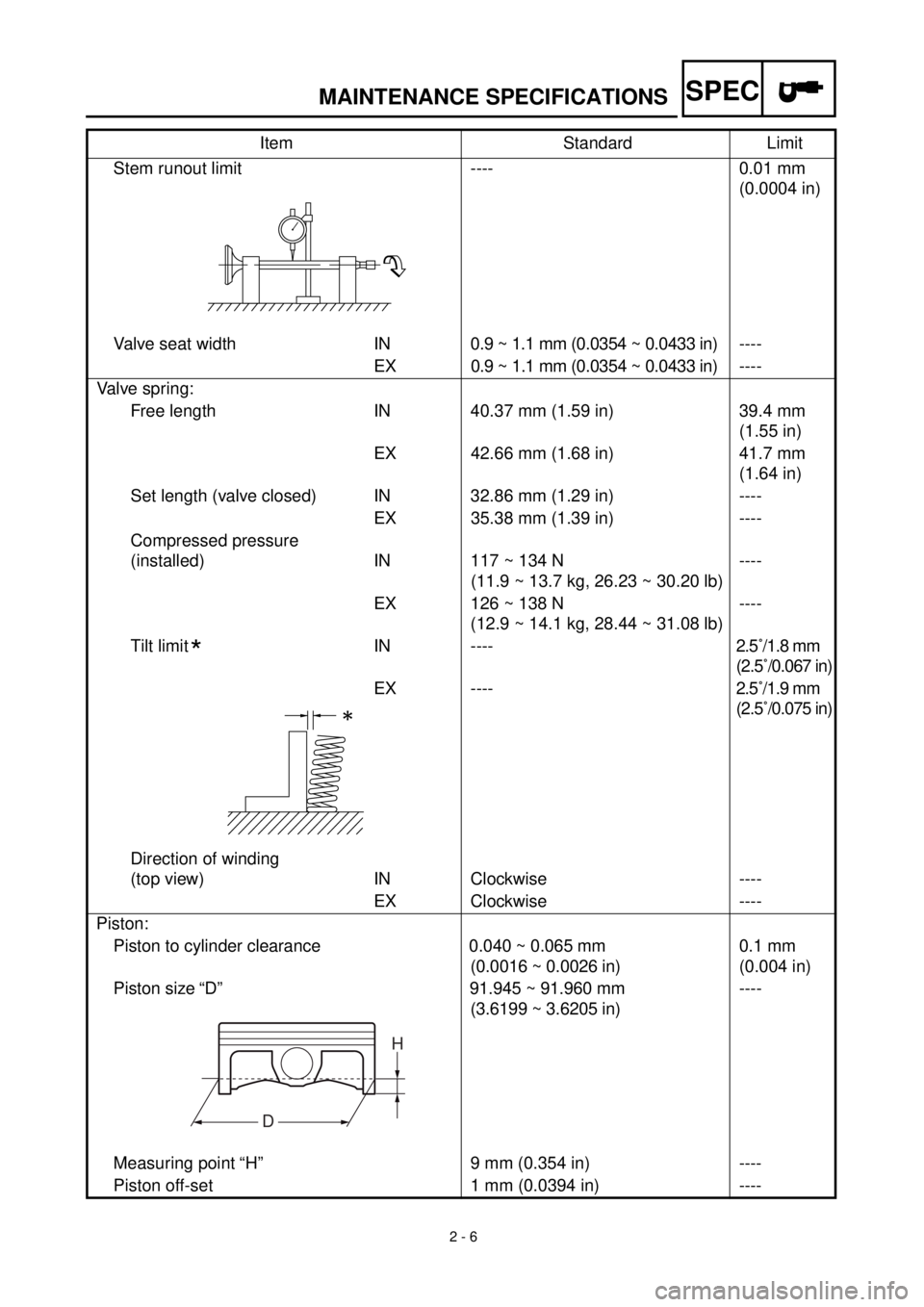
MAINTENANCE SPECIFICATIONS
Stem runout limit ---- 0.01 mm
(0.0004 in)
Valve seat width IN0.9 ~ 1.1 mm (0.0354 ~ 0.0433 in)----
EX 0.9 ~ 1.1 mm (0.0354 ~ 0.0433 in)----
Valve spring:
Free length IN 40.37 mm (1.59 in) 39.4 mm
(1.55 in)
EX 42.66 mm (1.68 in) 41.7 mm
(1.64 in)
Set length (valve closed) IN 32.86 mm (1.29 in) ----
EX 35.38 mm (1.39 in) ----
Compressed pressure
(installed) IN 117 ~ 134 N
(11.9 ~ 13.7 kg, 26.23 ~ 30.20 lb)----
EX 126 ~ 138 N
(12.9 ~ 14.1 kg, 28.44 ~ 31.08 lb)----
Tilt limit IN ----2.5˚/1.8 mm
(2.5˚/0.067 in)
EX ----2.5˚/1.9 mm
(2.5˚/0.075 in)
Direction of winding
(top view) IN Clockwise ----
EX Clockwise ----
Piston:
Piston to cylinder clearance 0.040 ~ 0.065 mm
(0.0016 ~ 0.0026 in)0.1 mm
(0.004 in)
Piston size “D” 91.945 ~ 91.960 mm
(3.6199 ~ 3.6205 in)----
Measuring point “H” 9 mm (0.354 in) ----
Piston off-set 1 mm (0.0394 in) ----Item Standard Limit
*
H
D
Page 86 of 654

2 - 15
SPECMAINTENANCE SPECIFICATIONS
HINWEIS:NOTE:
1. First, tighten the ring nut approximately 38 Nm (3.8 m • kg, 27 ft • lb) by using the ring nut
wrench, then loosen the ring nut one turn.
2. Retighten the ring nut 7 Nm (0.7 m • kg, 5.1 ft • lb).Part to be tightened Thread size Q’tyTightening torque
Nm m·kg ft·lb
Handle crown and outer tube M8 ´ 1.25 4 23 2.3 17
Under bracket and outer tube M8 ´ 1.25 4 20 2.0 14
Handle crown and steering shaft M24 ´ 1.0 1 145 14.5 105
Handlebar holder (upper) M8 ´ 1.25 4 23 2.3 17
Steering ring nut M28 ´ 1.0 1 Refer to NOTE.
Front fork and cap bolt M48 ´ 1.0 2 30 3.0 22
Front fork and base valve M30 ´ 1.0 2 55 5.5 40
Cap bolt and damper rod (front fork) M12 ´ 1.25 2 29 2.9 21
Bleed screw (front fork) and cap bolt M5 ´ 0.8 2 1 0.1 0.7
Front fork and protector M6 ´ 1.0 6 10 1.0 7.2
Front fork and brake hose holder M6 ´ 1.0 2 10 1.0 7.2
Front fork and hose cover M8 ´ 1.25 1 16 1.6 11
Front fork and hose cover M6 ´ 1.0 1 7 0.7 5.1
Throttle cable cap M5 ´ 0.8 2 4 0.4 2.9
Clutch lever holder M5 ´ 0.8 2 4 0.4 2.9
Decompression lever holder M5 ´ 0.8 2 4 0.4 2.9
Front brake master cylinder and bracket M6 ´ 1.0 2 9 0.9 6.5
Front brake master cylinder cap M4 ´ 0.7 2 2 0.2 1.4
Brake lever mounting (bolt) M6 ´ 1.0 1 7 0.7 5.1
Brake lever mounting (nut) M6 ´ 1.0 1 7 0.7 5.1
Brake lever position locknut M6 ´ 1.0 2 7 0.7 5.1
Cable guide (front brake hose) and guide stay M5 ´ 0.8 1 4 0.4 2.9
Front brake hose union bolt (master cylinder)M10 ´ 1.25 1 30 3.0 22
Front brake hose union bolt (caliper) M10 ´ 1.25 1 30 3.0 22
Front brake caliper and front fork M8 ´ 1.25 2 23 2.3 17
Brake caliper (front and rear) and pad pin M10 ´ 1.0 1 18 1.8 13
Brake caliper (front and rear) and pad pin plug M10 ´ 1.0 1 3 0.3 2.2
Brake caliper (front and rear) and bleed screw M8 ´ 1.25 1 6 0.6 4.3
Front wheel axle and nut M16 ´ 1.5 1 105 10.5 75
Front wheel axle holder M8 ´ 1.25 4 23 2.3 17
Front brake disc and wheel hub M6 ´ 1.0 6 12 1.2 8.7
Rear brake disc and wheel hub M6 ´ 1.0 6 14 1.4 10
Brake pedal mounting M8 ´ 1.25 1 19 1.9 13
Rear brake master cylinder and frame M6 ´ 1.0 2 10 1.0 7.2
Page 148 of 654

2 - 21
SPEC
CABLE ROUTING DIAGRAM
EC240000
CABLE ROUTING DIAGRAM
1
Hose guide
2
Brake hose
3
Regulator
4
Fuel tank breather hose
5
Oil tank breather hose
6
Clamp
7
“ENGINE STOP” button lead
8
Sub wire harness
9
Tail light lead
0
TPS (throttle position sensor) lead
A
Neutral switch lead
B
Oil hose
C
Cylinder head breather hose
D
CDI magneto lead
E
Hose holder
F
Clutch cable
G
Decompression cable
H
Lights switch lead
I
Carburetor breather hose
J
Overflow hose
K
Coolant reservoir tank breather hose
Pass the fuel tank breather
hose behind handlebar, then
insert it into the steering shaft
hole.
õ
Pass the decompression
cable, “ENGINE STOP” but-
ton lead and lights switch lead
under where the oil hose is
attached.
‚
Pass the “ENGINE STOP” but-
ton lead, regulator lead and
lights switch lead along the
inner and side of the decom-
pression cable.
ë
Fasten the CDI magneto lead,
neutral switch lead “ENGINE
STOP” button lead and lights
switch lead to the frame with a
plastic locking tie.äPass the “ENGINE STOP”
button lead and lights switch
lead along the inner side of
the oil tank breather hose.
ìFasten the sub wire harness,
“ENGINE STOP” button lead
and lights switch lead to the
frame with a plastic locking
tie.
íPass the cylinder head
breather hose along the right
side of the oil tank breather
hose.
îFasten the sub wire harness
to the frame with a plastic
locking tie and cut off the tie
end.
éFasten the TPS lead (in the
sub wire harness) under the
frame.
Page 150 of 654
2 - 22
SPECCABLE ROUTING DIAGRAM
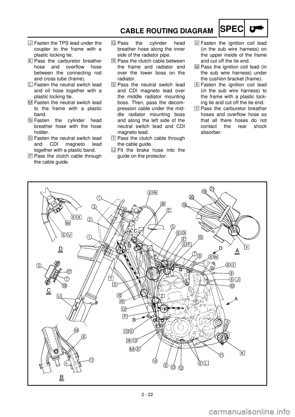
ïFasten the TPS lead under the
coupler to the frame with a
plastic locking tie.
ðPass the carburetor breather
hose and overflow hose
between the connecting rod
and cross tube (frame).
ñFasten the neutral switch lead
and oil hose together with a
plastic locking tie.
÷Fasten the neutral switch lead
to the frame with a plastic
band.
öFasten the cylinder head
breather hose with the hose
holder.
¯Fasten the neutral switch lead
and CDI magneto lead
together with a plastic band.
¸Pass the clutch cable through
the cable guide.ÎPass the cylinder head
breather hose along the inner
side of the radiator pipe.
åPass the clutch cable between
the frame and radiator and
over the lower boss on the
radiator.
êPass the neutral switch lead
and CDI magneto lead over
the middle radiator mounting
boss. Then, pass the decom-
pression cable under the mid-
dle radiator mounting boss
and along the left side of the
neutral switch lead and CDI
magneto lead.
æPass the clutch cable through
the cable guide.
èFit the brake hose into the
guide on the protector.×Fasten the ignition coil lead
(in the sub wire harness) on
the upper inside of the frame
and cut off the tie end.
ãPass the ignition coil lead (in
the sub wire harness) under
the cushion bracket (frame).
ÅFasten the ignition coil lead
(in the sub wire harness) to
the frame with a plastic lock-
ing tie and cut off the tie end.
çPass the carburetor breather
hoses and overflow hose so
that all there hoses do not
contact the rear shock
absorber.
Page 152 of 654
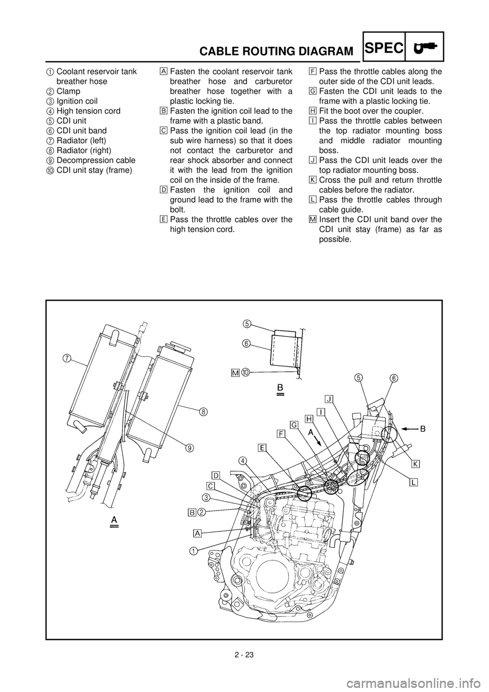
2 - 23
SPECCABLE ROUTING DIAGRAM
1Coolant reservoir tank
breather hose
2Clamp
3Ignition coil
4High tension cord
5CDI unit
6CDI unit band
7Radiator (left)
8Radiator (right)
9Decompression cable
0CDI unit stay (frame)Fasten the coolant reservoir tank
breather hose and carburetor
breather hose together with a
plastic locking tie.
õFasten the ignition coil lead to the
frame with a plastic band.
‚Pass the ignition coil lead (in the
sub wire harness) so that it does
not contact the carburetor and
rear shock absorber and connect
it with the lead from the ignition
coil on the inside of the frame.
ëFasten the ignition coil and
ground lead to the frame with the
bolt.
äPass the throttle cables over the
high tension cord.ìPass the throttle cables along the
outer side of the CDI unit leads.
íFasten the CDI unit leads to the
frame with a plastic locking tie.
îFit the boot over the coupler.
éPass the throttle cables between
the top radiator mounting boss
and middle radiator mounting
boss.
ïPass the CDI unit leads over the
top radiator mounting boss.
ðCross the pull and return throttle
cables before the radiator.
ñPass the throttle cables through
cable guide.
÷Insert the CDI unit band over the
CDI unit stay (frame) as far as
possible.
Page 172 of 654
3 - 5
INSP
ADJ
EC350000
ENGINE
EC351011
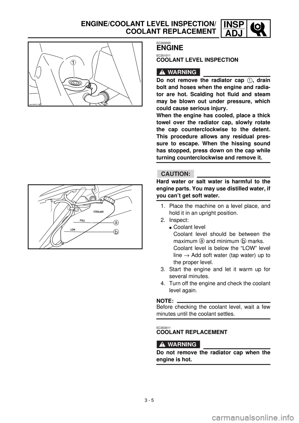
COOLANT LEVEL INSPECTION
WARNING
Do not remove the radiator cap
1
, drain
bolt and hoses when the engine and radia-
tor are hot. Scalding hot fluid and steam
may be blown out under pressure, which
could cause serious injury.
When the engine has cooled, place a thick
towel over the radiator cap, slowly rotate
the cap counterclockwise to the detent.
This procedure allows any residual pres-
sure to escape. When the hissing sound
has stopped, press down on the cap while
turning counterclockwise and remove it.
CAUTION:
Hard water or salt water is harmful to the
engine parts. You may use distilled water, if
you can’t get soft water.
1. Place the machine on a level place, and
hold it in an upright position.
2. Inspect:
l
Coolant level
Coolant level should be between the
maximum
a
and minimum
b
marks.
Coolant level is below the “LOW” level
line
®
Add soft water (tap water) up to
the proper level.
3. Start the engine and let it warm up for
several minutes.
4. Turn off the engine and check the coolant
level again.
NOTE:
Before checking the coolant level, wait a few
minutes until the coolant settles.
LOWFULLCOOLANT
a
b
EC353011
COOLANT REPLACEMENT
WARNING
Do not remove the radiator cap when the
engine is hot.
ENGINE/COOLANT LEVEL INSPECTION/
COOLANT REPLACEMENT