engine YAMAHA WR 400F 2000 Manual PDF
[x] Cancel search | Manufacturer: YAMAHA, Model Year: 2000, Model line: WR 400F, Model: YAMAHA WR 400F 2000Pages: 654, PDF Size: 60.12 MB
Page 388 of 654
ENG
4 - 63
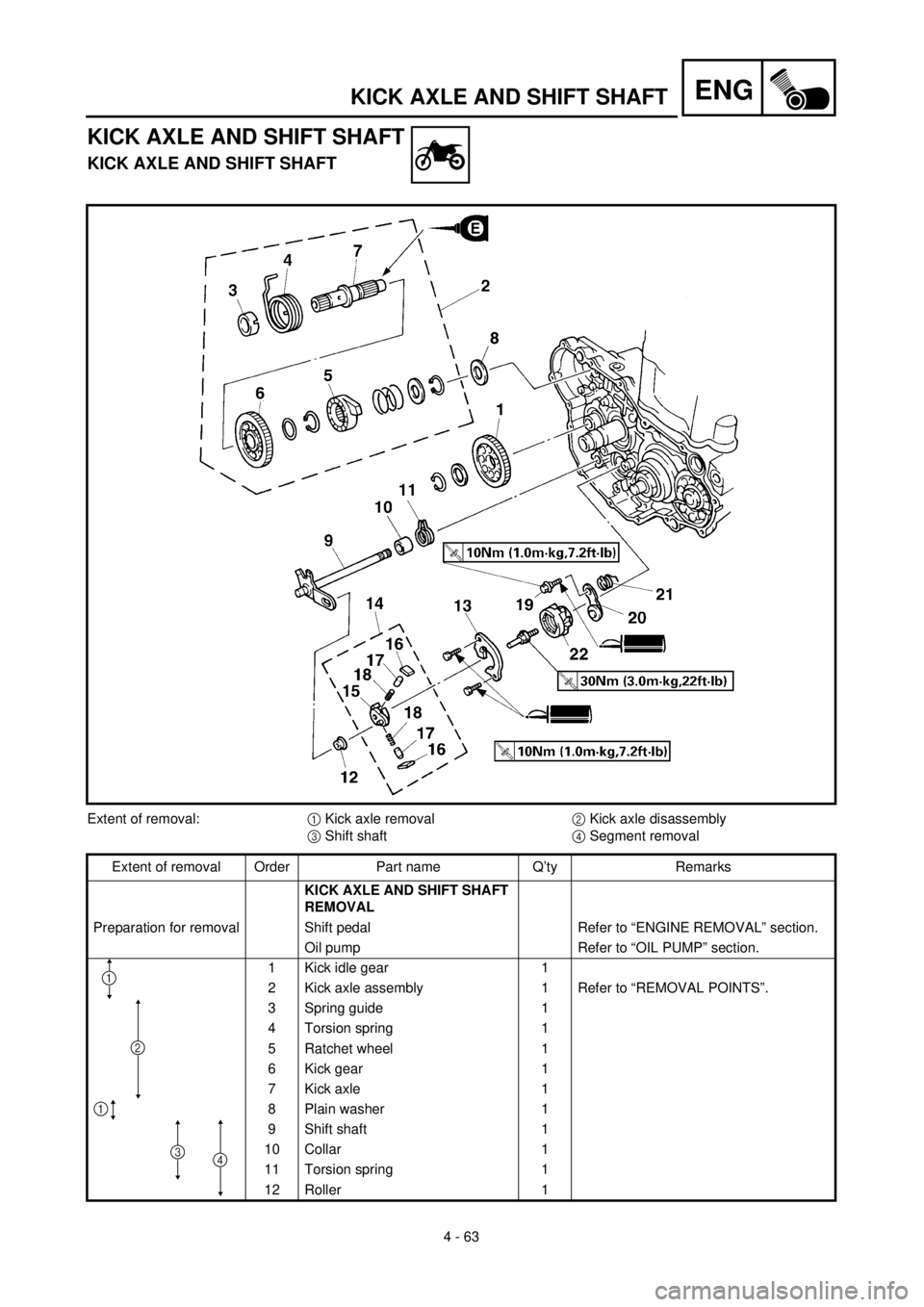
KICK AXLE AND SHIFT SHAFT
KICK AXLE AND SHIFT SHAFT
KICK AXLE AND SHIFT SHAFT
Extent of removal:
1 Kick axle removal2 Kick axle disassembly
3 Shift shaft4 Segment removal
Extent of removal Order Part name Q’ty Remarks
KICK AXLE AND SHIFT SHAFT
REMOVAL
Preparation for removal Shift pedal Refer to “ENGINE REMOVAL” section.
Oil pump Refer to “OIL PUMP” section.
1 Kick idle gear 1
2 Kick axle assembly 1 Refer to “REMOVAL POINTS”.
3 Spring guide 1
4 Torsion spring 1
5 Ratchet wheel 1
6 Kick gear 1
7 Kick axle 1
8 Plain washer 1
9 Shift shaft 1
10 Collar 1
11 Torsion spring 1
12 Roller 1
3
2
1
4
1
Page 396 of 654
4 - 67
ENGKICK AXLE AND SHIFT SHAFT
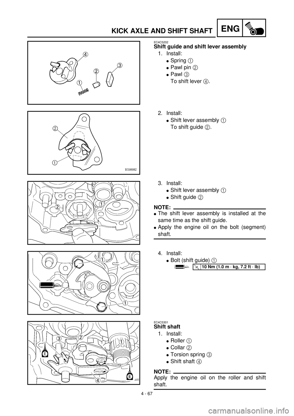
EC4C5202
Shift guide and shift lever assembly
1. Install:
lSpring 1
lPawl pin 2
lPawl 3
To shift lever 4.
2. Install:
lShift lever assembly 1
To shift guide 2.
3. Install:
lShift lever assembly 1
lShift guide 2
NOTE:
lThe shift lever assembly is installed at the
same time as the shift guide.
lApply the engine oil on the bolt (segment)
shaft.
4. Install:
lBolt (shift guide) 1
T R..10 Nm (1.0 m · kg, 7.2 ft · lb)
EC4C5301
Shift shaft
1. Install:
lRoller 1
lCollar 2
lTorsion spring 3
lShift shaft 4
NOTE:
Apply the engine oil on the roller and shift
shaft.
Page 398 of 654
4 - 68
ENGKICK AXLE AND SHIFT SHAFT
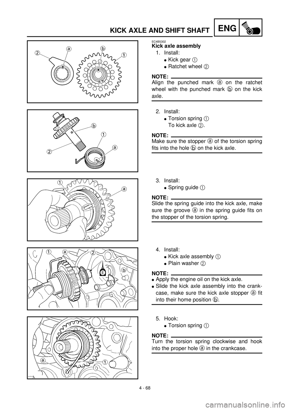
EC4B5302
Kick axle assembly
1. Install:
lKick gear 1
lRatchet wheel 2
NOTE:
Align the punched mark a on the ratchet
wheel with the punched mark b on the kick
axle.
2. Install:
lTorsion spring 1
To kick axle 2.
NOTE:
Make sure the stopper a of the torsion spring
fits into the hole b on the kick axle.
3. Install:
lSpring guide 1
NOTE:
Slide the spring guide into the kick axle, make
sure the groove a in the spring guide fits on
the stopper of the torsion spring.
4. Install:
lKick axle assembly 1
lPlain washer 2
NOTE:
lApply the engine oil on the kick axle.
lSlide the kick axle assembly into the crank-
case, make sure the kick axle stopper a fit
into their home position b.
5. Hook:
lTorsion spring 1
NOTE:
Turn the torsion spring clockwise and hook
into the proper hole a in the crankcase.
Page 400 of 654
4 - 69
ENGKICK AXLE AND SHIFT SHAFT
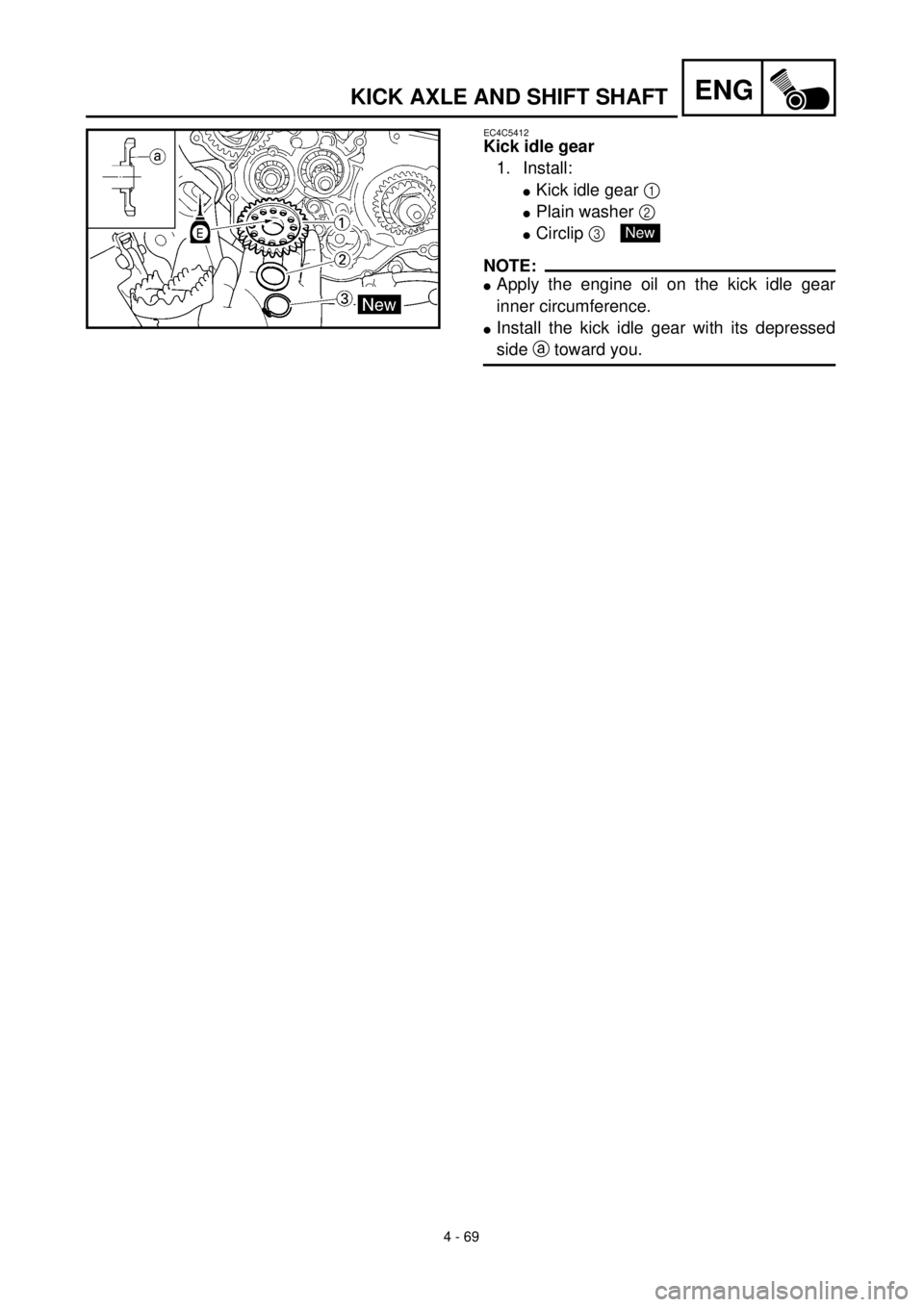
EC4C5412
Kick idle gear
1. Install:
lKick idle gear 1
lPlain washer 2
lCirclip 3
NOTE:
lApply the engine oil on the kick idle gear
inner circumference.
lInstall the kick idle gear with its depressed
side a toward you.
New
Page 410 of 654
ENG
4 - 74
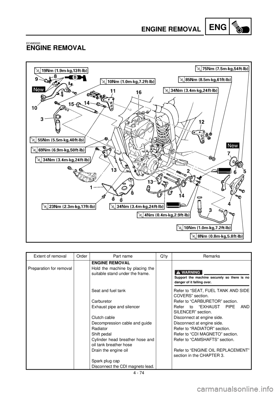
ENGINE REMOVAL
EC4M0000
ENGINE REMOVAL
Extent of removal Order Part name Q’ty Remarks
ENGINE REMOVAL
Preparation for removal Hold the machine by placing the
suitable stand under the frame.
Seat and fuel tank Refer to “SEAT, FUEL TANK AND SIDE
COVERS” section.
Carburetor Refer to “CARBURETOR” section.
Exhaust pipe and silencer Refer to “EXHAUST PIPE AND
SILENCER” section.
Clutch cable Disconnect at engine side.
Decompression cable and guide Disconnect at engine side.
Radiator Refer to “RADIATOR” section.
Shift pedal Refer to “CDI MAGNETO” section.
Cylinder head breather hose and
oil tank breather hoseRefer to “CAMSHAFTS” section.
Drain the engine oil Refer to “ENGINE OIL REPLACEMENT”
section in the CHAPTER 3.
Spark plug cap
Disconnect the CDI magneto lead.
WARNING
Support the machine securely so there is nodanger of it falling over.
Page 412 of 654
ENG
4 - 75
ENGINE REMOVAL
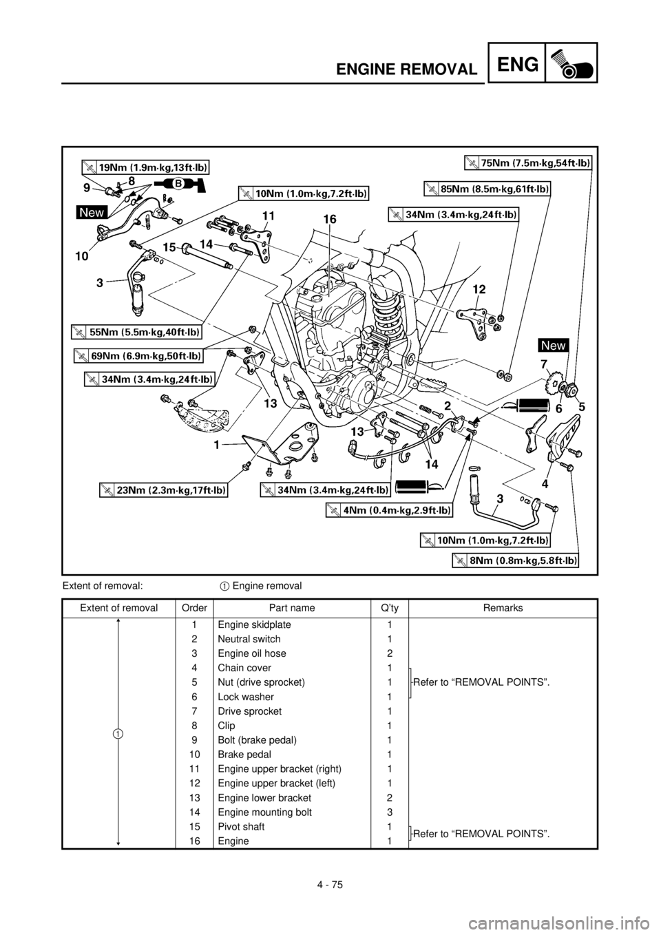
Extent of removal:1 Engine removal
Extent of removal Order Part name Q’ty Remarks
1 Engine skidplate 1
2 Neutral switch 1
3 Engine oil hose 2
4 Chain cover 1
Refer to “REMOVAL POINTS”. 5 Nut (drive sprocket) 1
6 Lock washer 1
7 Drive sprocket 1
8 Clip 1
9 Bolt (brake pedal) 1
10 Brake pedal 1
11 Engine upper bracket (right) 1
12 Engine upper bracket (left) 1
13 Engine lower bracket 2
14 Engine mounting bolt 3
15 Pivot shaft 1
Refer to “REMOVAL POINTS”.
16 Engine 1
1
Page 414 of 654
4 - 76
ENGENGINE REMOVAL
EC4M3000
REMOVAL POINTS
EC4F3100
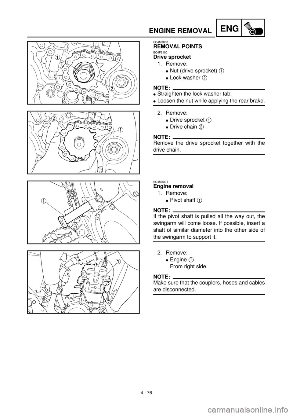
Drive sprocket
1. Remove:
lNut (drive sprocket) 1
lLock washer 2
NOTE:
lStraighten the lock washer tab.
lLoosen the nut while applying the rear brake.
2. Remove:
lDrive sprocket 1
lDrive chain 2
NOTE:
Remove the drive sprocket together with the
drive chain.
EC4M3301
Engine removal
1. Remove:
lPivot shaft 1
NOTE:
If the pivot shaft is pulled all the way out, the
swingarm will come loose. If possible, insert a
shaft of similar diameter into the other side of
the swingarm to support it.
2. Remove:
lEngine 1
From right side.
NOTE:
Make sure that the couplers, hoses and cables
are disconnected.
Page 416 of 654
4 - 77
ENGENGINE REMOVAL
EC4M5000
ASSEMBLY AND INSTALLATION
EC4M5160
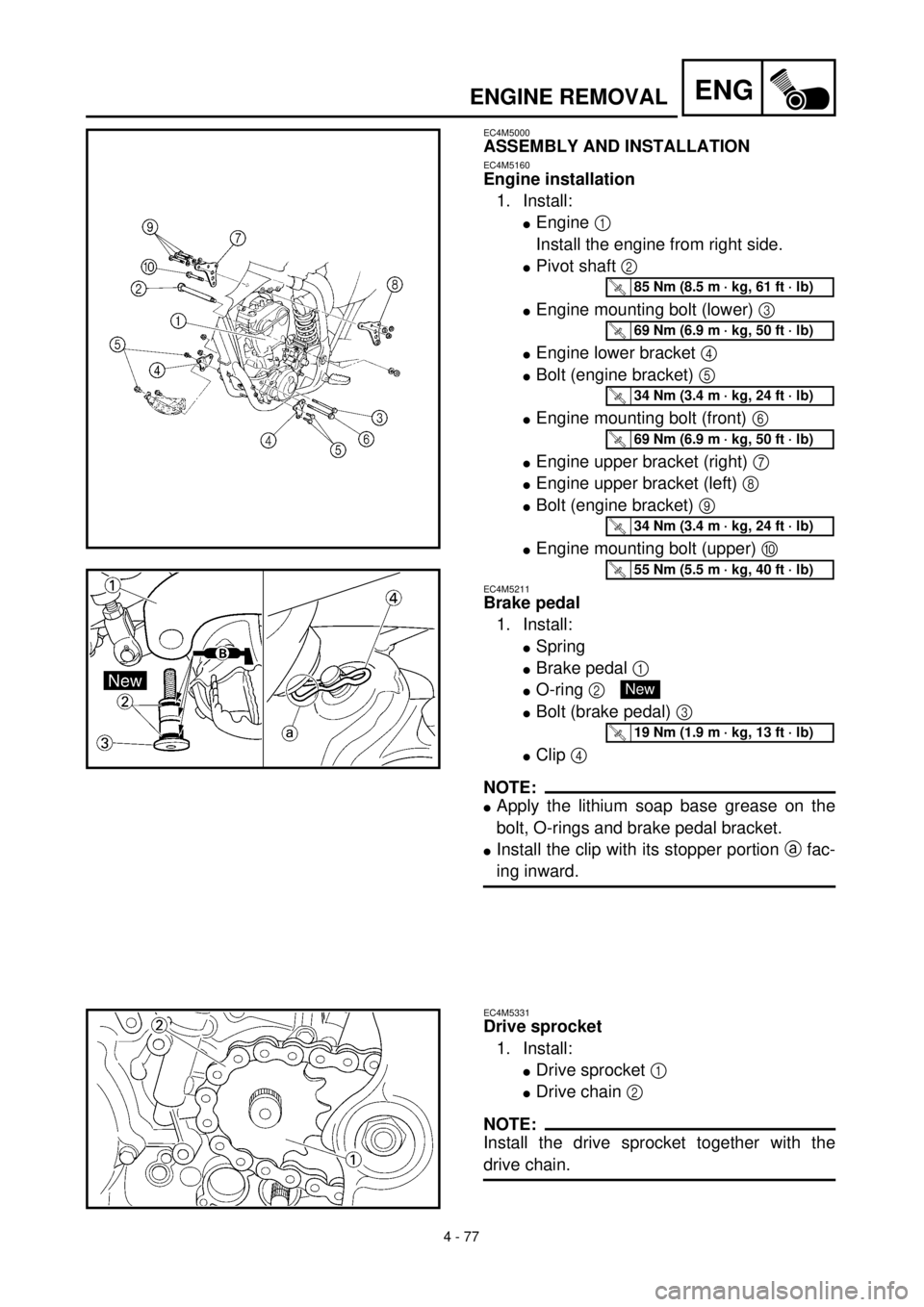
Engine installation
1. Install:
lEngine 1
Install the engine from right side.
lPivot shaft 2
lEngine mounting bolt (lower) 3
lEngine lower bracket 4
lBolt (engine bracket) 5
lEngine mounting bolt (front) 6
lEngine upper bracket (right) 7
lEngine upper bracket (left) 8
lBolt (engine bracket) 9
lEngine mounting bolt (upper) 0
EC4M5211
Brake pedal
1. Install:
lSpring
lBrake pedal 1
lO-ring 2
lBolt (brake pedal) 3
lClip 4
NOTE:
lApply the lithium soap base grease on the
bolt, O-rings and brake pedal bracket.
lInstall the clip with its stopper portion a fac-
ing inward.
T R..85 Nm (8.5 m · kg, 61 ft · lb)
T R..69 Nm (6.9 m · kg, 50 ft · lb)
T R..34 Nm (3.4 m · kg, 24 ft · lb)
T R..69 Nm (6.9 m · kg, 50 ft · lb)
T R..34 Nm (3.4 m · kg, 24 ft · lb)
T R..55 Nm (5.5 m · kg, 40 ft · lb)
New
T R..19 Nm (1.9 m · kg, 13 ft · lb)
EC4M5331
Drive sprocket
1. Install:
lDrive sprocket 1
lDrive chain 2
NOTE:
Install the drive sprocket together with the
drive chain.
Page 418 of 654
4 - 78
ENGENGINE REMOVAL
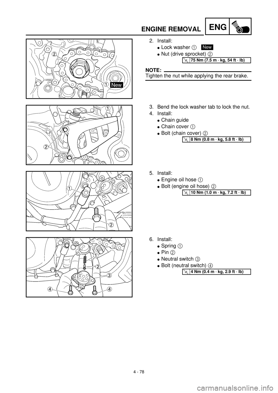
2. Install:
lLock washer 1
lNut (drive sprocket) 2
NOTE:
Tighten the nut while applying the rear brake.
New
T R..75 Nm (7.5 m · kg, 54 ft · lb)
3. Bend the lock washer tab to lock the nut.
4. Install:
lChain guide
lChain cover 1
lBolt (chain cover) 2
T R..8 Nm (0.8 m · kg, 5.8 ft · lb)
5. Install:
lEngine oil hose 1
lBolt (engine oil hose) 2
T R..10 Nm (1.0 m · kg, 7.2 ft · lb)
6. Install:
lSpring 1
lPin 2
lNeutral switch 3
lBolt (neutral switch) 4
T R..4 Nm (0.4 m · kg, 2.9 ft · lb)
Page 420 of 654
ENG
4 - 79
CRANKCASE AND CRANKSHAFT
CRANKCASE AND CRANKSHAFT
CRANKCASE AND CRANKSHAFT
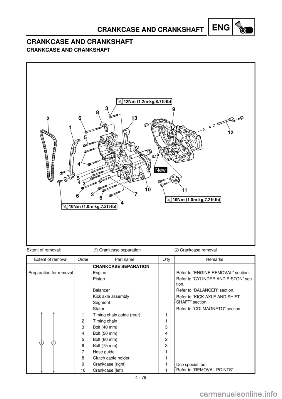
Extent of removal:1 Crankcase separation2 Crankcase removal
Extent of removal Order Part name Q’ty Remarks
CRANKCASE SEPARATION
Preparation for removal Engine Refer to “ENGINE REMOVAL” section.
Piston Refer to “CYLINDER AND PISTON” sec-
tion.
Balancer Refer to “BALANCER” section.
Kick axle assembly
Refer to “KICK AXLE AND SHIFT
SHAFT” section.
Segment
Stator Refer to “CDI MAGNETO” section.
1 Timing chain guide (rear) 1
2 Timing chain 1
3 Bolt (40 mm) 3
4 Bolt (50 mm) 4
5 Bolt (60 mm) 2
6 Bolt (75 mm) 3
7 Hose guide 1
8 Clutch cable holder 1
9 Crankcase (right) 1
Use special tool.
Refer to “REMOVAL POINTS”.
10 Crankcase (left) 1
21