fuel tank removal YAMAHA WR 400F 2000 Owners Manual
[x] Cancel search | Manufacturer: YAMAHA, Model Year: 2000, Model line: WR 400F, Model: YAMAHA WR 400F 2000Pages: 654, PDF Size: 60.12 MB
Page 22 of 654

CHAPTER 4
ENGINE
SEAT, FUEL TANK AND
SIDE COVERS
...........................................4-1
EXHAUST PIPE AND SILENCER
.............4-2
RADIATOR
................................................4-3
CARBURETOR
..........................................4-7
CAMSHAFTS
...........................................4-20
CYLINDER HEAD
....................................4-27
VALVES AND VALVE SPRINGS
............4-30
CYLINDER AND PISTON
........................4-38
CLUTCH
...................................................4-44
OIL FILTER, WATER PUMP AND
CRANKCASE COVER (RIGHT)
..............4-50
BALANCER
.............................................4-56
OIL PUMP
................................................4-59
KICK AXLE AND SHIFT SHAFT
.............4-63
CDI MAGNETO
........................................4-70
ENGINE REMOVAL
.................................4-74
CRANKCASE AND CRANKSHAFT
........4-79
TRANSMISSION, SHIFT CAM AND
SHIFT FORK
............................................4-88
CHAPTER 5
CHASSIS
FRONT WHEEL AND REAR WHEEL
.......5-1
FRONT BRAKE AND REAR BRAKE
.....5-10
FRONT FORK
..........................................5-27
HANDLEBAR
...........................................5-40
STEERING
...............................................5-45
SWINGARM
.............................................5-51
REAR SHOCK ABSORBER
....................5-58
Page 264 of 654
ENG
4 - 1
3EC400000
ENGINE
EC4R0000
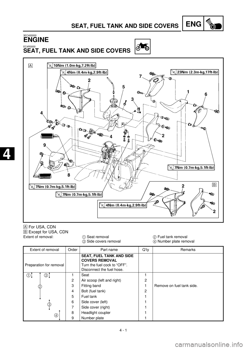
SEAT, FUEL TANK AND SIDE COVERS
SEAT, FUEL TANK AND SIDE COVERS
For USA, CDN
õ
Except for USA, CDN
Extent of removal:
1
Seat removal
2
Fuel tank removal
3
Side covers removal
4
Number plate removal
Extent of removal Order Part name Q’ty Remarks
Preparation for removal
SEAT, FUEL TANK AND SIDE
COVERS REMOVAL
Turn the fuel cock to “OFF”.
Disconnect the fuel hose.
1 Seat 1
2 Air scoop (left and right) 2
3 Fitting band 1 Remove on fuel tank side.
4 Bolt (fuel tank) 2
5 Fuel tank 1
6 Side cover (left) 1
7 Side cover (right) 1
8 Headlight coupler 1
9 Number plate 1
13
4
2
3
4
Page 266 of 654
ENG
4 - 2
EXHAUST PIPE AND SILENCER
EC4S0000
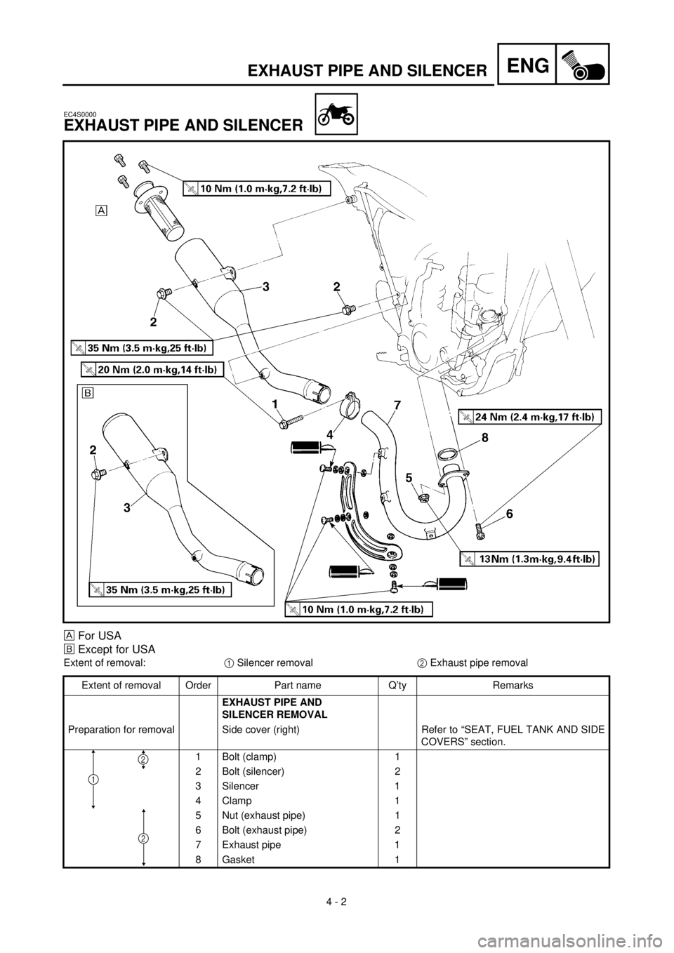
EXHAUST PIPE AND SILENCER
For USA
õ
Except for USA
Extent of removal:
1
Silencer removal
2
Exhaust pipe removal
Extent of removal Order Part name Q’ty Remarks
EXHAUST PIPE AND
SILENCER REMOVAL
Preparation for removal Side cover (right) Refer to “SEAT, FUEL TANK AND SIDE
COVERS” section.
1 Bolt (clamp) 1
2 Bolt (silencer) 2
3 Silencer 1
4 Clamp 1
5 Nut (exhaust pipe) 1
6 Bolt (exhaust pipe) 2
7 Exhaust pipe 1
8Gasket
1
2
1
2
Page 268 of 654
ENG
4 - 3
RADIATOR
EC450001
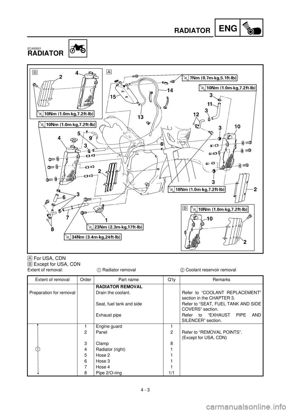
RADIATOR
For USA, CDN
õ
Except for USA, CDN
Extent of removal:
1
Radiator removal
2
Coolant reservoir removal
Extent of removal Order Part name Q’ty Remarks
RADIATOR REMOVAL
Preparation for removal Drain the coolant. Refer to “COOLANT REPLACEMENT”
section in the CHAPTER 3.
Seat, fuel tank and side Refer to “SEAT, FUEL TANK AND SIDE
COVERS” section.
Exhaust pipe Refer to “EXHAUST PIPE AND
SILENCER” section.
1 Engine guard 1
2 Panel 2 Refer to “REMOVAL POINTS”.
(Except for USA, CDN)
3 Clamp 8
4 Radiator (right) 1
5 Hose 2 1
6 Hose 3 1
7 Hose 4 1
8 Pipe 2/O-ring 1/1
1
Page 276 of 654
ENG
4 - 7
CARBURETOR
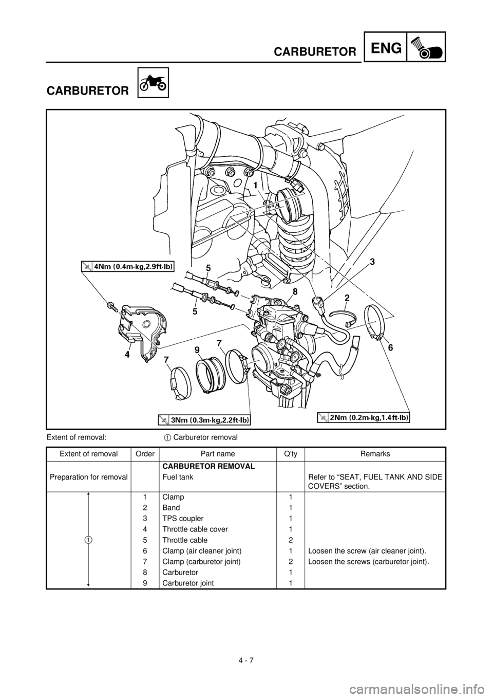
CARBURETOR
Extent of removal:1 Carburetor removal
Extent of removal Order Part name Q’ty Remarks
CARBURETOR REMOVAL
Preparation for removal Fuel tank Refer to “SEAT, FUEL TANK AND SIDE
COVERS” section.
1 Clamp 1
2 Band 1
3 TPS coupler 1
4 Throttle cable cover 1
5 Throttle cable 2
6 Clamp (air cleaner joint) 1 Loosen the screw (air cleaner joint).
7 Clamp (carburetor joint) 2 Loosen the screws (carburetor joint).
8 Carburetor 1
9 Carburetor joint 1
1
Page 302 of 654
ENG
4 - 20
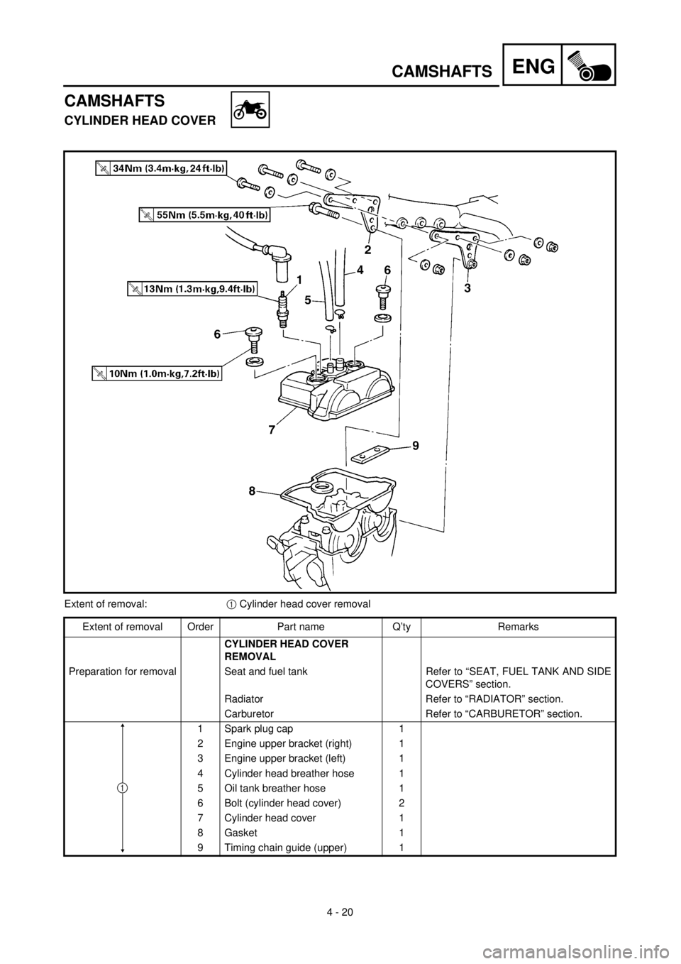
CAMSHAFTS
CAMSHAFTS
CYLINDER HEAD COVER
Extent of removal:1 Cylinder head cover removal
Extent of removal Order Part name Q’ty Remarks
CYLINDER HEAD COVER
REMOVAL
Preparation for removal Seat and fuel tank Refer to “SEAT, FUEL TANK AND SIDE
COVERS” section.
Radiator Refer to “RADIATOR” section.
Carburetor Refer to “CARBURETOR” section.
1 Spark plug cap 1
2 Engine upper bracket (right) 1
3 Engine upper bracket (left) 1
4 Cylinder head breather hose 1
5 Oil tank breather hose 1
6 Bolt (cylinder head cover) 2
7 Cylinder head cover 1
8 Gasket 1
9 Timing chain guide (upper) 1
1
Page 316 of 654
ENG
4 - 27
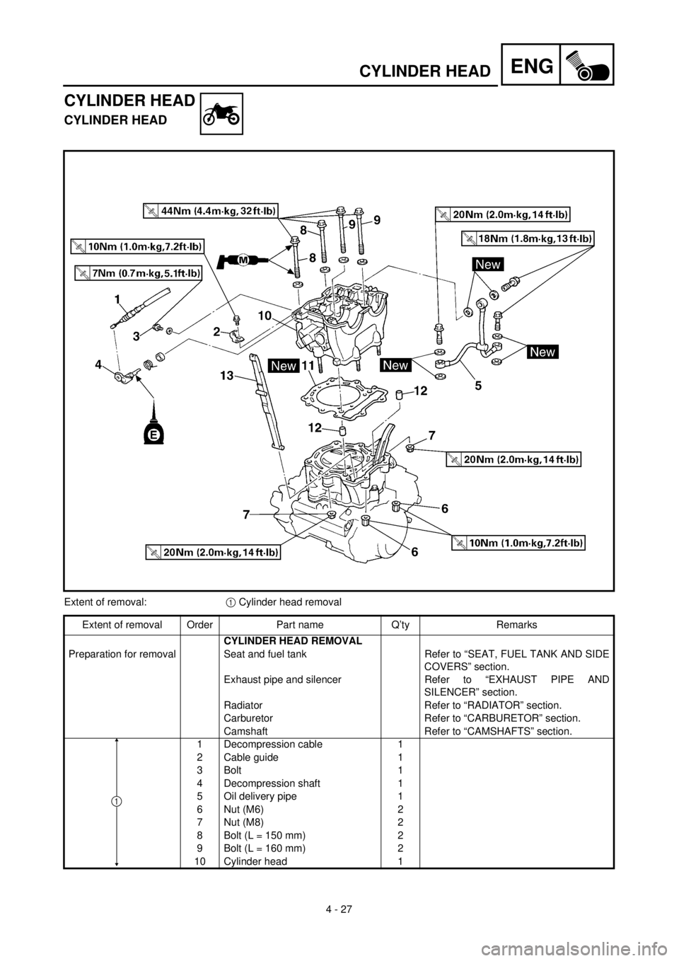
CYLINDER HEAD
CYLINDER HEAD
CYLINDER HEAD
Extent of removal:1 Cylinder head removal
Extent of removal Order Part name Q’ty Remarks
CYLINDER HEAD REMOVAL
Preparation for removal Seat and fuel tank Refer to “SEAT, FUEL TANK AND SIDE
COVERS” section.
Exhaust pipe and silencer Refer to “EXHAUST PIPE AND
SILENCER” section.
Radiator Refer to “RADIATOR” section.
Carburetor Refer to “CARBURETOR” section.
Camshaft Refer to “CAMSHAFTS” section.
1 Decompression cable 1
2 Cable guide 1
3 Bolt 1
4 Decompression shaft 1
5 Oil delivery pipe 1
6 Nut (M6) 2
7 Nut (M8) 2
8 Bolt (L = 150 mm) 2
9 Bolt (L = 160 mm) 2
10 Cylinder head 1
1
Page 402 of 654
ENG
4 - 70
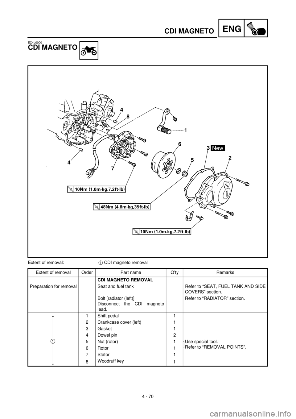
CDI MAGNETO
EC4L0000
CDI MAGNETO
Extent of removal:1 CDI magneto removal
Extent of removal Order Part name Q’ty Remarks
CDI MAGNETO REMOVAL
Preparation for removal Seat and fuel tank Refer to “SEAT, FUEL TANK AND SIDE
COVERS” section.
Bolt [radiator (left)]
Disconnect the CDI magneto
lead.Refer to “RADIATOR” section.
1 Shift pedal 1
2 Crankcase cover (left) 1
3 Gasket 1
4 Dowel pin 2
5 Nut (rotor) 1 Use special tool.
Refer to “REMOVAL POINTS”.
6 Rotor 1
7 Stator 1
8Woodruff key
1
1
Page 410 of 654
ENG
4 - 74
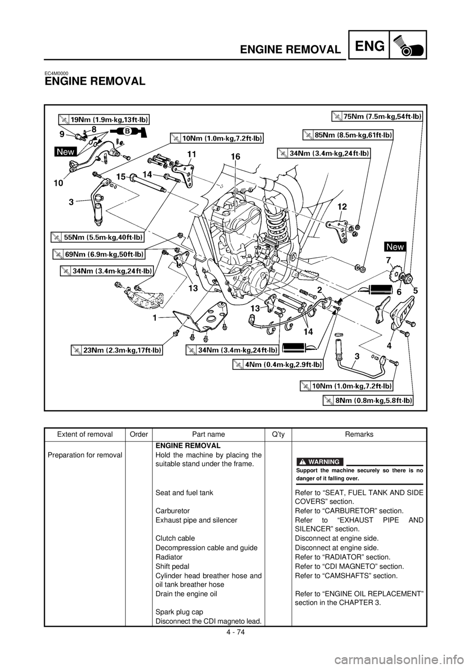
ENGINE REMOVAL
EC4M0000
ENGINE REMOVAL
Extent of removal Order Part name Q’ty Remarks
ENGINE REMOVAL
Preparation for removal Hold the machine by placing the
suitable stand under the frame.
Seat and fuel tank Refer to “SEAT, FUEL TANK AND SIDE
COVERS” section.
Carburetor Refer to “CARBURETOR” section.
Exhaust pipe and silencer Refer to “EXHAUST PIPE AND
SILENCER” section.
Clutch cable Disconnect at engine side.
Decompression cable and guide Disconnect at engine side.
Radiator Refer to “RADIATOR” section.
Shift pedal Refer to “CDI MAGNETO” section.
Cylinder head breather hose and
oil tank breather hoseRefer to “CAMSHAFTS” section.
Drain the engine oil Refer to “ENGINE OIL REPLACEMENT”
section in the CHAPTER 3.
Spark plug cap
Disconnect the CDI magneto lead.
WARNING
Support the machine securely so there is nodanger of it falling over.
Page 562 of 654

5 - 58
CHASREAR SHOCK ABSORBER
EC580000
REAR SHOCK ABSORBER
Extent of removal:1 Rear shock absorber removal2 Rear shock absorber disassembly
Extent of removal Order Part name Q’ty Remarks
Preparation for removalREAR SHOCK ABSORBER
REMOVAL
Hold the machine by placing the
suitable stand under the engine.
Seat, fitting band and side covers Refer to “SEAT, FUEL TANK AND SIDE
COVERS” section in the CHAPTER 4.
Silencer Refer to “EXHAUST PIPE AND
SILENCER” section in the CHAPTER 4.
Drain the coolant. Refer to “COOLANT REPLACENENTR ”
section in the CHAPTER 3.
Coolant reservoir Refer to “RADIATOR” section in the
CHAPTER 4.
1 Tail light connector 2
2 Band 2
3 Bolt (brake reservoir tank) 1
4 Clamp (air cleaner joint) 1 Only loosening.
5 Rear frame 1
6 Bolt (rear shock absorber-relay arm) 1Hold the swingarm.
7 Bolt (rear shock absorber-frame) 1
8 Rear shock absorber 1
WARNING
Support the machine securely so there is nodanger of it falling over.
1
2