ignition YAMAHA WR 400F 2000 Owners Manual
[x] Cancel search | Manufacturer: YAMAHA, Model Year: 2000, Model line: WR 400F, Model: YAMAHA WR 400F 2000Pages: 654, PDF Size: 60.12 MB
Page 24 of 654

CHAPTER 6
ELECTRICAL
ELECTRICAL COMPONENTS AND
WIRING DIAGRAM
....................................6-1
MAP-CONTROLLED CDI UNIT
.................6-2
IGNITION SYSTEM
....................................6-3
TPS (THROTTLE POSITION SENSOR)
SYSTEM
.....................................................6-7
LIGHTING SYSTEM
................................6-11
CHAPTER 7
TUNING
ENGINE
......................................................7-1
CHASSIS
.................................................7-10
Page 37 of 654
1 - 7
GEN
INFO
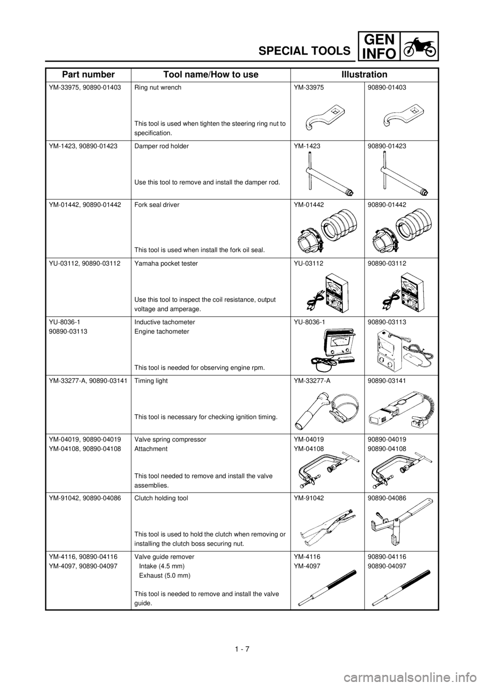
SPECIAL TOOLS
YM-33975, 90890-01403 Ring nut wrench
This tool is used when tighten the steering ring nut to
specification.YM-33975 90890-01403
YM-1423, 90890-01423 Damper rod holder
Use this tool to remove and install the damper rod.YM-1423 90890-01423
YM-01442, 90890-01442 Fork seal driver
This tool is used when install the fork oil seal.YM-01442 90890-01442
YU-03112, 90890-03112 Yamaha pocket tester
Use this tool to inspect the coil resistance, output
voltage and amperage.YU-03112 90890-03112
YU-8036-1
90890-03113Inductive tachometer
Engine tachometer
This tool is needed for observing engine rpm.YU-8036-1 90890-03113
YM-33277-A, 90890-03141 Timing light
This tool is necessary for checking ignition timing.YM-33277-A 90890-03141
YM-04019, 90890-04019
YM-04108, 90890-04108Valve spring compressor
Attachment
This tool needed to remove and install the valve
assemblies.YM-04019
YM-0410890890-04019
90890-04108
YM-91042, 90890-04086 Clutch holding tool
This tool is used to hold the clutch when removing or
installing the clutch boss securing nut.YM-91042 90890-04086
YM-4116, 90890-04116
YM-4097, 90890-04097Valve guide remover
Intake (4.5 mm)
Exhaust (5.0 mm)
This tool is needed to remove and install the valve
guide.YM-4116
YM-409790890-04116
90890-04097
Part number Tool name/How to use Illustration
Page 38 of 654
1 - 8
GEN
INFO
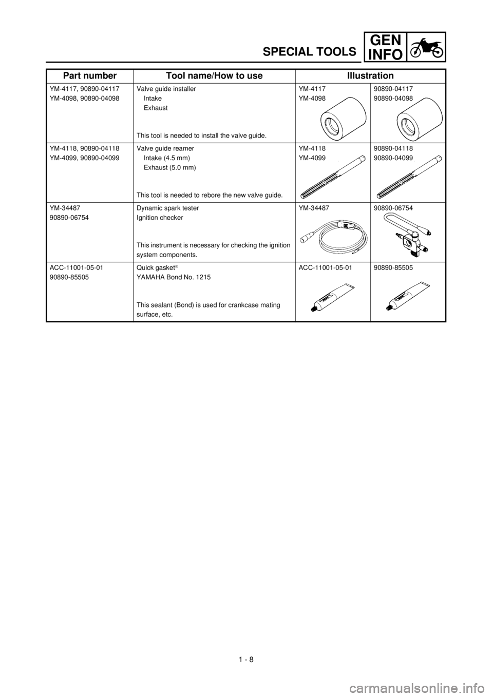
SPECIAL TOOLS
YM-4117, 90890-04117
YM-4098, 90890-04098Valve guide installer
Intake
Exhaust
This tool is needed to install the valve guide.YM-4117
YM-409890890-04117
90890-04098
YM-4118, 90890-04118
YM-4099, 90890-04099Valve guide reamer
Intake (4.5 mm)
Exhaust (5.0 mm)
This tool is needed to rebore the new valve guide.YM-4118
YM-409990890-04118
90890-04099
YM-34487
90890-06754Dynamic spark tester
Ignition checker
This instrument is necessary for checking the ignition
system components.YM-34487 90890-06754
ACC-11001-05-01
90890-85505Quick gasket
â
YAMAHA Bond No. 1215
This sealant (Bond) is used for crankcase mating
surface, etc.ACC-11001-05-01 90890-85505
Part number Tool name/How to use Illustration
Page 74 of 654

2 - 3
SPEC
GENERAL SPECIFICATIONS
Tire:
Type With tube
Size (front) 80/100-21 51M (USA, CDN, ZA)
90/90-21 54R (EUROPE, AUS, NZ)
Size (rear) 110/100-18 64M (USA, CDN, ZA)
120/90-18 65R (EUROPE, AUS, NZ)
Tire pressure (front and rear) 100 kPa (1.0 kg/cm
2
, 15 psi)
Brake:
Front brake type Single disc brake
Operation Right hand operation
Rear brake type Single disc brake
Operation Right foot operation
Suspension:
Front suspension Telescopic fork
Rear suspension Swingarm (link type monocross suspension)
Shock absorber:
Front shock absorber Coil spring/oil damper
Rear shock absorber Coil spring/gas, oil damper
Wheel travel:
Front wheel travel 300 mm (11.8 in)
Rear wheel travel 315 mm (12.4 in)
Electrical:
Ignition system CDI magneto
Page 88 of 654

2 - 17
SPECMAINTENANCE SPECIFICATIONS
EC212300
ELECTRICAL
Item Standard Limit
Ignition system:
Advancer type Electrical ----
C.D.I.:
Magneto-model/manufacturer F5BF/YAMAHA ----
Source coil 1 resistance (color) 640 ~ 960 W at 20 ˚C (68 ˚F)
(Green – Brown)----
Source coil 2 resistance (color) 464 ~ 696 W at 20 ˚C (68 ˚F)
(Green – Pink)----
Lighting coil resistance (color) 0.16 ~ 0.24 W at 20 ˚C (68 ˚F)
(Black – Yellow)
Pickup coil resistance (color) 248 ~ 372 W at 20 ˚C (68 ˚F)
(White – Red)----
CDI unit-model/manufacturer 5GS/YAMAHA ----
Ignition coil:
Model/manufacturer JF2/YAMAHA ----
Minimum spark gap 6 mm (0.24 in) ----
Primary winding resistance 0.20 ~ 0.30 W at 20 ˚C (68 ˚F) ----
Secondary winding resistance 9.5 ~ 14.3 kW at 20 ˚C (68 ˚F) ----
Part to be tightened Thread size Q’tyTightening torque
Nm m·kg ft·lb
Stator M6 ´ 1.0 3 10 1.0 7.2
Rotor M10 ´ 1.25 1 48 4.8 35
Ignition coil M6 ´ 1.0 2 7 0.7 5.1
Page 150 of 654
2 - 22
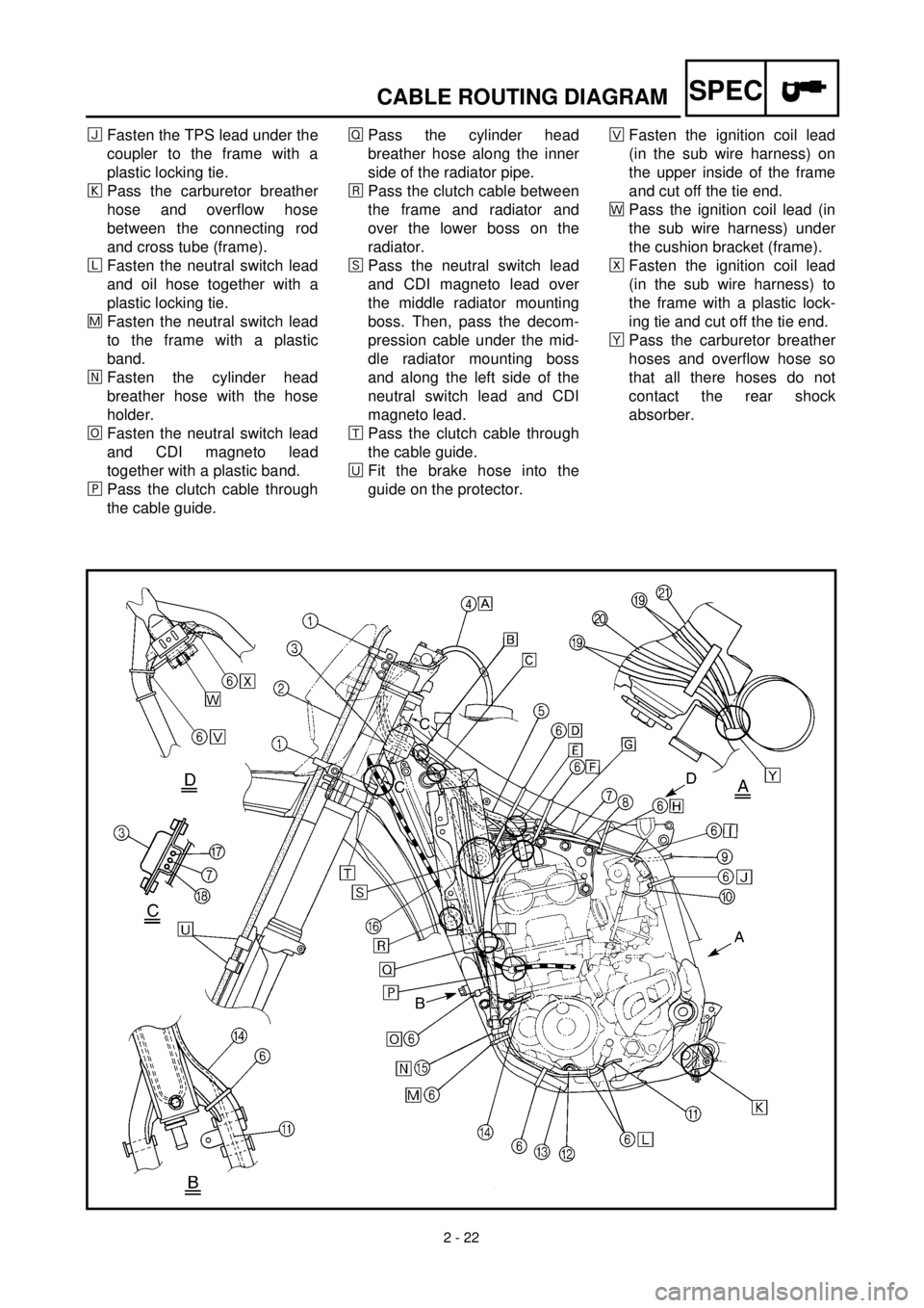
SPECCABLE ROUTING DIAGRAM
ïFasten the TPS lead under the
coupler to the frame with a
plastic locking tie.
ðPass the carburetor breather
hose and overflow hose
between the connecting rod
and cross tube (frame).
ñFasten the neutral switch lead
and oil hose together with a
plastic locking tie.
÷Fasten the neutral switch lead
to the frame with a plastic
band.
öFasten the cylinder head
breather hose with the hose
holder.
¯Fasten the neutral switch lead
and CDI magneto lead
together with a plastic band.
¸Pass the clutch cable through
the cable guide.ÎPass the cylinder head
breather hose along the inner
side of the radiator pipe.
åPass the clutch cable between
the frame and radiator and
over the lower boss on the
radiator.
êPass the neutral switch lead
and CDI magneto lead over
the middle radiator mounting
boss. Then, pass the decom-
pression cable under the mid-
dle radiator mounting boss
and along the left side of the
neutral switch lead and CDI
magneto lead.
æPass the clutch cable through
the cable guide.
èFit the brake hose into the
guide on the protector.×Fasten the ignition coil lead
(in the sub wire harness) on
the upper inside of the frame
and cut off the tie end.
ãPass the ignition coil lead (in
the sub wire harness) under
the cushion bracket (frame).
ÅFasten the ignition coil lead
(in the sub wire harness) to
the frame with a plastic lock-
ing tie and cut off the tie end.
çPass the carburetor breather
hoses and overflow hose so
that all there hoses do not
contact the rear shock
absorber.
Page 152 of 654
2 - 23
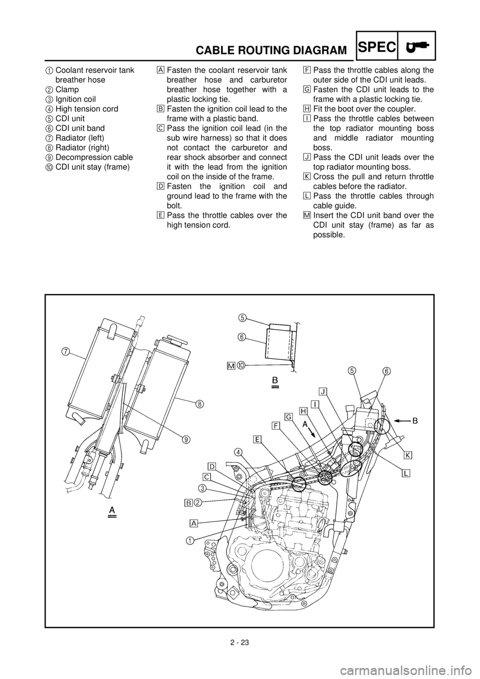
SPECCABLE ROUTING DIAGRAM
1Coolant reservoir tank
breather hose
2Clamp
3Ignition coil
4High tension cord
5CDI unit
6CDI unit band
7Radiator (left)
8Radiator (right)
9Decompression cable
0CDI unit stay (frame)Fasten the coolant reservoir tank
breather hose and carburetor
breather hose together with a
plastic locking tie.
õFasten the ignition coil lead to the
frame with a plastic band.
‚Pass the ignition coil lead (in the
sub wire harness) so that it does
not contact the carburetor and
rear shock absorber and connect
it with the lead from the ignition
coil on the inside of the frame.
ëFasten the ignition coil and
ground lead to the frame with the
bolt.
äPass the throttle cables over the
high tension cord.ìPass the throttle cables along the
outer side of the CDI unit leads.
íFasten the CDI unit leads to the
frame with a plastic locking tie.
îFit the boot over the coupler.
éPass the throttle cables between
the top radiator mounting boss
and middle radiator mounting
boss.
ïPass the CDI unit leads over the
top radiator mounting boss.
ðCross the pull and return throttle
cables before the radiator.
ñPass the throttle cables through
cable guide.
÷Insert the CDI unit band over the
CDI unit stay (frame) as far as
possible.
Page 168 of 654

3 - 4
INSP
ADJ
PRE-OPERATION INSPECTION AND MAINTENANCE
EC320000
PRE-OPERATION INSPECTION AND MAINTENANCE
Before riding for break-in operation, practice or a race, make sure the machine is in good operating
condition.
Before using this machine, check the following points.
GENERAL INSPECTION AND MAINTENANCE
Item Routine Page
CoolantCheck that coolant is filled up to the radiator filler cap.
Check that the coolant level is correct in the coolant reservoir
tank.
Check the cooling system for leakage.P.3-5 ~ 9
FuelCheck that a fresh gasoline is filled in the fuel tank. Check the
fuel line for leakage.P.1-12
Engine oilCheck that the oil level is correct. Check the crankcase and
frame oil line for leakage.P.3-13 ~ 17
Gear shifter and clutchCheck that gears can be shifted correctly in order and that the
clutch operates smoothly.P.3-9
Throttle grip/HousingCheck that the throttle grip operation and free play are correctly
adjusted. Lubricate the throttle grip and housing, if necessary.P.3-10 ~ 11
Brakes Check the play of front brake and effect of front and rear brake. P.3-25 ~ 31
ChainCheck chain slack and alignment. Check that the chain is lubri-
cated properly.P.3-32 ~ 34
WheelsCheck for excessive wear and tire pressure. Check for loose
spokes and have no excessive play.P.3-42 ~ 43
SteeringCheck that the handlebar can be turned smoothly and have no
excessive play.P.3-43 ~ 44
Front forks and rear shock
absorberCheck that they operate smoothly and there is no oil leakage. P.3-34 ~ 41
Cables (wires)Check that the clutch and throttle cables move smoothly. Check
that they are not caught when the handlebars are turned or
when the front forks travel up and down.—
Muffler Check that the muffler is tightly mounted and has no cracks. P.4-2
Sprocket Check that the driven sprocket tightening bolt is not loose. P.3-32
Lubrication Check for smooth operation. Lubricate if necessary. P.3-45
Bolts and nuts Check the chassis and engine for loose bolts and nuts. P.1-17
Lead connectorsCheck that the CDI magneto, CDI unit, and ignition coil are con-
nected tightly.P.1-5
SettingsIs the machine set suitably for the condition of the racing course
and weather or by taking into account the results of test runs
before racing? Are inspection and maintenance completely
done?P.7-1 ~ 21
Page 258 of 654
3 - 47
INSP
ADJ
IGNITION TIMING CHECK
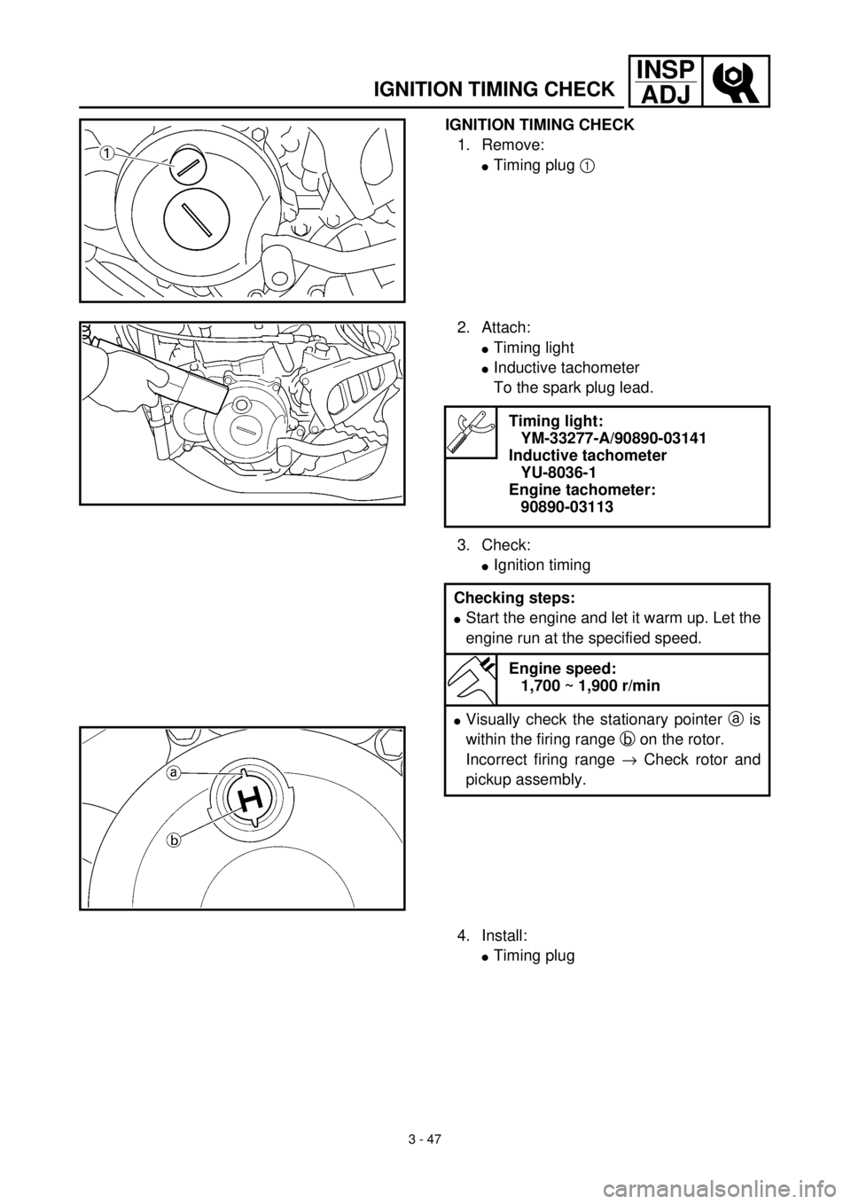
IGNITION TIMING CHECK
1. Remove:
lTiming plug 1
2. Attach:
lTiming light
lInductive tachometer
To the spark plug lead.
3. Check:
lIgnition timing
Timing light:
YM-33277-A/90890-03141
Inductive tachometer
YU-8036-1
Engine tachometer:
90890-03113
Checking steps:
lStart the engine and let it warm up. Let the
engine run at the specified speed.
Engine speed:
1,700 ~ 1,900 r/min
lVisually check the stationary pointer a is
within the firing range b on the rotor.
Incorrect firing range ® Check rotor and
pickup assembly.
4. Install:
lTiming plug
Page 574 of 654

6 - 1
–+ELEC
ELECTRICAL COMPONENTS AND WIRING DIAGRAM
EC600000
ELECTRICAL
EC610000
ELECTRICAL COMPONENTS AND WIRING DIAGRAM
EC611000
ELECTRICAL COMPONENTS
1
Headlight
2
“ENGINE STOP” button
3
Regulator
4
TPS (throttle position sensor)
5
Tail light
6
CDI magneto
7
Neutral switch
8
Ignition coil
9
Spark plug
0
Lights switch
A
CDI unit
COLOR CODE
B...................... Black
Br .................... Brown
G ..................... Green
Gy ................... Gray
L ...................... Blue
O ..................... Orange
P...................... Pink
R ..................... Red
EC612000
WIRING DIAGRAM
Sb .................... Sky blue
W ..................... White
Y ...................... Yellow
B/L ................... Black/Blue
B/W .................. Black/White
L/W .................. Blue/White
R/W .................. Red/White
6
B/L
R/WL/W
LY
L
Y
B
1B L
L YBLB YL BY
BYYLB
5LB
BYBL
LB
3
7
4 8
9
W
R Br
G P
BP
B Br
G W
R
O
L B
Y Sb
B/LSb
B/L B
Y O
L
A
2
Y
Br
B/WBB/WB
PGR
WB
L YL Y
B B/L
SbSbW
Sb
WL/W
R/WL/W
R/WSb
W2
N
13
4
5
O
B
0
6
B/WGyB/WGy