weight YAMAHA WR 400F 2000 Owners Manual
[x] Cancel search | Manufacturer: YAMAHA, Model Year: 2000, Model line: WR 400F, Model: YAMAHA WR 400F 2000Pages: 654, PDF Size: 60.12 MB
Page 10 of 654
EC050000
TO THE NEW OWNER
This manual will provide you with a good basic
understanding of features, operation, and
basic maintenance and inspection items of this
machine. Please read this manual carefully
and completely before operating your new
machine. If you have any questions regarding
the operation or maintenance of your machine,
please consult your Yamaha dealer.
NOTE:
This manual should be considered a perma-
nent part of this machine and should remain
with it even if the machine is subsequently
sold.
EC060000
NOTICE
Some data in this manual may become out-
dated due to improvements made to this
model in the future. If there is any question
you have regarding this manual or your
machine, please consult your Yamaha
dealer.
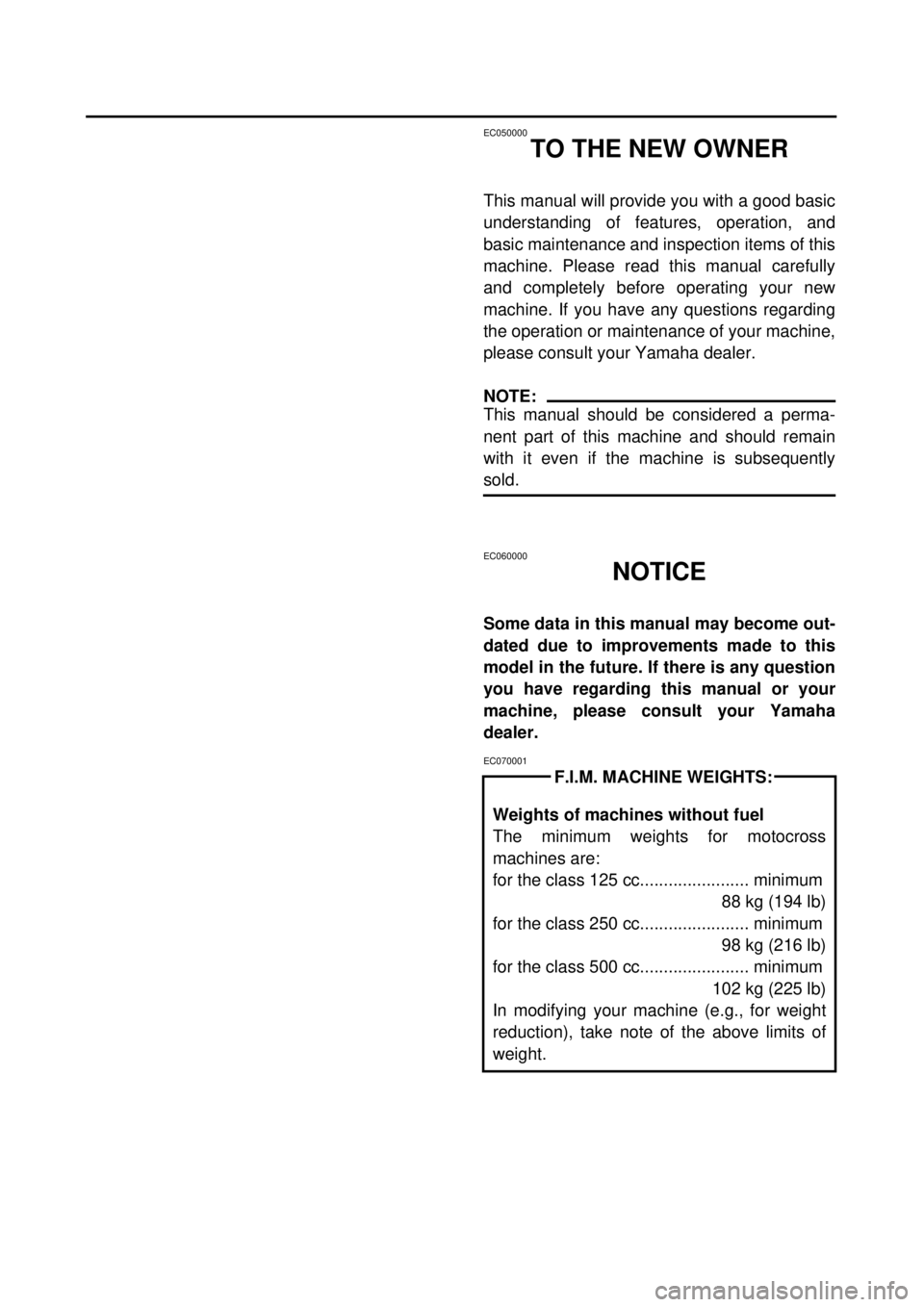
EC070001
Weights of machines without fuel
The minimum weights for motocross
machines are:
for the class 125 cc....................... minimum
88 kg (194 lb)
for the class 250 cc....................... minimum
98 kg (216 lb)
for the class 500 cc....................... minimum
102 kg (225 lb)
In modifying your machine (e.g., for weight
reduction), take note of the above limits of
weight.
F.I.M. MACHINE WEIGHTS:
Page 16 of 654
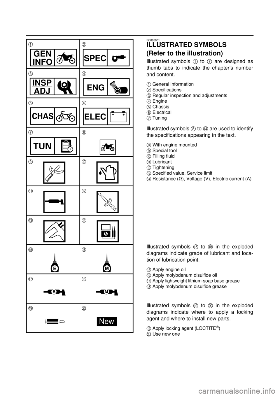
EC085001
ILLUSTRATED SYMBOLS
(Refer to the illustration)
Illustrated symbols
1
to
7
are designed as
thumb tabs to indicate the chapter’s number
and content.
1
General information
2
Specifications
3
Regular inspection and adjustments
4
Engine
5
Chassis
6
Electrical
7
Tuning
Illustrated symbols
8
to
D
are used to identify
the specifications appearing in the text.
8
With engine mounted
9
Special tool
0
Filling fluid
A
Lubricant
B
Tightening
C
Specified value, Service limit
D
Resistance (
W
), Voltage (V), Electric current (A)
Illustrated symbols
E
to
H
in the exploded
diagrams indicate grade of lubricant and loca-
tion of lubrication point.
E
Apply engine oil
F
Apply molybdenum disulfide oil
G
Apply lightweight lithium-soap base grease
H
Apply molybdenum disulfide grease
Illustrated symbols
I
to
J in the exploded
diagrams indicate where to apply a locking
agent and where to install new parts.
IApply locking agent (LOCTITE®)
JUse new one 12
34
56
78
90
AB
CD
EF
GH
IJ
GEN
INFOSPEC
INSP
ADJ
ENG
CHAS–+ELEC
TUN
T R..
ME
BM
New
Page 32 of 654
1 - 4
GEN
INFO
IMPORTANT INFORMATION
EC133000
GASKETS, OIL SEALS AND O-RINGS
1. All gaskets, oil seals, and O-rings should
be replaced when an engine is over-
hauled. All gasket surfaces, oil seal lips,
and O-rings must be cleaned.
2. Properly oil all mating parts and bearings
during reassembly. Apply grease to the
oil seal lips.
EC134000
LOCK WASHERS/PLATES AND COTTER
PINS
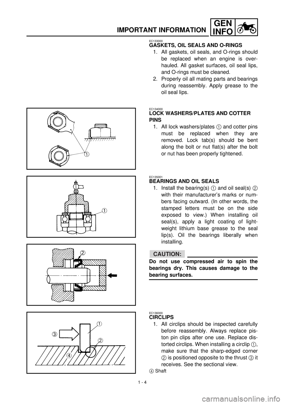
1. All lock washers/plates
1
and cotter pins
must be replaced when they are
removed. Lock tab(s) should be bent
along the bolt or nut flat(s) after the bolt
or nut has been properly tightened.
EC135001
BEARINGS AND OIL SEALS
1. Install the bearing(s)
1
and oil seal(s)
2
with their manufacturer’s marks or num-
bers facing outward. (In other words, the
stamped letters must be on the side
exposed to view.) When installing oil
seal(s), apply a light coating of light-
weight lithium base grease to the seal
lip(s). Oil the bearings liberally when
installing.
CAUTION:
Do not use compressed air to spin the
bearings dry. This causes damage to the
bearing surfaces.
EC136000
CIRCLIPS
1. All circlips should be inspected carefully
before reassembly. Always replace pis-
ton pin clips after one use. Replace dis-
torted circlips. When installing a circlip
1,
make sure that the sharp-edged corner
2 is positioned opposite to the thrust 3 it
receives. See the sectional view.
4Shaft
Page 72 of 654
2 - 1
SPEC
GENERAL SPECIFICATIONS
EC200000
SPECIFICATIONS
EC211000
GENERAL SPECIFICATIONS
Model name: WR400F (EUROPE)
WR400FM (USA)
WR400F(M) (CDN, AUS, NZ, ZA)
Model code number: 5GS5 (USA)
5GS6 (EUROPE)
5GS8 (CDN, AUS, NZ, ZA)
Dimensions:
Overall length 2,171 mm (85.5 in)
Overall width 827 mm (32.6 in)
Overall height 1,303 mm (51.3 in)
Seat height 998 mm (39.3 in)
Wheelbase 1,490 mm (58.7 in)
Minimum ground clearance 373 mm (14.7 in)
Basic weight:
With oil and full fuel tank 122.0 kg (270 lb)
Engine:
Engine type Liquid cooled 4-stroke, DOHC
Cylinder arrangement Single cylinder, forward inclined
Displacement 399 cm
3
(14.1 Imp oz, 13.5 US oz)
Bore
´
stroke 92.0
´
60.1 mm (3.62
´
2.37 in)
Compression ratio 12.5 : 1
Starting system Kick starter
Lubrication system: Dry sump
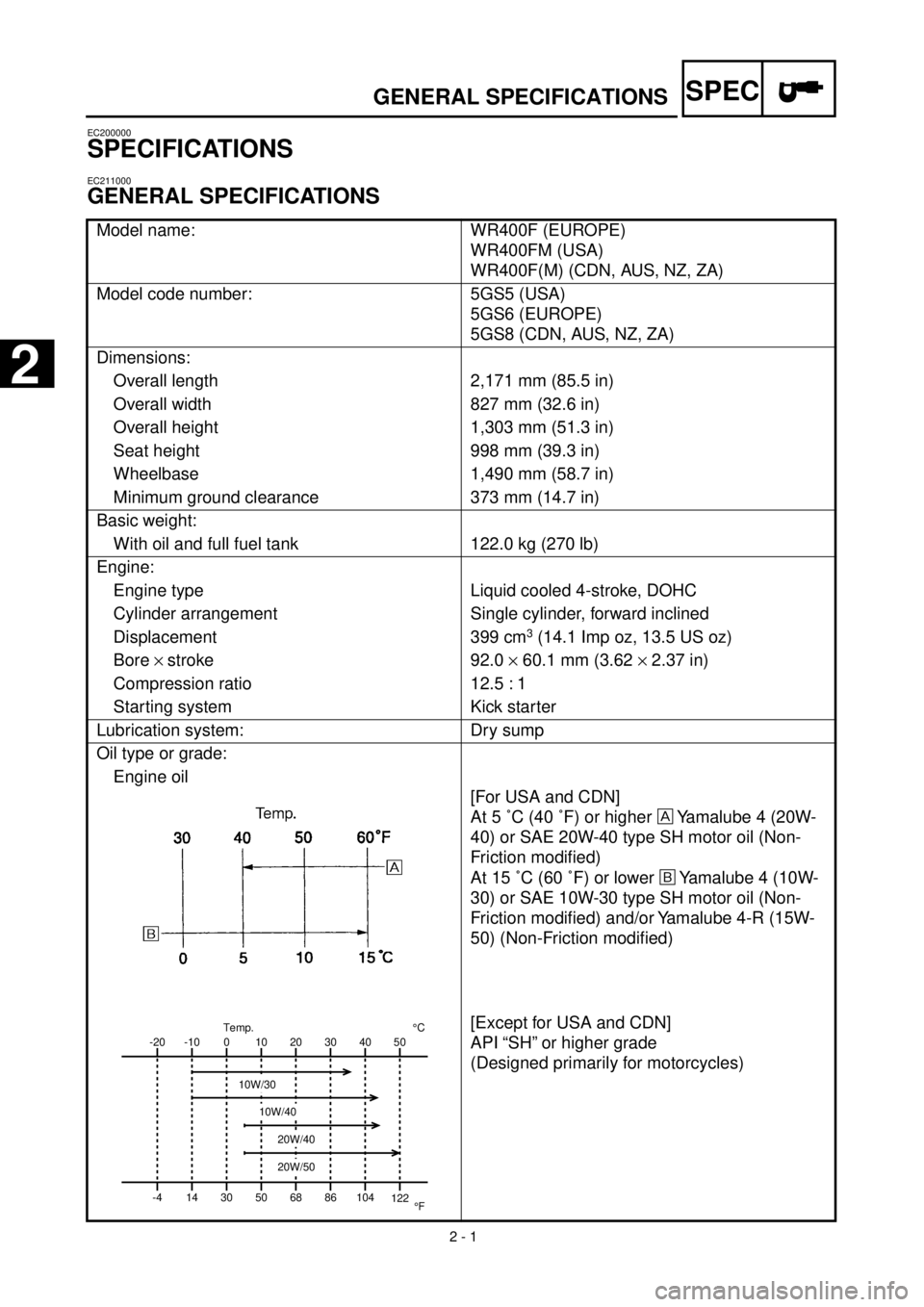
Oil type or grade:
Engine oil
[For USA and CDN]
At 5 ˚C (40 ˚F) or higher
Yamalube 4 (20W-
40) or SAE 20W-40 type SH motor oil (Non-
Friction modified)
At 15 ˚C (60 ˚F) or lower
õ
Yamalube 4 (10W-
30) or SAE 10W-30 type SH motor oil (Non-
Friction modified) and/or Yamalube 4-R (15W-
50) (Non-Friction modified)
[Except for USA and CDN]
API “SH” or higher grade
(Designed primarily for motorcycles)
-20
-4-10
140
3010
5020
6830
8640 50
104
122¡CTemp.
¡F
10W/30
10W/40
20W/40
20W/50
2
Page 83 of 654

2 - 12
SPECMAINTENANCE SPECIFICATIONS
Oil drain bolt (frame) M8 ´ 1.25 1 23 2.3 17
Oil strainer (frame) M18 ´ 1.5 1 90 9.0 65
Crankcase bearing stopper M6 ´ 1.0 15 10 1.0 7.2
Drive axle oil seal stopper M6 ´ 1.0 2 10 1.0 7.2
Ratchet wheel guide M6 ´ 1.0 2 12 1.2 8.7
Kick crank M8 ´ 1.25 1 33 3.3 24
Primary drive gear M20 ´ 1.0 1 75 7.5 54
Clutch boss M20 ´ 1.0 1 75 7.5 54
Clutch spring M6 ´ 1.0 5 8 0.8 5.8
Balancer driven gear M14 ´ 1.0 1 50 5.0 36
Balancer weight plate M6 ´ 1.0 3 10 1.0 7.2
Drive sprocket M20 ´ 1.0 1 75 7.5 54
Shift guide M6 ´ 1.0 2 10 1.0 7.2
Stopper lever M6 ´ 1.0 1 10 1.0 7.2
Segment M8 ´ 1.25 1 30 3.0 22
Neutral switch M5 ´ 0.8 2 4 0.4 2.9 Part to be tightened Thread size Q’tyTightening torque
Nm m·kg ft·lb
Page 89 of 654
2 - 18
SPEC
GENERAL TORQUE SPECIFICATIONS/
DEFINITION OF UNITS
EC220001
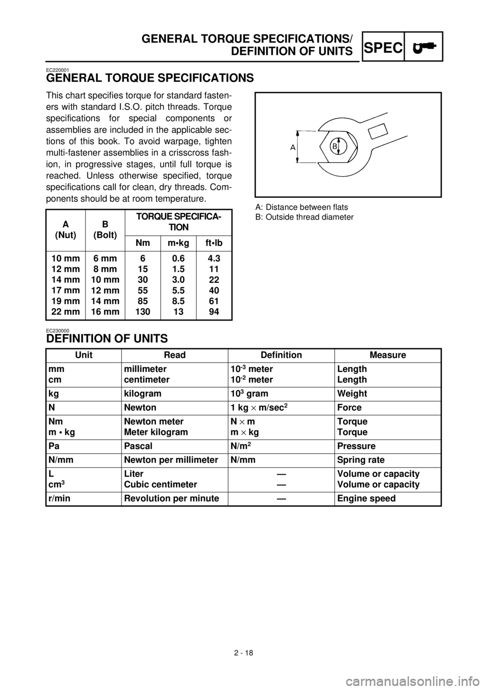
GENERAL TORQUE SPECIFICATIONS
This chart specifies torque for standard fasten-
ers with standard I.S.O. pitch threads. Torque
specifications for special components or
assemblies are included in the applicable sec-
tions of this book. To avoid warpage, tighten
multi-fastener assemblies in a crisscross fash-
ion, in progressive stages, until full torque is
reached. Unless otherwise specified, torque
specifications call for clean, dry threads. Com-
ponents should be at room temperature.
A
(Nut)B
(Bolt)TORQUE SPECIFICA-
TION
Nm m•kg ft•lb
10 mm
12 mm
14 mm
17 mm
19 mm
22 mm6 mm
8 mm
10 mm
12 mm
14 mm
16 mm6
15
30
55
85
1300.6
1.5
3.0
5.5
8.5
134.3
11
22
40
61
94
A: Distance between flats
B: Outside thread diameter
EC230000
DEFINITION OF UNITS
Unit Read Definition Measure
mm
cmmillimeter
centimeter10
-3
meter
10
-2
meterLength
Length
kg kilogram 10
3
gram Weight
N Newton 1 kg
´
m/sec
2
Force
Nm
m • kgNewton meter
Meter kilogramN
´
m
m
´
kgTorque
Torque
Pa Pascal N/m
2
Pressure
N/mm Newton per millimeter N/mm Spring rate
L
cm
3
Liter
Cubic centimeter—
—Volume or capacity
Volume or capacity
r/min Revolution per minute — Engine speed
Page 254 of 654
3 - 45
INSP
ADJ
LUBRICATION
EC36a041
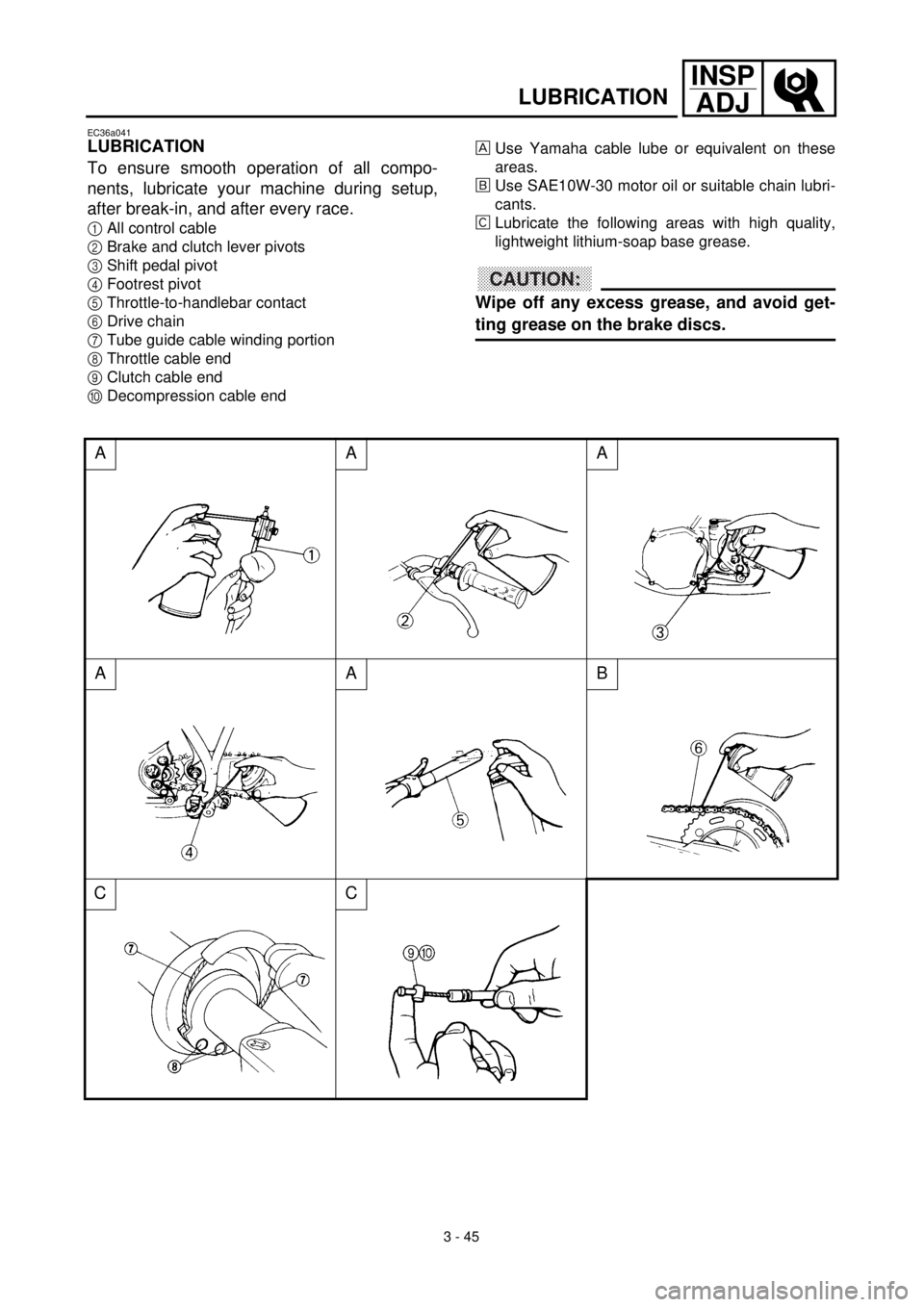
LUBRICATION
To ensure smooth operation of all compo-
nents, lubricate your machine during setup,
after break-in, and after every race.
1All control cable
2Brake and clutch lever pivots
3Shift pedal pivot
4Footrest pivot
5Throttle-to-handlebar contact
6Drive chain
7Tube guide cable winding portion
8Throttle cable end
9Clutch cable end
0Decompression cable end
AAA
AAB
CC
Use Yamaha cable lube or equivalent on these
areas.
õUse SAE10W-30 motor oil or suitable chain lubri-
cants.
‚Lubricate the following areas with high quality,
lightweight lithium-soap base grease.
CAUTION:
Wipe off any excess grease, and avoid get-
ting grease on the brake discs.
Page 286 of 654
4 - 12
ENGCARBURETOR
EC464511
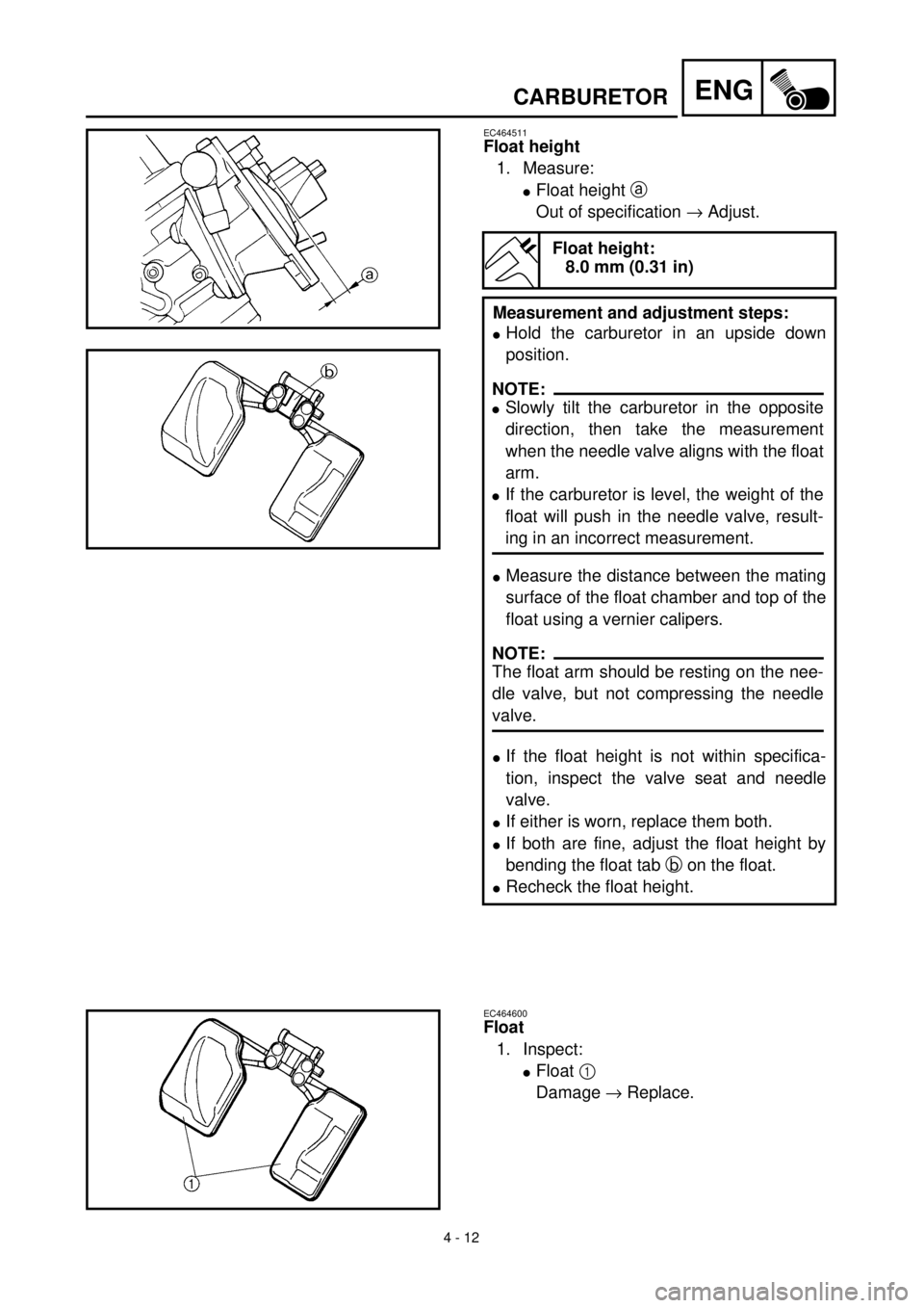
Float height
1. Measure:
lFloat height a
Out of specification ® Adjust.
Float height:
8.0 mm (0.31 in)
Measurement and adjustment steps:
lHold the carburetor in an upside down
position.
lMeasure the distance between the mating
surface of the float chamber and top of the
float using a vernier calipers.
lIf the float height is not within specifica-
tion, inspect the valve seat and needle
valve.
lIf either is worn, replace them both.
lIf both are fine, adjust the float height by
bending the float tab b on the float.
lRecheck the float height.
NOTE:
lSlowly tilt the carburetor in the opposite
direction, then take the measurement
when the needle valve aligns with the float
arm.
lIf the carburetor is level, the weight of the
float will push in the needle valve, result-
ing in an incorrect measurement.
NOTE:
The float arm should be resting on the nee-
dle valve, but not compressing the needle
valve.
EC464600
Float
1. Inspect:
lFloat 1
Damage ® Replace.
Page 376 of 654
4 - 57
ENGBALANCER
REMOVAL POINTS
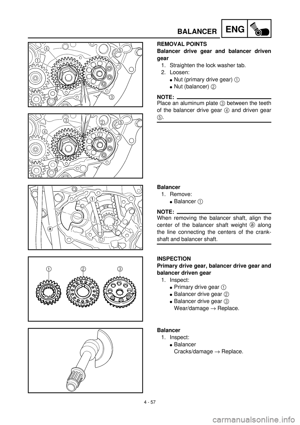
Balancer drive gear and balancer driven
gear
1. Straighten the lock washer tab.
2. Loosen:
lNut (primary drive gear) 1
lNut (balancer) 2
NOTE:
Place an aluminum plate 3 between the teeth
of the balancer drive gear 4 and driven gear
5.
Balancer
1. Remove:
lBalancer 1
NOTE:
When removing the balancer shaft, align the
center of the balancer shaft weight a along
the line connecting the centers of the crank-
shaft and balancer shaft.
INSPECTION
Primary drive gear, balancer drive gear and
balancer driven gear
1. Inspect:
lPrimary drive gear 1
lBalancer drive gear 2
lBalancer drive gear 3
Wear/damage ® Replace.
Balancer
1. Inspect:
lBalancer
Cracks/damage ® Replace.
Page 378 of 654
4 - 58
ENGBALANCER
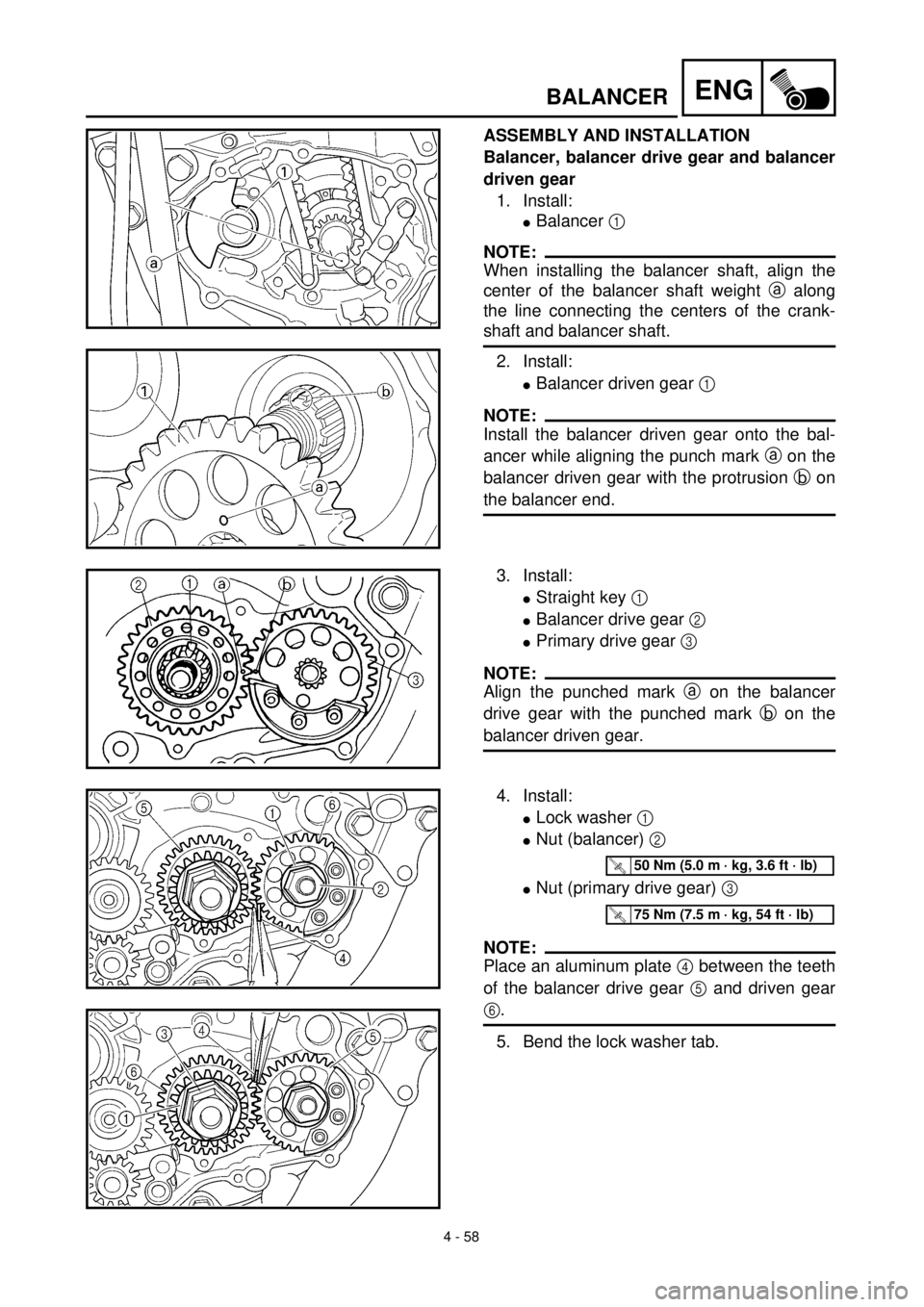
ASSEMBLY AND INSTALLATION
Balancer, balancer drive gear and balancer
driven gear
1. Install:
lBalancer 1
NOTE:
When installing the balancer shaft, align the
center of the balancer shaft weight a along
the line connecting the centers of the crank-
shaft and balancer shaft.
2. Install:
lBalancer driven gear 1
NOTE:
Install the balancer driven gear onto the bal-
ancer while aligning the punch mark a on the
balancer driven gear with the protrusion b on
the balancer end.
3. Install:
lStraight key 1
lBalancer drive gear 2
lPrimary drive gear 3
NOTE:
Align the punched mark a on the balancer
drive gear with the punched mark b on the
balancer driven gear.
4. Install:
lLock washer 1
lNut (balancer) 2
lNut (primary drive gear) 3
NOTE:
Place an aluminum plate 4 between the teeth
of the balancer drive gear 5 and driven gear
6.
5. Bend the lock washer tab.
T R..50 Nm (5.0 m · kg, 3.6 ft · lb)
T R..75 Nm (7.5 m · kg, 54 ft · lb)