engine YAMAHA WR 426F 2001 Owners Manual
[x] Cancel search | Manufacturer: YAMAHA, Model Year: 2001, Model line: WR 426F, Model: YAMAHA WR 426F 2001Pages: 762, PDF Size: 62.36 MB
Page 687 of 762
–+ELECSISTEMA DE ENCENDIDO
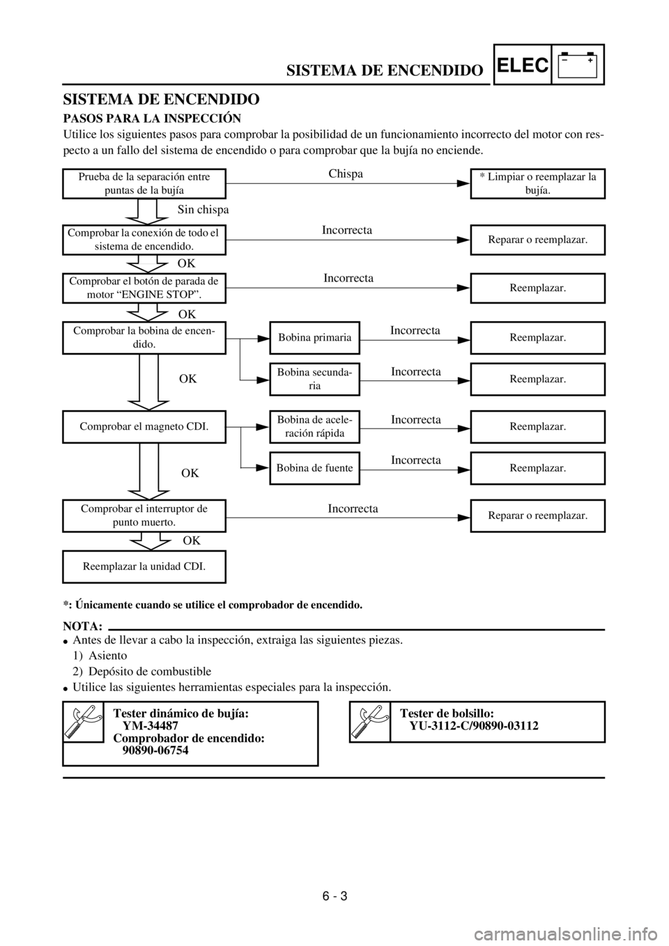
SISTEMA DE ENCENDIDO
PASOS PARA LA INSPECCIÓN
Utilice los siguientes pasos para comprobar la posibilidad de un funcionamiento incorrecto del motor con res-
pecto a un fallo del sistema de encendido o para comprobar que la bujía no enciende.
*: Únicamente cuando se utilice el comprobador de encendido.
NOTA:
lAntes de llevar a cabo la inspección, extraiga las siguientes piezas.
1) Asiento
2) Depósito de combustible
lUtilice las siguientes herramientas especiales para la inspección.
Prueba de la separación entre
puntas de la bujía* Limpiar o reemplazar la
bujía.
Comprobar la conexión de todo el
sistema de encendido.Reparar o reemplazar.
Comprobar el botón de parada de
motor “ENGINE STOP”.Reemplazar.
Comprobar la bobina de encen-
dido.Bobina primaria Reemplazar.
Bobina secunda-
riaReemplazar.
Comprobar el magneto CDI.Bobina de acele-
ración rápidaReemplazar.
Bobina de fuente Reemplazar.
Comprobar el interruptor de
punto muerto.Reparar o reemplazar.
Reemplazar la unidad CDI.
Tester dinámico de bujía:
YM-34487
Comprobador de encendido:
90890-06754Tester de bolsillo:
YU-3112-C/90890-03112
Sin chispa
OK
Chispa
Incorrecta
Incorrecta
Incorrecta
Incorrecta
Incorrecta
Incorrecta
Incorrecta
OK
OK
OK
OK
6 - 3
Page 688 of 762

6 - 4
–+ELEC
IGNITION SYSTEM
EC622001
SPARK GAP TEST
1. Disconnect the spark plug cap from spark
plug.
2. Connect the dynamic spark tester
1
(ignition checker
2
) as shown.
l
Spark plug cap
3
l
Spark plug
4
For USA and CDN
õ
Except for USA and CDN
3. Kick the kick starter.
4. Check the ignition spark gap.
5. Start engine, and increase spark gap
until misfire occurs. (for USA and CDN
only)
Minimum spark gap:
6.0 mm (0.24 in)
õ
EC624000
COUPLERS AND LEADS CONNECTION
INSPECTION
1. Check:
l
Couplers and leads connection
Rust/dust/looseness/short-circuit
®
Repair or replace.
EC625001
“ENGINE STOP” BUTTON INSPECTION
1. Inspect:
l
“ENGINE STOP” button conduct
No continuity while being pushed
®
Replace.
Continuity while being freed
®
Replace.
Tester (+) lead
®
Black/White lead
1
Tester (–) lead
®
Black lead
2
B/W
1
B
2
Tester selec-
tor position
PUSH IN
W
´
1
FREE
Page 689 of 762

–+ELEC
SYSTEME D’ALLUMAGE
ZÜNDANLAGE
SISTEMA DE ENCENDIDO
ZÜNDFUNKENSTRECKE KON-
TROLLIEREN
1. Den Zündkerzenstecker von
der Zündkerze abziehen.
2. Den Zündfunkenstreckente-
ster 1 (bzw. 2) wie abgebil-
det anschließen.
lZündkerzenstecker 3
lZündkerze 4
Nur USA und CDN
õNicht USA und CDN
3.Den Motor mit dem Kick-
starter durchdrehen
.
4. Die Zündfunkenstrecke kon-
trollieren.
5. Den Motor anlassen und die
Zündfunkenstrecke vergrö-
ßern, bis es zu Fehlzündun-
gen kommt (nur USA und
CDN).
Min. Zündfunkenstrecke
6,0 mm
STECKVERBINDER- UND KABEL-
ANSCHLÜSSE KONTROLLIEREN
1. Kontrollieren:
lSteckverbinder- und Kabel-
anschlüsse
Rost/Staub/Lockerheit/Kurz-
schluß ® Instand setzen
oder erneuern.
MOTORSTOPPSCHALTER “ENGI-
NE STOP” KONTROLLIEREN
1. Kontrollieren:
lMotorstoppschalter
(auf Durchgang)
Kein Durchgang bei gedrücktem
Schalter ® Erneuern.
Durchgang bei freigelassenem
Schalter ® Erneuern. Meßkabel (+) ®
Schwarz/Weiß Kabel 1
Meßkabel (–) ®
Schwarz Kabel 2
B/W
1 B
2 Meßge-
rät-
Einstel-
GE-
DRÜCKT
W ´ 1
FREI
TEST DE L’INTERVALLE D’ETIN-
CELLEMENT D’ALLUMAGE
1. Déconnecter le capuchon de bou-
gie de la bougie.
2. Connecter le testeur dynamique
d’étincelle 1 (testeur d’allu-
mage 2) comme indiqué.
lCapuchon de bougie 3
lBougie 4
Pour les USA et le CDN
õExcepté pour les USA et le CDN
3. Actionner le démarreur au pied.
4. Contrôler la longueur d’étincelle
d’allumage.
5. Démarrer le moteur et augmenter
la longueur d’étincelle jusqu’à ce
qu’un raté se produise. (unique-
ment USA et CDN)
Longueur d’étincelle mini-
mum:
6,0 mm (0,24 in)
CONTROLE DES CONNEXIONS
DE COUPLEURS ET FILS
1. Contrôler:
lConnexion de coupleurs et fils
Rouille/poussière/jeu/court-cir-
cuit ® Réparer ou changer.
CONTROLE DU BOUTON
D’ARRET DU MOTEUR “ENGINE
STOP”
1. Vérifier:
lContinuité du bouton d’arrêt du
moteur “ENGINE STOP”
Pas de continuité lorsque enfoncé ®
Changer.
Continuité lorsque relâché ® Changer. Fil (+) de multimètre ®
Fil noir/blanc 1
Fil (–) de multimètre ® Fil noir 2
B/W
1B
2Position de
sélecteur
du multi-
mètre
EN-
FONCE
W ´ 1
RE-
LACHE
6 - 4
PRUEBA DE LA SEPARACIÓN
ENTRE PUNTAS DE LA BUJÍA
1. Desconecte la tapa de puntas de la
bujía de la bujía misma.
2. Conecte el tester dinámico de la
bujía 1 (comprobador de encen-
dido 2) tal y como se muestra.
lTapa de la bujía 3
lBujía 4
Para USA y CDN
õExcepto USA y CDN
3. Accione el arrancador del pedal.
4. Compruebe la separación entre
puntas de la bujía de encendido.
5. Arranque el motor e incremente
la separación entre puntas de la
bujía hasta que deje de saltar la
chispa (solamente para USA y
CDN).
Separación entre puntas
mínima de la bujía:
6,0 mm (0,24 in)
INSPECCIÓN DE ACOPLADORES
Y CONEXIÓN DE CABLES
1. Comprobar:
lConexión de acopladores y
cables
Oxido/polvo/flojedad/cortocir-
cuito ® Reparar o reemplazar.
INSPECCIÓN DEL BOTÓN DE
PARADA DE MOTOR “ENGINE
STOP”
1. Inspeccionar:
lConducto del botón de parada
de motor “ENGINE STOP”
Sin continuidad mientras se mantiene
pulsado ® Reemplazar.
Con continuidad mientras se suelta ®
Reemplazar.Cable del tester (+) ®
Cable negro/blanco 1
Cable del tester (–) ®
Cable negro 2
B/W
1B
2Posición
del selec-
tor del tes-
ter
PULSAR
(PUSH
IN)
W ´ 1
LIBRE
Page 694 of 762

6 - 7
–+ELECTPS (THROTTLE POSITION SENSOR) SYSTEM
EC69000
TPS (THROTTLE POSITION SENSOR) SYSTEM
INSPECTION STEPS
If the TPS will not operate, use the following inspection steps.
*marked: Refer to “IGNITION SYSTEM” section.
NOTE:
lRemove the following parts before inspection.
1) Seat
2) Fuel tank
lUse the following special tools in this inspection.
Check entire ignition
system for connection.Repair or replace.
Check TPS. TPS coil Replace.
*Check CDI magneto. Source coil Replace.
Check CDI unit.TPS input
voltageReplace.
Pocket tester:
YU-3112-C/90890-03112Inductive tachometer:
YU-08036-B
Engine tachometer:
90890-03113
No good
No good
No good
No good
OK
OK
OK
Page 702 of 762

6 - 10
–+ELECTPS (THROTTLE POSITION SENSOR) SYSTEM
6. Adjust:
lTPS coil resistance at idle speed
Adjustment steps:
Adjust the angle of the TPS 1 to obtain
the resistance calculated (example: 650 ~
750 W)
Tester (+) lead ® Yellow lead 2
Tester (–) lead ® Black lead 3
7. Tighten:
lScrew (TPS) 1
8. Install:
lTPS coupler
EC694000
TPS INPUT VOLTAGE INSPECTION
1. Disconnect the TPS coupler.
2. Start the engine.
3. Inspect:
lTPS input voltage
Out of specification ® Replace the CDI
unit.
Tester (+) lead ® Blue lead 1
Tester (–) lead ® Black/Blue lead 2
TPS input
voltageTester selector
position
4 ~ 6 V DCV-20
Page 710 of 762
7 - 1
TUN
EC700000
TUNING
EC710000
ENGINE
Carburetor setting
l
The air/fuel mixture will vary depending on
atmospheric conditions. Therefore, it is nec-
essary to take into consideration the air pres-
sure, ambient temperature, humidity, etc.,
when adjusting the carburetor.
l
Perform a test run to check for proper engine
performance (e.g., throttle response) and
spark plug(-s) discoloration or fouling. Use
these readings to determine the best possi-
ble carburetor setting.
NOTE:
It is recommended to keep a record of all car-
buretor settings and external conditions (e.g.,
atmospheric conditions, track/surface condi-
tions, lap times) to make future carburetor set-
ting easier.
WARNING
l
The carburetor is a part of the fuel line.
Therefore, be sure to install it in a well-
ventilated area, away from flammable
objects and any sources of fire.
l
Never look into the carburetor intake.
Flames may shoot out from the pipe if the
engine backfires while it is being started.
Gasoline may be discharged from the
accelerator pump nozzle when the carbu-
retor has been removed.
SETTING
7
7
Page 712 of 762

7 - 2
TUN
CAUTION:
l
The carburetor is extremely sensitive to
foreign matter (dirt, sand, water, etc.).
During installation, do not allow foreign
matter to get into the carburetor.
l
Always handle the carburetor and its
components carefully. Even slight
scratches, bends or damage to carbure-
tor parts may prevent the carburetor from
functioning correctly. Carefully perform
all servicing with the appropriate tools
and without applying excessive force.
l
When the engine is stopped or when
riding at no load, do not open and close
the throttle unnecessarily. Otherwise, too
much fuel may be discharged, starting
may become difficult or the engine may
not run well.
l
After installing the carburetor, check that
the throttle operates correctly and opens
and closes smoothly.
Atmospheric conditions and carburetor
settings
The air density (i.e., concentration of oxygen
in the air) determines the richness or lean-
ness of the air/fuel mixture. Therefore, refer
to the above table for mixture settings.
That is:
l
Higher temperature expands the air with its
resultant reduced density.
l
Higher humidity reduces the amount of oxy-
gen in the air by so much of the water vapor
in the same air.
l
Lower atmospheric pressure (at a high alti-
tude) reduces the density of the air.
Air temp. HumidityAir
pressure
(altitude)Mixture Setting
High High Low (high) Richer Leaner
Low Low High (low) Leaner Richer
SETTING
Page 716 of 762
7 - 4
TUN
SETTING
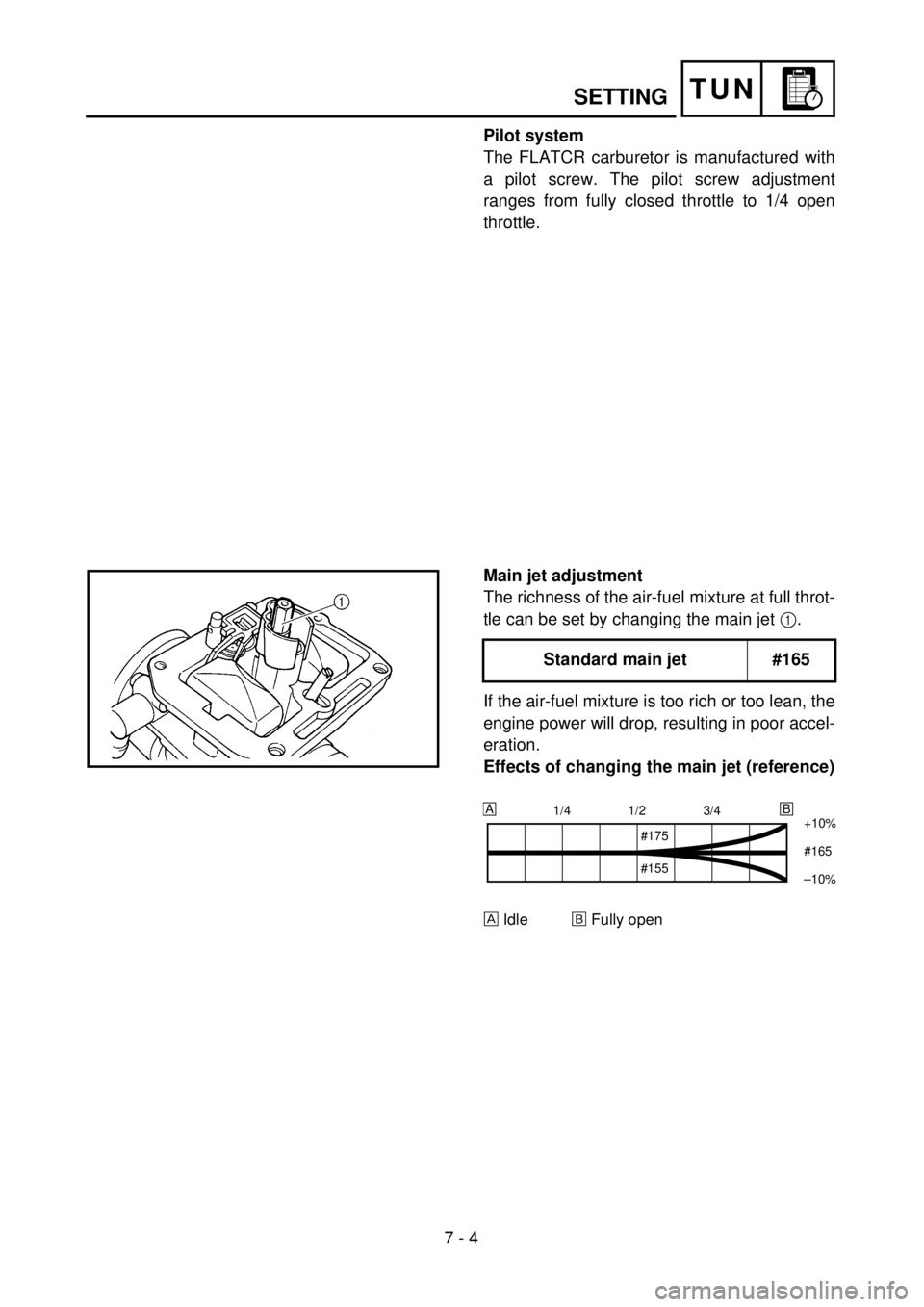
Pilot system
The FLATCR carburetor is manufactured with
a pilot screw. The pilot screw adjustment
ranges from fully closed throttle to 1/4 open
throttle.
Main jet adjustment
The richness of the air-fuel mixture at full throt-
tle can be set by changing the main jet
1
.
If the air-fuel mixture is too rich or too lean, the
engine power will drop, resulting in poor accel-
eration.
Effects of changing the main jet (reference)
Idle
õ
Fully open
Standard main jet #165
1/4 1/2 3/4
+10%
#165
–10
%
AB
#175
#155
Page 720 of 762
7 - 6
TUN
SETTING
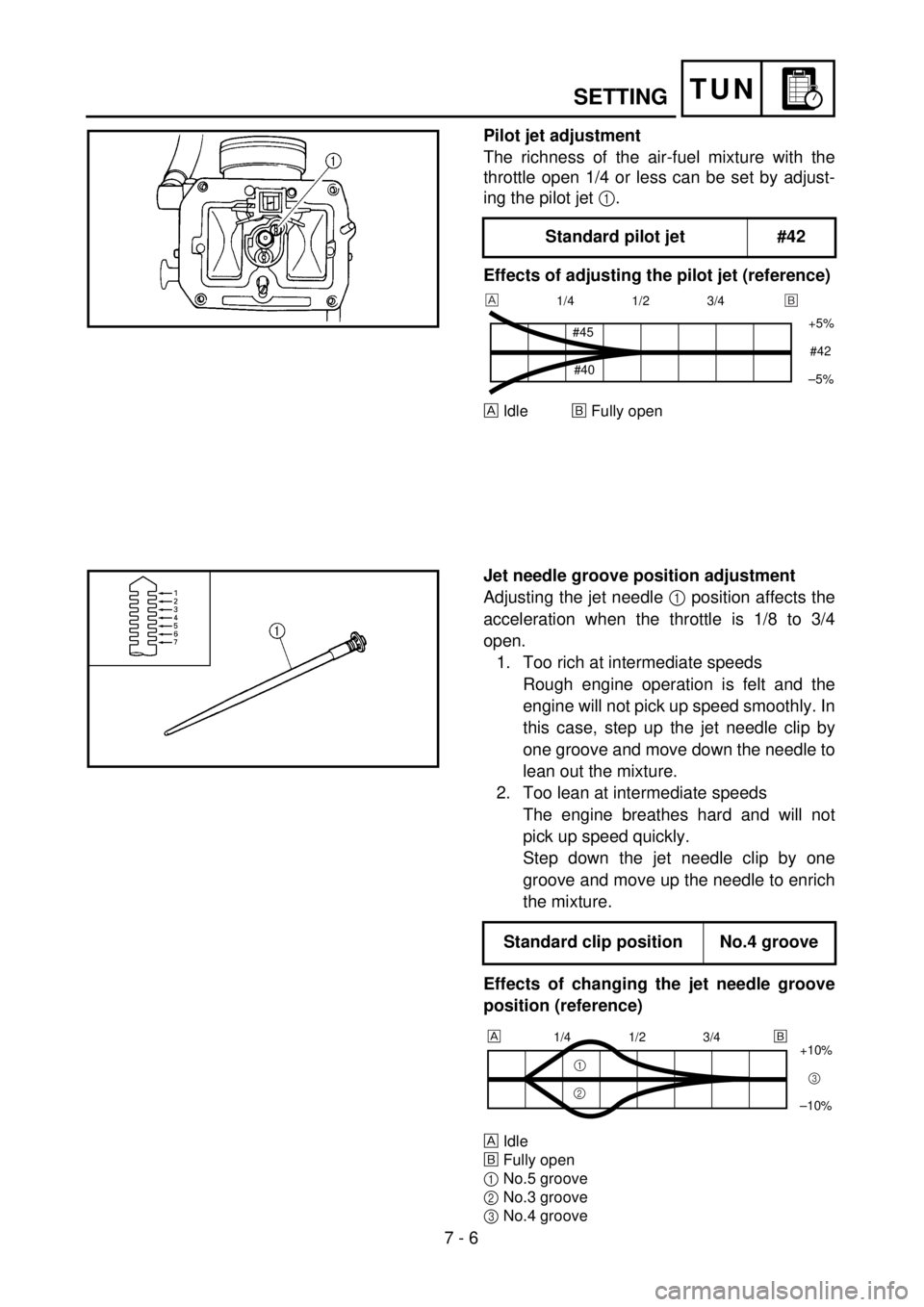
Pilot jet adjustment
The richness of the air-fuel mixture with the
throttle open 1/4 or less can be set by adjust-
ing the pilot jet
1
.
Effects of adjusting the pilot jet (reference)
Idle
õ
Fully open
Standard pilot jet #42
1/4 1/2 3/4
+5%
–5%
#45
#40#42
õ
Jet needle groove position adjustment
Adjusting the jet needle
1 position affects the
acceleration when the throttle is 1/8 to 3/4
open.
1. Too rich at intermediate speeds
Rough engine operation is felt and the
engine will not pick up speed smoothly. In
this case, step up the jet needle clip by
one groove and move down the needle to
lean out the mixture.
2. Too lean at intermediate speeds
The engine breathes hard and will not
pick up speed quickly.
Step down the jet needle clip by one
groove and move up the needle to enrich
the mixture.
Effects of changing the jet needle groove
position (reference)
Idle
õFully open
1No.5 groove
2No.3 groove
3No.4 groove
Standard clip position No.4 groove
1/4 1/2 3/4
+10%
–10%
1
23
õ
Page 728 of 762
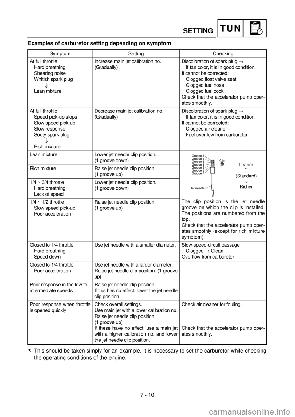
7 - 10
TUNSETTING
Examples of carburetor setting depending on symptom
This should be taken simply for an example. It is necessary to set the carburetor while checking
the operating conditions of the engine.
Symptom Setting Checking
At full throttle
Hard breathing
Shearing noise
Whitish spark plug
Lean mixtureIncrease main jet calibration no.
(Gradually)Discoloration of spark plug ®
If tan color, it is in good condition.
If cannot be corrected:
Clogged float valve seat
Clogged fuel hose
Clogged fuel cock
Check that the accelerator pump oper-
ates smoothly.
At full throttle
Speed pick-up stops
Slow speed pick-up
Slow response
Sooty spark plug
Rich mixtureDecrease main jet calibration no.
(Gradually)Discoloration of spark plug ®
If tan color, it is in good condition.
If cannot be corrected:
Clogged air cleaner
Fuel overflow from carburetor
Lean mixture Lower jet needle clip position.
(1 groove down)
The clip position is the jet needle
groove on which the clip is installed.
The positions are numbered from the
top.
Check that the accelerator pump oper-
ates smoothly (except for rich mixture
symptom). Rich mixture Raise jet needle clip position.
(1 groove up)
1/4 ~ 3/4 throttle
Hard breathing
Lack of speedLower jet needle clip position.
(1 groove down)
1/4 ~ 1/2 throttle
Slow speed pick-up
Poor accelerationRaise jet needle clip position.
(1 groove up)
Closed to 1/4 throttle
Hard breathing
Speed downUse jet needle with a smaller diameter. Slow-speed-circuit passage
Clogged ® Clean.
Overflow from carburetor
Closed to 1/4 throttle
Poor accelerationUse jet needle with a larger diameter.
Raise jet needle clip position. (1 groove
up)
Poor response in the low to
intermediate speedsRaise jet needle clip position.
If this has no effect, lower the jet needle
clip position.
Poor response when throttle
is opened quicklyCheck overall settings.
Use main jet with a lower calibration no.
Raise jet needle clip position.
(1 groove up)
If these have no effect, use a main jet
with a higher calibration no. and lower
the jet needle clip position.Check air cleaner for fouling.
Check that the accelerator pump oper-
ates smoothly.
Jet needleClip
Groobe 7 Groobe 6
Groobe 5
Groobe 4
Groobe 3
Groobe 2
Groobe 1
Leaner
(Standard)
¯
Richer
*