stop start YAMAHA WR 450F 2005 User Guide
[x] Cancel search | Manufacturer: YAMAHA, Model Year: 2005, Model line: WR 450F, Model: YAMAHA WR 450F 2005Pages: 758, PDF Size: 17.3 MB
Page 75 of 758

GEN
INFO
8. Alle lackierten und verchromten
Oberflächen mit Pflegewachs
behandeln. Keine Pflegemittel
mit Scheurmitteln verwenden,
um Kratzer zu vermeiden.
9. Anschließend den Motor anlas-
sen und einige Minuten lang
betreiben.
LAGERUNG
Soll das Motorrad länger als 60 Tage
gelagert werden, sind gewisse
Schutzmaßnahmen notwendig. Das
Motorrad nach der Wäsche, wie
nachfolgend beschrieben, auf die
Lagerung vorbereiten:
1. Das Benzin aus dem Kraftstoff-
tank ablassen und den Verga-
ser entleeren.
2. Die Zündkerze herausdrehen,
einen Eßlöffel SAE 10W-30-
Motoröl in die Zündkerzenboh-
rung gießen und die Zündkerze
wieder eindrehen. Bei betätig-
tem Motorstoppschalter mehr-
mals den Kickstarterhebel
durchtreten, um die Zylinder-
wandungen mit Öl zu bedecken.
3. Die Antriebskette abnehmen,
gründlich reinigen und anschlie-
ßend schmieren. Die Kette mon-
tieren oder in einem am Rahmen
angebundenen Plastikbeutel
aufbewahren.
4. Sämtliche Seilzüge ölen.
5. Das Motorrad so abstützen, daß
die Räder sich frei drehen las-
sen.
6. Einen Plastikbeutel über die
Schalldämpferöffnung binden,
damit keine Feuchtigkeit ein-
dringt.
7. Ist der Lagerort feucht oder salz-
haltig, sämtliche Metallflächen
mit Sprühöl behandeln. Öl von
Gummiteilen und der Sitzbank
fernhalten.
HINWEIS:
Anfallende Reparaturen oder Inspek-
tion vor der Stillegung ausführen 8. Une cire pour carrosserie peut être
utilisée pour toutes les surfaces
peintes et chromées. Ne pas
employer de cires détergentes car
elles contiennent souvent des abra-
sifs.
9. Lorsque le nettoyage est terminé,
mettre le moteur en marche et le
laisser tourner au ralenti pendant
plusieurs minutes.
REMISAGE
Si la moto doit être remisée pour 60
jours ou plus, il convient de prendre cer-
taines précautions pour éviter tout
endommagement. Après un nettoyage
complet de la moto, la préparer comme
suit pour le remisage:
1. Vidanger le réservoir de carburant,
le circuit de carburant et la cuve à
niveau constant du carburateur.
2. Déposer la bougie, verser une
cuillère à soupe d’huile moteur SAE
10W-30 dans le trou de bougie et
replacer la bougie. Enfoncer le
coupe-circuit du moteur et lancer
quelques fois le moteur à l’aide de
la pédale de démarrage afin de
répartir l’huile sur les parois du
cylindre.
3. Déposer la chaîne de transmission,
la nettoyer soigneusement à l’aide
d’un solvant puis la graisser.
Remettre en place la chaîne ou la
conserver dans un sachet en plasti-
que (attaché au cadre pour éviter de
l’égarer).
4. Lubrifier tous les câbles de com-
mande.
5. Placer un support sous le cadre afin
de surélever les deux roues.
6. Couvrir la sortie du tuyau d’échap-
pement d’un sachet en plastique
pour empêcher la pénétration
d’humidité.
7. Si la moto doit être remisée dans un
lieu très humide ou exposé à l’air
marin, enduire toutes les surfaces
métalliques extérieures d’une fine
couche d’huile. Ne pas enduire
d’huile les parties en caoutchouc et
la housse de selle.
N.B.:
Effectuer toutes les réparations nécessai-
res avant de remiser la moto.8. Puede aplicar cera de automóviles a
todas las superficies pintadas o cro-
madas. Evite la combinación de
limpiadores y ceras, ya que pueden
contener abrasivos.
9. Una vez terminada la operación de
limpieza, arranque el motor y déjelo
al ralentí unos minutos.
ALMACENAMIENTO
Si va a dejar la máquina guardada
durante 60 días o más, debe adoptar
algunas medidas preventivas a fin de
evitar su deterioro. Después de limpiar a
fondo la máquina, prepárela para su
almacenamiento del modo siguiente:
1. Vacíe el depósito de combustible,
los tubos de combustible y la cubeta
del flotador del carburador.
2. Extraiga la bujía, vierta una cucha-
rada sopera de aceite de motor SAE
10W-30 en el cilindro por el orificio
de la bujía y vuelva a colocar esta.
Con el interruptor de paro del motor
pulsado, accione el pedal de arran-
que varias veces para que el aceite
se reparta por las paredes del cilin-
dro.
3. Desmonte la cadena de transmisión,
límpiela a fondo con disolvente y
lubríquela. Vuelva a montar la
cadena o guárdela en una bolsa de
plástico sujeta al bastidor.
4. Lubrique todos los cables de con-
trol.
5. Eleve el bastidor y sujételo para que
las ruedas queden levantadas del
suelo.
6. Cubra la salida del tubo de escape
con una bolsa de plástico para impe-
dir que entre humedad.
7. Si la máquina debe permanecer
almacenada en un ambiente húmedo
o salado, aplique una capa fina de
aceite ligero a todas las superficies
de metal expuestas. No aplique
aceite a las piezas de goma o a la
funda del sillín.
NOTA:
Efectúe todas las reparaciones necesarias
antes de guardar la máquina.
NETTOYAGE ET REMISAGE
PFLEGE UND LAGERUNG
LIMPIEZA Y ALMACENAMIENTO
1 - 21
Page 87 of 758

SPEC
2 - 12
NOTE:
- marked portion shall be checked for torque tightening after break-in or before each race.
NOTE:
*1: Tighten the cylinder head bolts to 30 Nm (3.0 m kg, 22 ft lb) in the proper tightening sequence,
remove and retighten the cylinder head bolts to 20 Nm (2.0 m kg, 14 ft lb) in the proper tightening
sequence, and then tighten the cylinder head bolts further to reach the specified angle 180° in the
proper tightening sequence.Oil check bolt M6 × 1.0 1 10 1.0 7.2
Oil hose clamp—220.21.4
Clutch cover M6 × 1.0 7 10 1.0 7.2
Crankcase cover (right) M6 × 1.0 10 10 1.0 7.2
Crankcase cover (left) M6 × 1.0 9 10 1.0 7.2
Idle gear cover (starter motor) M6 × 1.0 2 10 1.0 7.2
Crankcase M6 × 1.0 12 12 1.2 8.7
Clutch cable holder M6 × 1.0 1 10 1.0 7.2
Oil drain bolt (crankcase rear) M10 × 1.25 1 20 2.0 14
(crankcase left) M6 × 1.0 1 10 1.0 7.2
Oil drain bolt (frame) M8 × 1.25 1 23 2.3 17
Oil strainer (frame) M14 × 1.5 1 70 7.0 50
Crankcase bearing stopper M6 × 1.0 15 10 1.0 7.2
Drive axle oil seal stopper M6 × 1.0 2 10 1.0 7.2
Ratchet wheel guide M6 × 1.0 2 12 1.2 8.7
Kickstarter M8 × 1.25 1 33 3.3 24
Screw (kickstarter) M6 × 1.0 1 7 0.7 5.1
Starter clutch M6 × 1.0 6 16 1.6 11
Primary drive gear M20 × 1.0 1 110 11.0 80
Clutch boss M20 × 1.0 1 75 7.5 54
Push lever M6 × 1.0 1 10 1.0 7.2
Clutch spring M6 × 1.0 6 8 0.8 5.8
Balancer driven gear M14 × 1.0 1 50 5.0 36
Balancer weight plate M6 × 1.0 3 10 1.0 7.2
Drive sprocket M20 × 1.0 1 75 7.5 54
Drive sprocket cover M6 × 1.0 2 8 0.8 5.8
Shift pedal M6 × 1.0 1 12 1.2 8.7
Shift guide M6 × 1.0 2 10 1.0 7.2
Stopper lever M6 × 1.0 1 10 1.0 7.2
Segment M8 × 1.25 1 30 3.0 22 Part to be tightened Thread size Q’tyTightening torque
Nm m·kg ft·lb
MAINTENANCE SPECIFICATIONS
Page 170 of 758

2 - 28
SPECCABLE ROUTING DIAGRAM
1Throttle cable
2Clamp
3Brake hose
4Hot starter cable
5Clutch cable
6Hose guide
7Clutch switch lead
8“ENGINE STOP” button lead
9Trip meter cable
0Main switch lead
ATrip meter
BMain switch
CStart switch leadÈFasten the start switch lead to
the handlebar with the plastic
bands.
ÉFasten the “ENGINE STOP”
button lead and clutch switch
lead to the handlebar with the
plastic bands.
ÊPass the brake hose through
the hose guides.
ËPass the start switch lead in
front of the main switch lead.
ÌPass the hot starter cable
between the handle crown and
coupler bracket.ÍPass the throttle cables and
clutch cable between the han-
dle crown and trip meter.
Page 171 of 758

2 - 28
SPEC
1Gaszug
2Kabelbinder
3Bremsschlauch
4Warmstartzug
5Kupplungszug
6Schlauchführung
7Kupplungsschalter-Kabel
8Kabel des Motorstoppschalters
“ENGINE STOP”
9Tachowelle
0Zündschalter-Kabel
ATageskilometerzähler
BZündschalter
CStarterschalter-Kabel
ÈDas Starter-Kabel mit Kunststoffbin-
dern am Lenker befestigen.
ÉDie Motorstoppschalter- und Kupp-
lungsschalter-Kabel mit Kunststoffbin-
dern am Lenker befestigen.
ÊDen Bremsschlauch durch die
Schlauchführungen leiten.
ËDas Starterschalter-Kabel über das
Zündschalter-Kabel führen.
ÌDen Warmstartzug zwischen der obe-
ren Gabelbrücke und der Steckverbin-
der-Halterung führen.
ÍDie Gas- und Kupplungszüge zwi-
schen der oberen Gabelbrücke und
dem Tageskilometerzähler führen. 1Câble des gaz
2Collier à pince
3Durit de frein
4Câble de démarrage à chaud
5Câble d’embrayage
6Guide de durit
7Fil du contacteur d’embrayage
8Fil du bouton “ENGINE STOP”
9Câble du compteur journalier
0Fil du contacteur à clé
ACompteur journalier
BContacteur à clé
CFil du contacteur du démarreur
ÈFixer le fil du contacteur de démarrage au
guidon à l’aide des bandes en plastique.
ÉFixer le fil du bouton “ENGINE STOP”
et le fil du contacteur d’embrayage au
guidon à l’aide de bandes en plastique.
ÊAcheminer la durit de frein dans les gui-
des de durit.
ËAcheminer le fil du contacteur du démar-
reur à l’avant du fil du contacteur à clé.
ÌAcheminer le câble de démarrage à chaud
entre la couronne du guidon et le support
de fiche rapide.
ÍAcheminer les câbles des gaz et le câble
d’embrayage entre la couronne du guidon
et le compteur journalier.1Cable del acelerador
2Brida
3Tubo de freno
4Cable de arranque en caliente
5Cable de embrague
6Guía de tubo
7Cable del interruptor del embrague
8Cable del botón “ENGINE STOP” (paro
del motor)
9Cable del cuentakilómetros parcial
0Cable del interruptor principal
ACuentakilómetros parcial
BInterruptor principal
CCable del interruptor de arranque
ÈSujete el cable del interruptor de arranque
al manillar con las bandas de plástico.
ÉSujete el cable del botón “ENGINE
STOP” y el cable del interruptor del
embrague al manillar con las bandas de
plástico.
ÊPase el tubo de freno por las guías.
ËPase el cable del interruptor de arranque
por delante del cable del interruptor prin-
cipal.
ÌPase el cable de arranque en caliente entre
la corona del manillar y el soporte del
acoplador.
ÍPase los cables del acelerador y el cable
de embrague entre la corona del manillar
y el cuentakilómetros parcial.
DIAGRAMME D’ACHEMINEMENT DES CABLES
KABELFÜHRUNGSDIAGRAMME
DIAGRAMA DE CABLEADO
Page 174 of 758
3 - 3
INSP
ADJ
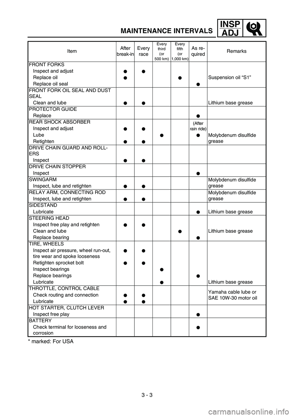
MAINTENANCE INTERVALS
* marked: For USA
FRONT FORKS
Inspect and adjust
Replace oil Suspension oil “S1”
Replace oil seal
FRONT FORK OIL SEAL AND DUST
SEAL
Clean and lube Lithium base grease
PROTECTOR GUIDE
Replace
REAR SHOCK ABSORBER
(After
rain ride)
Inspect and adjust
Lube
Molybdenum disulfide
grease
Retighten
DRIVE CHAIN GUARD AND ROLL-
ERS
Inspect
DRIVE CHAIN STOPPER
Inspect
SWINGARM
Molybdenum disulfide
grease
Inspect, lube and retighten
RELAY ARM, CONNECTING ROD
Molybdenum disulfide
grease
Inspect, lube and retighten
SIDESTAND
Lubricate Lithium base grease
STEERING HEAD
Inspect free play and retighten
Clean and lube Lithium base grease
Replace bearing
TIRE, WHEELS
Inspect air pressure, wheel run-out,
tire wear and spoke looseness
Retighten sprocket bolt
Inspect bearings
Replace bearings
Lubricate Lithium base grease
THROTTLE, CONTROL CABLE
Yamaha cable lube or
SAE 10W-30 motor oil Check routing and connection
Lubricate
HOT STARTER, CLUTCH LEVER
Inspect free play
BATTERY
Check terminal for looseness and
corrosionItemAfter
break-inEvery
race
Every
third
(or
500 km)Every
fifth
(or
1,000 km)As re-
quiredRemarks
Page 188 of 758
3 - 5
INSP
ADJ
EC350000
ENGINE
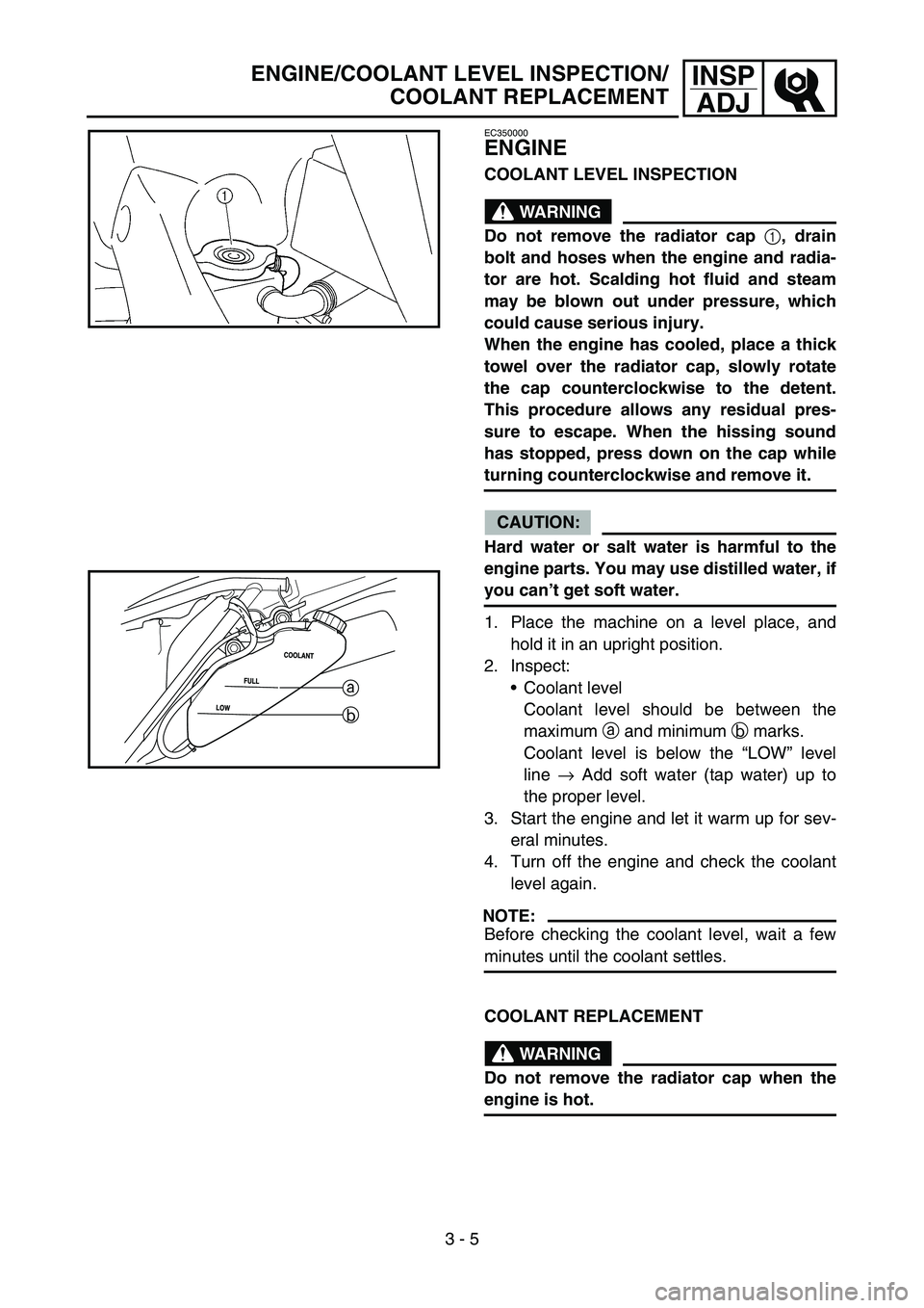
COOLANT LEVEL INSPECTION
WARNING
Do not remove the radiator cap
1, drain
bolt and hoses when the engine and radia-
tor are hot. Scalding hot fluid and steam
may be blown out under pressure, which
could cause serious injury.
When the engine has cooled, place a thick
towel over the radiator cap, slowly rotate
the cap counterclockwise to the detent.
This procedure allows any residual pres-
sure to escape. When the hissing sound
has stopped, press down on the cap while
turning counterclockwise and remove it.
CAUTION:
Hard water or salt water is harmful to the
engine parts. You may use distilled water, if
you can’t get soft water.
1. Place the machine on a level place, and
hold it in an upright position.
2. Inspect:
Coolant level
Coolant level should be between the
maximum a and minimum b marks.
Coolant level is below the “LOW” level
line → Add soft water (tap water) up to
the proper level.
3. Start the engine and let it warm up for sev-
eral minutes.
4. Turn off the engine and check the coolant
level again.
NOTE:
Before checking the coolant level, wait a few
minutes until the coolant settles.
a
b
COOLANT REPLACEMENT
WARNING
Do not remove the radiator cap when the
engine is hot.
ENGINE/COOLANT LEVEL INSPECTION/
COOLANT REPLACEMENT
Page 210 of 758
3 - 16
INSP
ADJ
ENGINE OIL REPLACEMENT
6. Idle the engine more than 10 seconds
while keeping the machine upright. Then
stop the engine and add the oil to the maxi-
mum level.
7. Install:
Oil tank cap
ENGINE OIL REPLACEMENT
1. Start the engine and let it warm up for sev-
eral minutes.
2. Stop the engine and place an oil pan under
the drain bolt.
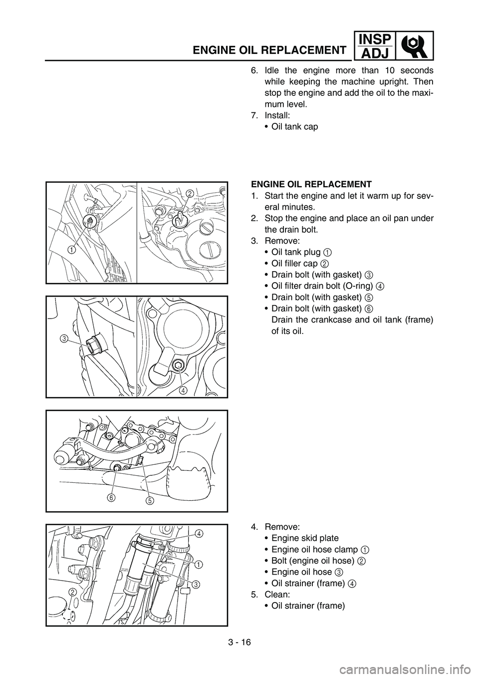
3. Remove:
Oil tank plug 1
Oil filler cap 2
Drain bolt (with gasket) 3
Oil filter drain bolt (O-ring) 4
Drain bolt (with gasket) 5
Drain bolt (with gasket) 6
Drain the crankcase and oil tank (frame)
of its oil.
4. Remove:
Engine skid plate
Engine oil hose clamp 1
Bolt (engine oil hose) 2
Engine oil hose 3
Oil strainer (frame) 4
5. Clean:
Oil strainer (frame)
Page 214 of 758
3 - 18
INSP
ADJ
IDLE SPEED ADJUSTMENT
10. Install:
Oil filler plug
11. Inspect:
Engine (for oil leaks)
Oil level
Refer to “ENGINE OIL LEVEL INSPEC-
TION”.
12. Check:
Oil pressure
EC35M021
IDLE SPEED ADJUSTMENT
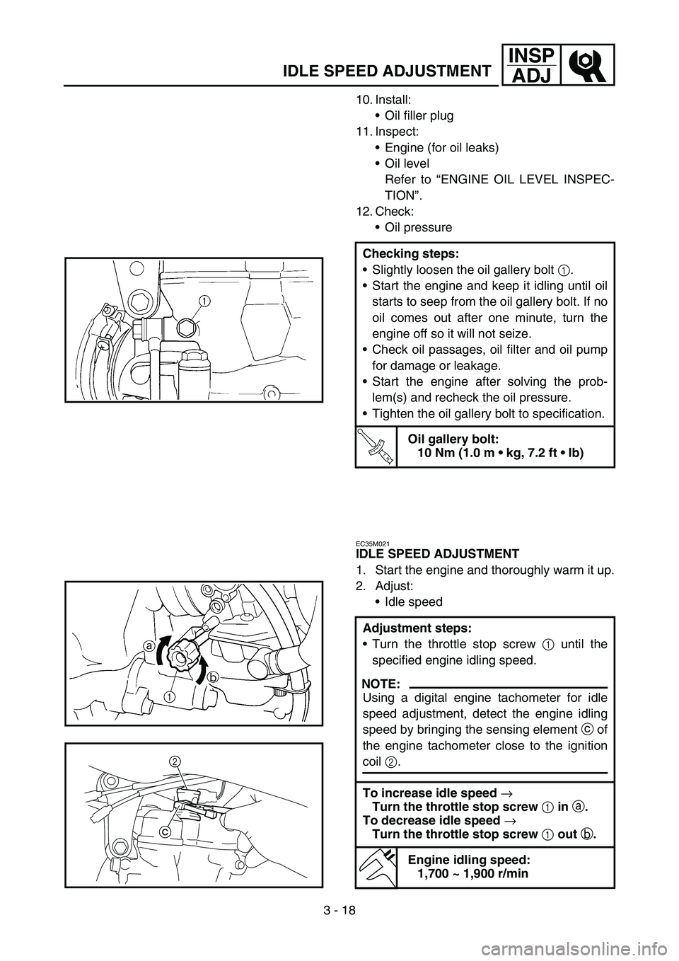
1. Start the engine and thoroughly warm it up.
2. Adjust:
Idle speed Checking steps:
Slightly loosen the oil gallery bolt 1.
Start the engine and keep it idling until oil
starts to seep from the oil gallery bolt. If no
oil comes out after one minute, turn the
engine off so it will not seize.
Check oil passages, oil filter and oil pump
for damage or leakage.
Start the engine after solving the prob-
lem(s) and recheck the oil pressure.
Tighten the oil gallery bolt to specification.
T R..
Oil gallery bolt:
10 Nm (1.0 m kg, 7.2 ft lb)
Adjustment steps:
Turn the throttle stop screw 1 until the
specified engine idling speed.
NOTE:
Using a digital engine tachometer for idle
speed adjustment, detect the engine idling
speed by bringing the sensing element c of
the engine tachometer close to the ignition
coil 2.
To increase idle speed
→
Turn the throttle stop screw
1 in
a.
To decrease idle speed
→
Turn the throttle stop screw
1 out
b.
Engine idling speed:
1,700 ~ 1,900 r/min
c2
Page 332 of 758
4 - 16
ENGCARBURETOR
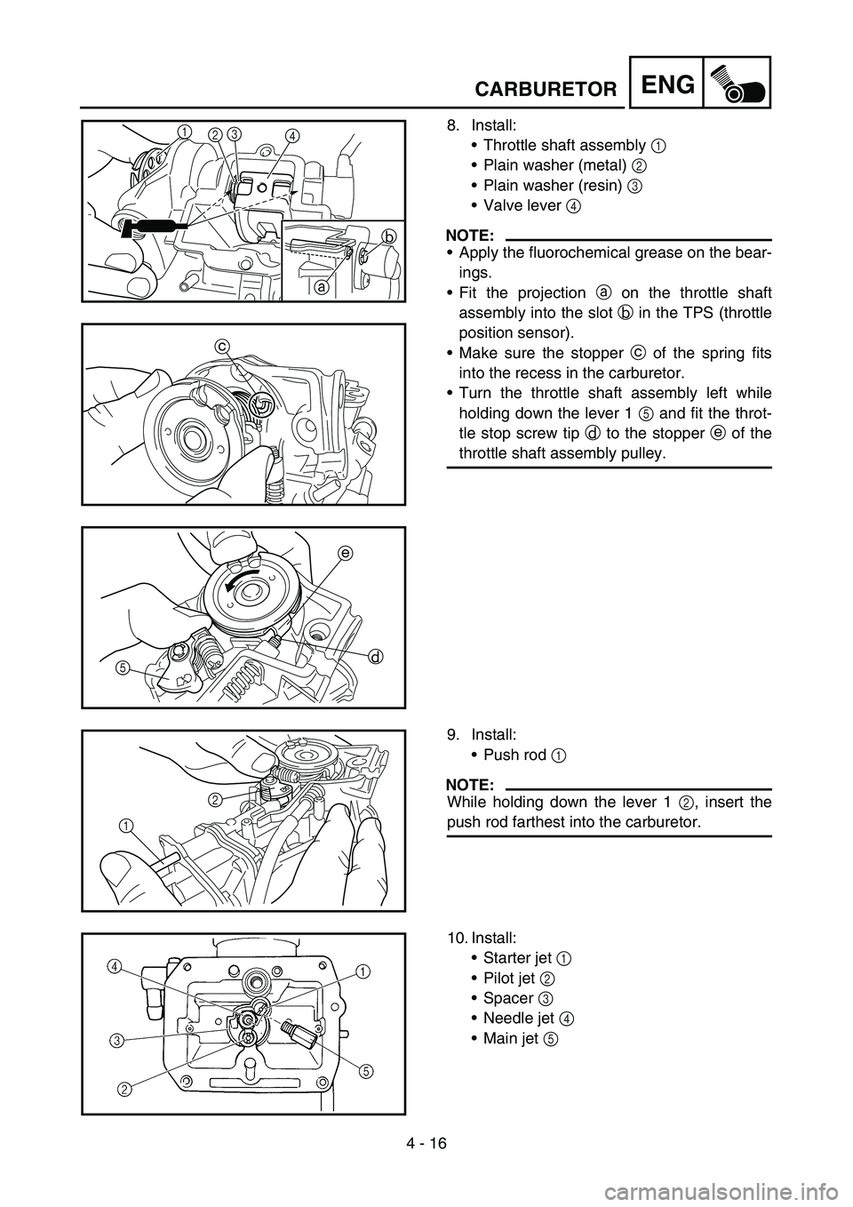
8. Install:
Throttle shaft assembly 1
Plain washer (metal) 2
Plain washer (resin) 3
Valve lever 4
NOTE:
Apply the fluorochemical grease on the bear-
ings.
Fit the projection a on the throttle shaft
assembly into the slot b in the TPS (throttle
position sensor).
Make sure the stopper c of the spring fits
into the recess in the carburetor.
Turn the throttle shaft assembly left while
holding down the lever 1 5 and fit the throt-
tle stop screw tip d to the stopper e of the
throttle shaft assembly pulley.
1
23
4
b
a
c
e
d
5
9. Install:
Push rod 1
NOTE:
While holding down the lever 1 2, insert the
push rod farthest into the carburetor.12
10. Install:
Starter jet 1
Pilot jet 2
Spacer 3
Needle jet 4
Main jet 5
Page 454 of 758
4 - 77
ENGKICK AXLE AND SHIFT SHAFT
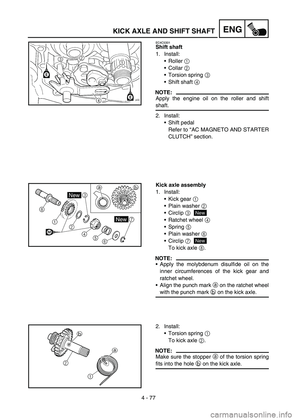
EC4C5301
Shift shaft
1. Install:
Roller 1
Collar 2
Torsion spring 3
Shift shaft 4
NOTE:
Apply the engine oil on the roller and shift
shaft.
2. Install:
Shift pedal
Refer to “AC MAGNETO AND STARTER
CLUTCH” section.
Kick axle assembly
1. Install:
Kick gear 1
Plain washer 2
Circlip 3
Ratchet wheel 4
Spring 5
Plain washer 6
Circlip 7
To kick axle 8.
NOTE:
Apply the molybdenum disulfide oil on the
inner circumferences of the kick gear and
ratchet wheel.
Align the punch mark a on the ratchet wheel
with the punch mark b on the kick axle.
New
New
2. Install:
Torsion spring 1
To kick axle 2.
NOTE:
Make sure the stopper a of the torsion spring
fits into the hole b on the kick axle.