stop start YAMAHA WR 450F 2005 Owners Manual
[x] Cancel search | Manufacturer: YAMAHA, Model Year: 2005, Model line: WR 450F, Model: YAMAHA WR 450F 2005Pages: 758, PDF Size: 17.3 MB
Page 26 of 758
GEN
INFO
1 - 1
DESCRIPTION
EC100000
GENERAL INFORMATION
EC110000
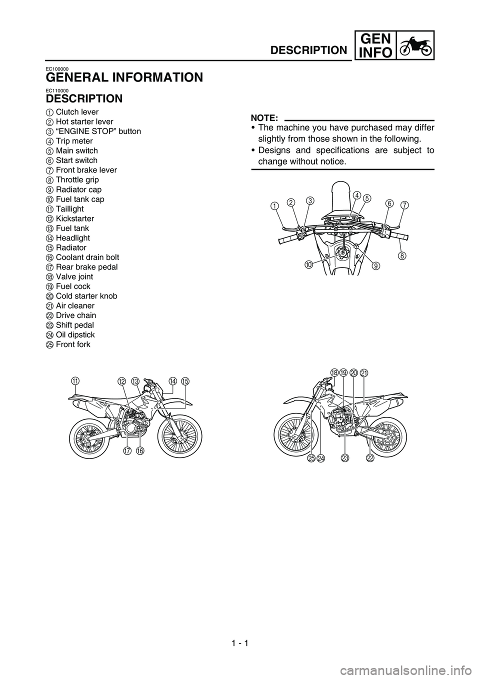
DESCRIPTION
1Clutch lever
2Hot starter lever
3“ENGINE STOP” button
4Trip meter
5Main switch
6Start switch
7Front brake lever
8Throttle grip
9Radiator cap
0Fuel tank cap
ATaillight
BKickstarter
CFuel tank
DHeadlight
ERadiator
FCoolant drain bolt
GRear brake pedal
HValve joint
IFuel cock
JCold starter knob
KAir cleaner
LDrive chain
MShift pedal
NOil dipstick
OFront forkNOTE:
The machine you have purchased may differ
slightly from those shown in the following.
Designs and specifications are subject to
change without notice.
A
BCD
E
F G
1234
5
6
7
8
9 0
HI
J
K
L M
N O
Page 27 of 758
GEN
INFO
ALLGEMEINE
ANGABEN
FAHRZEUGBESCHREI-
BUNG
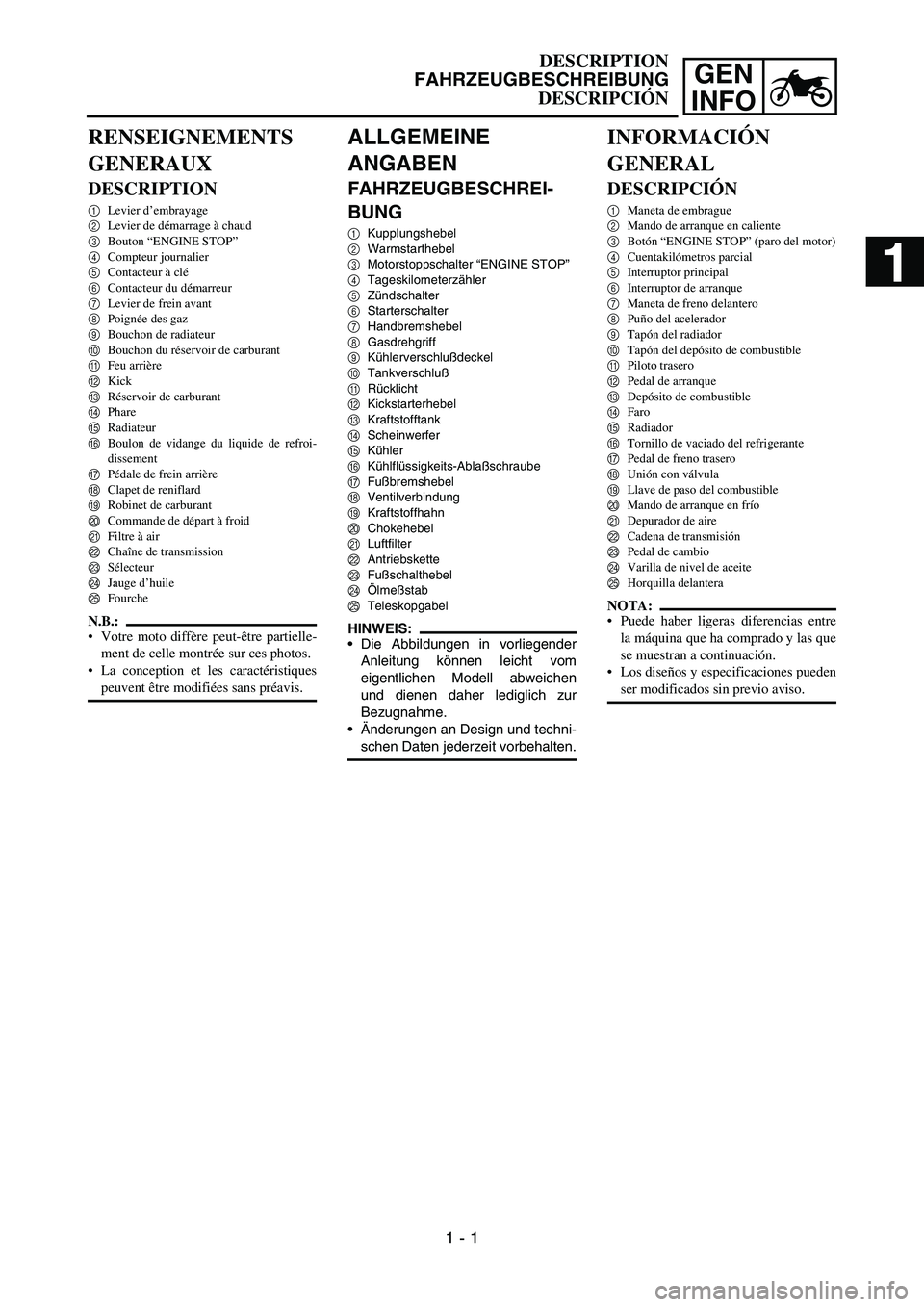
1Kupplungshebel
2Warmstarthebel
3Motorstoppschalter “ENGINE STOP”
4Tageskilometerzähler
5Zündschalter
6Starterschalter
7Handbremshebel
8Gasdrehgriff
9Kühlerverschlußdeckel
0Tankverschluß
ARücklicht
BKickstarterhebel
CKraftstofftank
DScheinwerfer
EKühler
FKühlflüssigkeits-Ablaßschraube
GFußbremshebel
HVentilverbindung
IKraftstoffhahn
JChokehebel
KLuftfilter
LAntriebskette
MFußschalthebel
NÖlmeßstab
OTeleskopgabel
HINWEIS:
Die Abbildungen in vorliegender
Anleitung können leicht vom
eigentlichen Modell abweichen
und dienen daher lediglich zur
Bezugnahme.
Änderungen an Design und techni-
schen Daten jederzeit vorbehalten.
RENSEIGNEMENTS
GENERAUX
DESCRIPTION
1Levier d’embrayage
2Levier de démarrage à chaud
3Bouton “ENGINE STOP”
4Compteur journalier
5Contacteur à clé
6Contacteur du démarreur
7Levier de frein avant
8Poignée des gaz
9Bouchon de radiateur
0Bouchon du réservoir de carburant
AFeu arrière
BKick
CRéservoir de carburant
DPhare
ERadiateur
FBoulon de vidange du liquide de refroi-
dissement
GPédale de frein arrière
HClapet de reniflard
IRobinet de carburant
JCommande de départ à froid
KFiltre à air
LChaîne de transmission
MSélecteur
NJauge d’huile
OFourche
N.B.:
Votre moto diffère peut-être partielle-
ment de celle montrée sur ces photos.
La conception et les caractéristiques
peuvent être modifiées sans préavis.
INFORMACIÓN
GENERAL
DESCRIPCIÓN
1Maneta de embrague
2Mando de arranque en caliente
3Botón “ENGINE STOP” (paro del motor)
4Cuentakilómetros parcial
5Interruptor principal
6Interruptor de arranque
7Maneta de freno delantero
8Puño del acelerador
9Tapón del radiador
0Tapón del depósito de combustible
APiloto trasero
BPedal de arranque
CDepósito de combustible
DFaro
ERadiador
FTornillo de vaciado del refrigerante
GPedal de freno trasero
HUnión con válvula
ILlave de paso del combustible
JMando de arranque en frío
KDepurador de aire
LCadena de transmisión
MPedal de cambio
NVarilla de nivel de aceite
OHorquilla delantera
NOTA:
Puede haber ligeras diferencias entre
la máquina que ha comprado y las que
se muestran a continuación.
Los diseños y especificaciones pueden
ser modificados sin previo aviso.
DESCRIPTION
FAHRZEUGBESCHREIBUNG
DESCRIPCIÓN
1 - 1
1
Page 50 of 758
1 - 10
GEN
INFO
CONTROL FUNCTIONS
EC150000
CONTROL FUNCTIONS
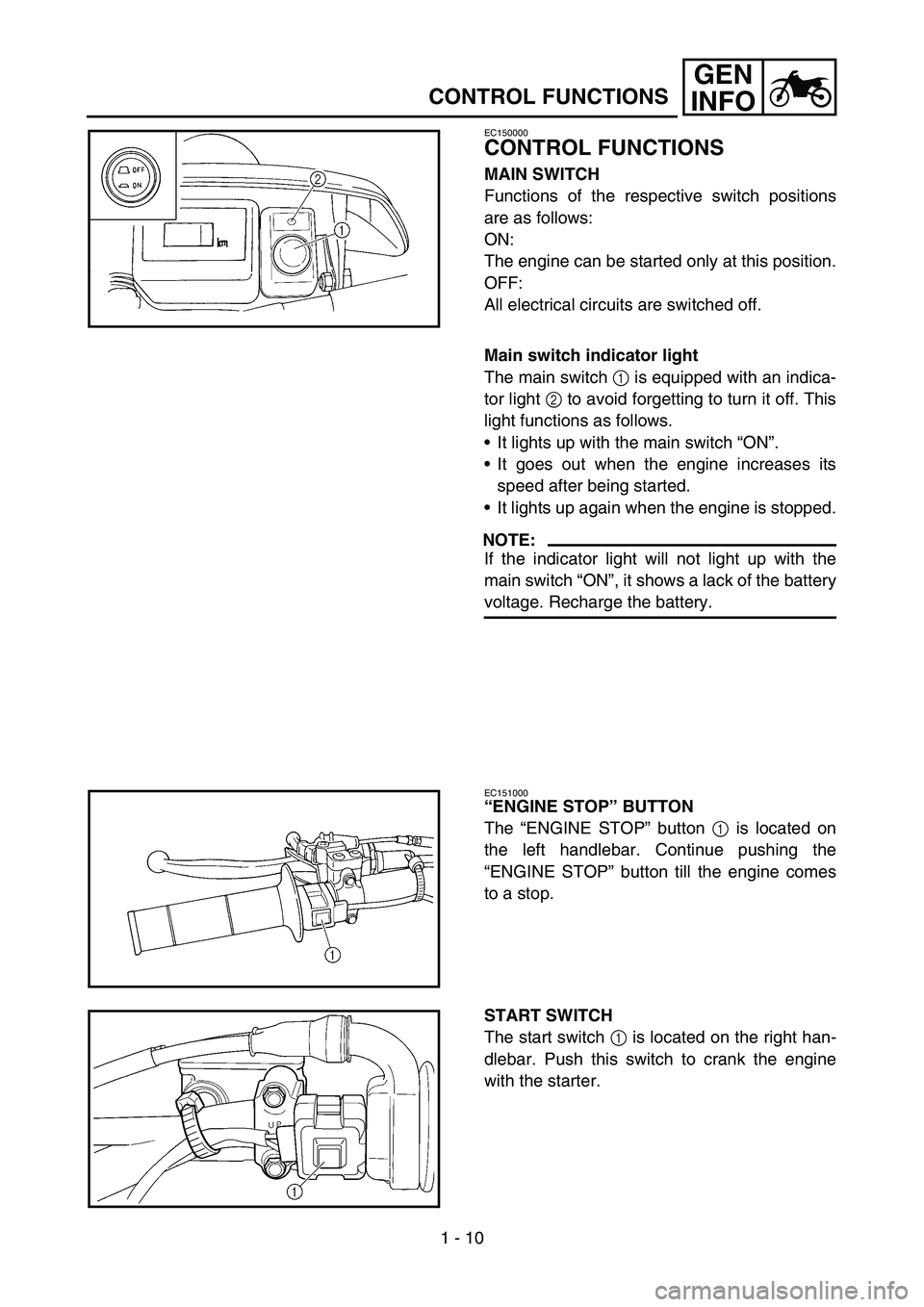
MAIN SWITCH
Functions of the respective switch positions
are as follows:
ON:
The engine can be started only at this position.
OFF:
All electrical circuits are switched off.
Main switch indicator light
The main switch 1 is equipped with an indica-
tor light 2 to avoid forgetting to turn it off. This
light functions as follows.
It lights up with the main switch “ON”.
It goes out when the engine increases its
speed after being started.
It lights up again when the engine is stopped.
NOTE:
If the indicator light will not light up with the
main switch “ON”, it shows a lack of the battery
voltage. Recharge the battery.
EC151000
“ENGINE STOP” BUTTON
The “ENGINE STOP” button 1 is located on
the left handlebar. Continue pushing the
“ENGINE STOP” button till the engine comes
to a stop.
START SWITCH
The start switch 1 is located on the right han-
dlebar. Push this switch to crank the engine
with the starter.
Page 51 of 758
GEN
INFO
BEDIENUNGSELEMENTE
UND DEREN FUNKTION
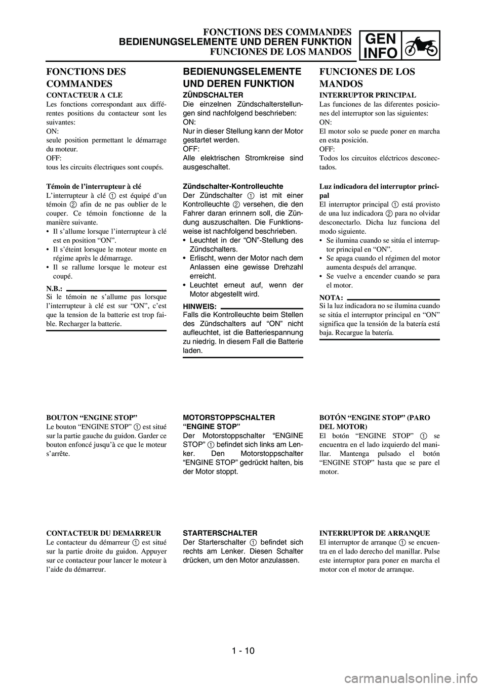
ZÜNDSCHALTER
Die einzelnen Zündschalterstellun-
gen sind nachfolgend beschrieben:
ON:
Nur in dieser Stellung kann der Motor
gestartet werden.
OFF:
Alle elektrischen Stromkreise sind
ausgeschaltet.
Zündschalter-Kontrolleuchte
Der Zündschalter 1 ist mit einer
Kontrolleuchte 2 versehen, die den
Fahrer daran erinnern soll, die Zün-
dung auszuschalten. Die Funktions-
weise ist nachfolgend beschrieben.
Leuchtet in der “ON”-Stellung des
Zündschalters.
Erlischt, wenn der Motor nach dem
Anlassen eine gewisse Drehzahl
erreicht.
Leuchtet erneut auf, wenn der
Motor abgestellt wird.
HINWEIS:
Falls die Kontrolleuchte beim Stellen
des Zündschalters auf “ON” nicht
aufleuchtet, ist die Batteriespannung
zu niedrig. In diesem Fall die Batterie
laden.
MOTORSTOPPSCHALTER
“ENGINE STOP”
Der Motorstoppschalter “ENGINE
STOP” 1 befindet sich links am Len-
ker. Den Motorstoppschalter
“ENGINE STOP” gedrückt halten, bis
der Motor stoppt.
STARTERSCHALTER
Der Starterschalter 1 befindet sich
rechts am Lenker. Diesen Schalter
drücken, um den Motor anzulassen.
FONCTIONS DES
COMMANDES
CONTACTEUR A CLE
Les fonctions correspondant aux diffé-
rentes positions du contacteur sont les
suivantes:
ON:
seule position permettant le démarrage
du moteur.
OFF:
tous les circuits électriques sont coupés.
Témoin de l’interrupteur à clé
L’interrupteur à clé 1 est équipé d’un
témoin 2 afin de ne pas oublier de le
couper. Ce témoin fonctionne de la
manière suivante.
Il s’allume lorsque l’interrupteur à clé
est en position “ON”.
Il s’éteint lorsque le moteur monte en
régime après le démarrage.
Il se rallume lorsque le moteur est
coupé.
N.B.:
Si le témoin ne s’allume pas lorsque
l’interrupteur à clé est sur “ON”, c’est
que la tension de la batterie est trop fai-
ble. Recharger la batterie.
BOUTON “ENGINE STOP”
Le bouton “ENGINE STOP” 1 est situé
sur la partie gauche du guidon. Garder ce
bouton enfoncé jusqu’à ce que le moteur
s’arrête.
CONTACTEUR DU DEMARREUR
Le contacteur du démarreur 1 est situé
sur la partie droite du guidon. Appuyer
sur ce contacteur pour lancer le moteur à
l’aide du démarreur.
FUNCIONES DE LOS
MANDOS
INTERRUPTOR PRINCIPAL
Las funciones de las diferentes posicio-
nes del interruptor son las siguientes:
ON:
El motor solo se puede poner en marcha
en esta posición.
OFF:
Todos los circuitos eléctricos desconec-
tados.
Luz indicadora del interruptor princi-
pal
El interruptor principal 1 está provisto
de una luz indicadora 2 para no olvidar
desconectarlo. Dicha luz funciona del
modo siguiente.
Se ilumina cuando se sitúa el interrup-
tor principal en “ON”.
Se apaga cuando el régimen del motor
aumenta después del arranque.
Se vuelve a encender cuando se para
el motor.
NOTA:
Si la luz indicadora no se ilumina cuando
se sitúa el interruptor principal en “ON”
significa que la tensión de la batería está
baja. Recargue la batería.
BOTÓN “ENGINE STOP” (PARO
DEL MOTOR)
El botón “ENGINE STOP” 1 se
encuentra en el lado izquierdo del mani-
llar. Mantenga pulsado el botón
“ENGINE STOP” hasta que se pare el
motor.
INTERRUPTOR DE ARRANQUE
El interruptor de arranque 1 se encuen-
tra en el lado derecho del manillar. Pulse
este interruptor para poner en marcha el
motor con el motor de arranque.
FONCTIONS DES COMMANDES
BEDIENUNGSELEMENTE UND DEREN FUNKTION
FUNCIONES DE LOS MANDOS
1 - 10
Page 54 of 758
1 - 12
GEN
INFO
CONTROL FUNCTIONS
EC157000
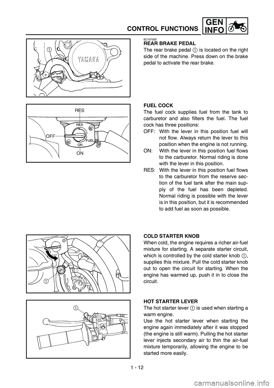
REAR BRAKE PEDAL
The rear brake pedal 1 is located on the right
side of the machine. Press down on the brake
pedal to activate the rear brake.
FUEL COCK
The fuel cock supplies fuel from the tank to
carburetor and also filters the fuel. The fuel
cock has three positions:
OFF: With the lever in this position fuel will
not flow. Always return the lever to this
position when the engine is not running.
ON: With the lever in this position fuel flows
to the carburetor. Normal riding is done
with the lever in this position.
RES: With the lever in this position fuel flows
to the carburetor from the reserve sec-
tion of the fuel tank after the main sup-
ply of the fuel has been depleted.
Normal riding is possible with the lever
is in this position, but it is recommended
to add fuel as soon as possible.
COLD STARTER KNOB
When cold, the engine requires a richer air-fuel
mixture for starting. A separate starter circuit,
which is controlled by the cold starter knob 1,
supplies this mixture. Pull the cold starter knob
out to open the circuit for starting. When the
engine has warmed up, push it in to close the
circuit.
HOT STARTER LEVER
The hot starter lever 1 is used when starting a
warm engine.
Use the hot starter lever when starting the
engine again immediately after it was stopped
(the engine is still warm). Pulling the hot starter
lever injects secondary air to thin the air-fuel
mixture temporarily, allowing the engine to be
started more easily.
Page 62 of 758
1 - 16
GEN
INFO
STARTING AND BREAK-IN
NOTE:
If the engine fails to start by pushing the start
switch, release the switch, wait a few seconds,
and then try again. Each starting attempt
should be as short as possible to preserve the
battery. Do not crank the engine more than
10 seconds on any one attempt. If the engine
does not start with the starter motor, try using
the kickstarter.
WARNING
If the starter motor will not turn when
pushing the start switch, stop pushing it
immediately and kick start the engine in
order to avoid the load on the motor.
Do not open the throttle while kicking the
kickstarter. Otherwise, the kickstarter
may kick back.
7. Return the cold starter knob to its original
position and run the engine at 3,000 ~
5,000 r/min for 1 or 2 minutes.
NOTE:
Since this model is equipped with an accelera-
tor pump, if the engine is raced (the throttle
opened and closed), the air/fuel mixture will be
too rich and the engine may stall. Also unlike a
two-stroke engine, this model can idle.
CAUTION:
Do not warm up the engine for extended
periods of time.
Page 65 of 758
GEN
INFO
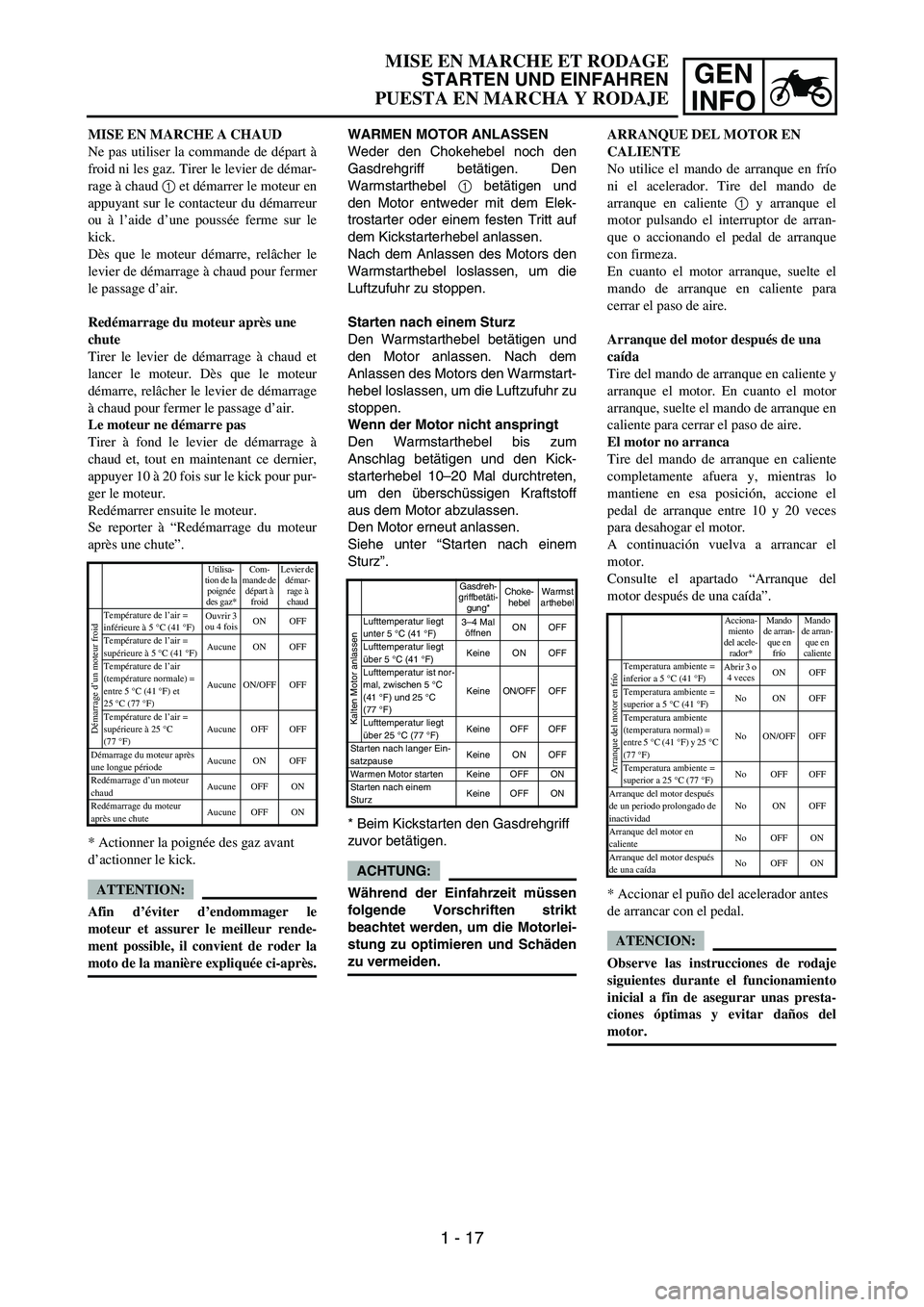
WARMEN MOTOR ANLASSEN
Weder den Chokehebel noch den
Gasdrehgriff betätigen. Den
Warmstarthebel 1 betätigen und
den Motor entweder mit dem Elek-
trostarter oder einem festen Tritt auf
dem Kickstarterhebel anlassen.
Nach dem Anlassen des Motors den
Warmstarthebel loslassen, um die
Luftzufuhr zu stoppen.
Starten nach einem Sturz
Den Warmstarthebel betätigen und
den Motor anlassen. Nach dem
Anlassen des Motors den Warmstart-
hebel loslassen, um die Luftzufuhr zu
stoppen.
Wenn der Motor nicht anspringt
Den Warmstarthebel bis zum
Anschlag betätigen und den Kick-
starterhebel 10–20 Mal durchtreten,
um den überschüssigen Kraftstoff
aus dem Motor abzulassen.
Den Motor erneut anlassen.
Siehe unter “Starten nach einem
Sturz”.
* Beim Kickstarten den Gasdrehgriff
zuvor betätigen.
ACHTUNG:
Während der Einfahrzeit müssen
folgende Vorschriften strikt
beachtet werden, um die Motorlei-
stung zu optimieren und Schäden
zu vermeiden.
Gasdreh-
griffbetäti-
gung*Choke-
hebelWarmst
arthebel
Kalten Motor anlassen
Lufttemperatur liegt
unter 5 °C (41 °F)3–4 Mal
öffnenON OFF
Lufttemperatur liegt
über 5 °C (41 °F)Keine ON OFF
Lufttemperatur ist nor-
mal, zwischen 5°C
(41°F) und 25°C
(77°F)Keine ON/OFF OFF
Lufttemperatur liegt
über 25 °C (77 °F)Keine OFF OFF
Starten nach langer Ein-
satzpauseKeine ON OFF
Warmen Motor starten Keine OFF ON
Starten nach einem
SturzKeine OFF ON
MISE EN MARCHE A CHAUD
Ne pas utiliser la commande de départ à
froid ni les gaz. Tirer le levier de démar-
rage à chaud 1 et démarrer le moteur en
appuyant sur le contacteur du démarreur
ou à l’aide d’une poussée ferme sur le
kick.
Dès que le moteur démarre, relâcher le
levier de démarrage à chaud pour fermer
le passage d’air.
Redémarrage du moteur après une
chute
Tirer le levier de démarrage à chaud et
lancer le moteur. Dès que le moteur
démarre, relâcher le levier de démarrage
à chaud pour fermer le passage d’air.
Le moteur ne démarre pas
Tirer à fond le levier de démarrage à
chaud et, tout en maintenant ce dernier,
appuyer 10 à 20 fois sur le kick pour pur-
ger le moteur.
Redémarrer ensuite le moteur.
Se reporter à “Redémarrage du moteur
après une chute”.
* Actionner la poignée des gaz avant
d’actionner le kick.
ATTENTION:
Afin d’éviter d’endommager le
moteur et assurer le meilleur rende-
ment possible, il convient de roder la
moto de la manière expliquée ci-après.
Utilisa-
tion de la
poignée
des gaz*Com-
mande de
départ à
froidLevier de
démar-
rage à
chaud
Démarrage d’un moteur froid
Température de l’air =
inférieure à 5 °C (41 °F)Ouvrir 3
ou 4 foisON OFF
Température de l’air =
supérieure à 5 °C (41 °F)Aucune ON OFF
Température de l’air
(température normale) =
entre 5°C (41°F) et
25°C (77°F)Aucune ON/OFF OFF
Température de l’air =
supérieure à 25 °C
(77°F)Aucune OFF OFF
Démarrage du moteur après
une longue périodeAucune ON OFF
Redémarrage d’un moteur
chaudAucune OFF ON
Redémarrage du moteur
après une chuteAucune OFF ON
ARRANQUE DEL MOTOR EN
CALIENTE
No utilice el mando de arranque en frío
ni el acelerador. Tire del mando de
arranque en caliente 1 y arranque el
motor pulsando el interruptor de arran-
que o accionando el pedal de arranque
con firmeza.
En cuanto el motor arranque, suelte el
mando de arranque en caliente para
cerrar el paso de aire.
Arranque del motor después de una
caída
Tire del mando de arranque en caliente y
arranque el motor. En cuanto el motor
arranque, suelte el mando de arranque en
caliente para cerrar el paso de aire.
El motor no arranca
Tire del mando de arranque en caliente
completamente afuera y, mientras lo
mantiene en esa posición, accione el
pedal de arranque entre 10 y 20 veces
para desahogar el motor.
A continuación vuelva a arrancar el
motor.
Consulte el apartado “Arranque del
motor después de una caída”.
* Accionar el puño del acelerador antes
de arrancar con el pedal.
ATENCION:
Observe las instrucciones de rodaje
siguientes durante el funcionamiento
inicial a fin de asegurar unas presta-
ciones óptimas y evitar daños del
motor.
Acciona-
miento
del acele-
rador*Mando
de arran-
que en
fríoMando
de arran-
que en
caliente
Arranque del motor en frío
Temperatura ambiente =
inferior a 5 °C (41 °F)Abrir 3 o
4 vecesON OFF
Temperatura ambiente =
superior a 5 °C (41 °F)No ON OFF
Temperatura ambiente
(temperatura normal) =
entre 5°C (41°F) y 25°C
(77°F)No ON/OFF OFF
Temperatura ambiente =
superior a 25 °C (77 °F)No OFF OFF
Arranque del motor después
de un periodo prolongado de
inactividadNo ON OFF
Arranque del motor en
calienteNo OFF ON
Arranque del motor después
de una caídaNo OFF ON
MISE EN MARCHE ET RODAGE
STARTEN UND EINFAHREN
PUESTA EN MARCHA Y RODAJE
1 - 17
Page 66 of 758
1 - 18
GEN
INFO
BREAK-IN PROCEDURES
1. Before starting the engine, fill the fuel tank
with the fuel.
2. Perform the pre-operation checks on the
machine.
3. Start and warm up the engine. Check the
idle speed, and check the operation of the
controls and the “ENGINE STOP” button.
Then, restart the engine and check its
operation within no more than 5 minutes
after it is restarted.
4. Operate the machine in the lower gears at
moderate throttle openings for five to eight
minutes.
5. Check how the engine runs when the
machine is ridden with the throttle 1/4 to 1/2
open (low to medium speed) for about one
hour.
6. Restart the engine and check the operation
of the machine throughout its entire operat-
ing range. Restart the machine and oper-
ate it for about 10 to 15 more minutes. The
machine will now be ready to race.
CAUTION:
After the break-in or before each race,
you must check the entire machine for
loose fittings and fasteners as per
“TORQUE-CHECK POINTS”.
Tighten all such fasteners as required.
When any of the following parts have
been replaced, they must be broken in.
CYLINDER AND CRANKSHAFT:
About one hour of break-in operation is
necessary.
PISTON, RING, VALVES, CAMSHAFTS
AND GEARS:
These parts require about 30 minutes of
break-in operation at half-throttle or less.
Observe the condition of the engine care-
fully during operation.
STARTING AND BREAK-IN
Page 67 of 758
GEN
INFO
EINFAHRVORSCHRIFTEN
1. Vor dem Starten volltanken.
2. Die “Routinekontrolle vor Fahrt-
beginn” ausführen.
3. Den Motor anlassen und einige
Minuten lang betreiben. Die Leer-
laufdrehzahl und die Funktion der
Bedienelemente einschließlich des
Motorstoppschalters “ENGINE
STOP” kontrollieren. Den Motor
erneut anlassen und innerhalb 5
Minuten dessen Funktion kontrol-
lieren.
4. Das Motorrad 5–8 Minuten lang
mit mäßigem Gas im unteren
Gangbereich betreiben.
5. Den Motorbetrieb bei 1/4 bis 1/2
geöffnetem Gasdrehgriff (niedri-
ger bis mäßiger Geschwindig-
keit) etwa eine Stunde lang
überwachen.
6. Den Motor erneut starten und
den gesamten Betriebsbereich
kontrollieren. Den Motor erneut
starten und weiter 10–15 Minu-
ten lang betreiben. Das Motorrad
ist nun rennfertig.
ACHTUNG:
Entsprechend dem Abschnitt
“ANZUGSDREHMOMENTE
KONTROLLIEREN”, nach dem
Einfahren sowie vor jedem Ren-
nen sämtliche Befestigungsele-
mente kontrollieren.
Befestigungselemente ggf. vor-
schriftsmäßig festziehen.
Folgende Bauteile müssen nach
dem Auswechseln eingefahren
werden.
ZYLINDER UND KURBEL-
WELLE:
Eine einstündige Einfahrzeit ein-
legen.
KOLBEN, KOLBENRINGE, VEN-
TILE, NOCKLENWELLEN UND
RITZEL:
Eine halbstündige Einfahrzeit
mit maximal halb geöffnetem
Gasdrehgriff einlegen. Den
Motorbetrieb gründlich überwa-
chen. PROCEDURE DE RODAGE
1. Avant de démarrer le moteur, faire
le plein du réservoir de carburant.
2. Effectuer les contrôles avant utilisa-
tion.
3. Mettre le moteur en marche et le
laisser chauffer. Contrôler le régime
de ralenti et le bon fonctionnement
des commandes et du bouton
“ENGINE STOP”. Redémarrer
ensuite le moteur et contrôler son
fonctionnement dans les 5 minutes
maximum qui suivent son redémar-
rage.
4. Rouler pendant cinq à huit minutes
sur les rapports inférieurs et à
régime modéré.
5. Contrôler le fonctionnement du
moteur lorsque la moto est utilisée
pendant une heure environ aux régi-
mes bas à moyens (ouverture des
gaz 1/4 à 1/2).
6. Remettre le moteur en marche et
vérifier le fonctionnement de la
moto à toutes les vitesses. Redémar-
rer la moto et rouler pendant 10 à 15
minutes environ. La moto est main-
tenant prête pour la course.
ATTENTION:
Après le rodage ou avant chaque
course, il est indispensable de con-
trôler le bon serrage des raccords et
des fixations conformément aux ins-
tructions de la section “POINTS DE
VERIFICATION DES COUPLES
DE SERRAGE”.
Resserrer au couple requis tout élé-
ment desserré.
Si l’une quelconque des pièces sui-
vantes a été remplacée, un nouveau
rodage est nécessaire.
CYLINDRE ET VILEBREQUIN:
Roder pendant environ une heure.
PISTON, SEGMENT, SOUPAPES,
ARBRES A CAMES ET
PIGNONS:
Ces pièces nécessitent un rodage
d’environ 30 minutes à une ouver-
ture des gaz de 1/2 au maximum.
Surveiller attentivement l’état du
moteur pendant le rodage.PROCEDIMIENTO DE RODAJE
1. Antes de poner en marcha el motor
llene el depósito de combustible.
2. Realice las comprobaciones previas
de la máquina.
3. Arranque y caliente el motor. Com-
pruebe el ralentí, así como el fun-
cionamiento de los mandos y el
botón “ENGINE STOP”. A conti-
nuación vuelva a arrancar el motor
y compruebe su funcionamiento
durante no más de 5 minutos des-
pués de arrancar.
4. Utilice la máquina en marchas cor-
tas y a regímenes moderados
durante cinco a ocho minutos.
5. Observe cómo funciona el motor
con el gas entre 1/4 y 1/2 (régimen
entre bajo y medio) durante aproxi-
madamente una hora.
6. Vuelva a arrancar el motor y com-
pruebe el funcionamiento de la
máquina en todos los regímenes.
Vuelva a arrancar la máquina y uti-
lícela durante 10 o 15 minutos más.
La máquina ya está preparada para
competir.
ATENCION:
Después del rodaje o antes de cada
carrera debe comprobar toda la
máquina para detectar piezas o
sujeciones flojas, conforme a “PUN-
TOS DE COMPROBACIÓN DE
APRIETE”.
Apriete todas las sujeciones según
sea necesario.
Las piezas siguientes, si se cambian,
deben pasar el rodaje.
CILINDRO Y CIGÜEÑAL:
Requieren aproximadamente una
hora de rodaje.
PISTÓN, ARO, VÁLVULAS, EJES
DE LEVAS Y ENGRANAJES:
Estas piezas requieren aproximada-
mente 30 minutos de rodaje a medio
gas o menos. Observe atentamente
el estado del motor durante el fun-
cionamiento.
MISE EN MARCHE ET RODAGE
STARTEN UND EINFAHREN
PUESTA EN MARCHA Y RODAJE
1 - 18
Page 74 of 758
1 - 21
GEN
INFO
CLEANING AND STORAGE
8. Automotive wax may be applied to all
painted or chromed surfaces. Avoid combi-
nation cleaner-waxes, as they may contain
abrasives.
9. After completing the above, start the
engine and allow it to idle for several min-
utes.
EC1B2001
STORAGE
If your machine is to be stored for 60 days or
more, some preventive measures must be
taken to avoid deterioration. After cleaning the
machine thoroughly, prepare it for storage as
follows:
1. Drain the fuel tank, fuel lines, and the car-
buretor float bowl.
2. Remove the spark plug, pour a tablespoon
of SAE 10W-30 motor oil in the spark plug
hole, and reinstall the plug. With the engine
stop switch pushed in, kick the engine over
several times to coat the cylinder walls with
oil.
3. Remove the drive chain, clean it thoroughly
with solvent, and lubricate it. Reinstall the
chain or store it in a plastic bag tied to the
frame.
4. Lubricate all control cables.
5. Block the frame up to raise the wheels off
the ground.
6. Tie a plastic bag over the exhaust pipe out-
let to prevent moisture from entering.
7. If the machine is to be stored in a humid or
salt-air environment, coat all exposed
metal surfaces with a film of light oil. Do not
apply oil to rubber parts or the seat cover.
NOTE:
Make any necessary repairs before the
machine is stored.