warning YAMAHA WR 450F 2005 Service Manual
[x] Cancel search | Manufacturer: YAMAHA, Model Year: 2005, Model line: WR 450F, Model: YAMAHA WR 450F 2005Pages: 758, PDF Size: 17.3 MB
Page 590 of 758

5 - 40
CHAS
EC5B3000
REMOVAL POINTS
EC5B3100
Master cylinder
1. Remove:
Master cylinder bracket 1
Master cylinder 2
CAUTION:
Do not let the master cylinder hang on the
brake hose.
Keep the master cylinder cap side hori-
zontal to prevent air from coming in.
EC5B3200
Grip
1. Remove:
Grip 1
NOTE:
Blow in air between the handlebar or tube
guide and the grip. Then remove the grip
which has become loose.
EC5B4000
INSPECTION
EC5B4100
Handlebar
1. Inspect:
Handlebar 1
Bends/cracks/damage → Replace.
WARNING
Do not attempt to straighten a bent handle-
bar as this may dangerously weaken the
handlebar.
HANDLEBAR
Page 596 of 758

5 - 43
CHASHANDLEBAR
6. Install:
Throttle cable cap 1
Screw (throttle cable cap) 2
WARNING
After tightening the screws, check that the
throttle grip
3 moves smoothly. If it does
not, retighten the bolts for adjustment.
T R..4 Nm (0.4 m · kg, 2.9 ft · lb)
7. Install:
Cover (grip cap) 1
Cover (throttle cable cap) 2
8. Install:
Start switch 1
Master cylinder 2
Master cylinder bracket 3
Bolt (master cylinder bracket) 4
Clamp 5
NOTE:
The start switch and master cylinder bracket
should be installed according to the dimen-
sions shown.
Install the bracket so that the arrow mark a
faces upward.
First tighten the bolt on the upper side of the
master cylinder bracket, and then tighten the
bolt on the lower side.
T R..9 Nm (0.9 m · kg, 6.5 ft · lb)
Zero mm
(Zero in)Zero mm
(Zero in)
Page 602 of 758

5 - 46
CHAS
EC560000
STEERING
Extent of removal:
1 Under bracket removal
2 Bearing removal
Extent of removal Order Part name Q’ty Remarks
STEERING REMOVAL
WARNING
Support the machine securely so there is nodanger of it falling over.
Preparation for removal Hold the machine by placing the
suitable stand under the engine.
Headlight
Handlebar Refer to “HANDLEBAR” section.
Hose guide
Front fender
1 Coupler bracket 1
2 Trip meter 1
3 Main switch 1 Disconnect the main switch lead.
4 Steering shaft cap 1
5 Steering shaft nut 1
6 Front fork 2 Refer to “FRONT FORK” section.
7 Handle crown 1
8 Ring nut 1 Use special tool.
Refer to “REMOVAL POINTS”.
9 Under bracket 1
10 Bearing race cover 1
21
STEERING
Page 606 of 758

5 - 48
CHAS
EC563000
REMOVAL POINTS
EC563202
Ring nut
1. Remove:
Ring nut 1
Use the ring nut wrench 2.
WARNING
Support the steering shaft so that it may
not fall down.
Ring nut wrench:
YU-33975/90890-01403
EC563300
Bearing (lower)
1. Remove:
Bearing (lower) 1
Use the floor chisel 2.
CAUTION:
Take care not to damage the steering shaft
thread.
Bearing race
1. Remove:
Bearing race 1
Remove the bearing race using long rod
2 and the hammer.
EC564000
INSPECTION
EC564200
Steering shaft
1. Inspect:
Steering shaft 1
Bend/damage → Replace.
STEERING
Page 614 of 758

5 - 52
CHASSWINGARM
EC570000
SWINGARM
Extent of removal:
1 Swingarm removal
Extent of removal Order Part name Q’ty Remarks
SWINGARM REMOVAL
WARNING
Support the machine securely so there is nodanger of it falling over.
Preparation for removal Hold the machine by placing the
suitable stand under the engine.
Brake hose holder
Refer to “FRONT BRAKE AND REAR
BRAKE” section.
Rear caliper
Bolt (brake pedal) Shift the brake pedal backward.
Drive chain
1 Chain support 1
2 Chain tensioner (lower) 1
3 Bolt (rear shock absorber-relay
arm)1 Hold the swingarm.
4 Bolt (connecting rod) 1
5 Pivot shaft 1
6 Swingarm 1
1
Page 630 of 758

5 - 60
CHASREAR SHOCK ABSORBER
EC580000
REAR SHOCK ABSORBER
Extent of removal:
1 Rear shock absorber removal
2 Rear shock absorber disassembly
Extent of removal Order Part name Q’ty Remarks
REAR SHOCK ABSORBER
REMOVAL
WARNING
Support the machine securely so there is nodanger of it falling over.Preparation for removal Hold the machine by placing the
suitable stand under the engine.
Seat, fitting band and side covers Refer to “SEAT, FUEL TANK AND SIDE
COVERS” section in the CHAPTER 4.
Air filter cover Refer to “AIR FILTER CLEANING” sec-
tion in the CHAPTER 3.
Silencer Refer to “EXHAUST PIPE AND
SILENCER” section in the CHAPTER 4.
Drain the coolant. Refer to “COOLANT REPLACEMENT”
section in the CHAPTER 3.
Coolant reservoir tank breather
hoseDisconnect at the coolant reservoir tank
side.
Coolant reservoir hose Disconnect at the coolant reservoir tank
side.
Air induction hose (air cut-off
valve-air filter case)Disconnect at the air filter case side.
Page 636 of 758

5 - 63
CHAS
EC586000
HANDLING NOTE
WARNING
This shock absorber is provided with a
separate type tank filled with high-pressure
nitrogen gas. To prevent the danger of
explosion, read and understand the follow-
ing information before handling the shock
absorber.
The manufacturer can not be held respon-
sible for property damage or personal
injury that may result from improper han-
dling.
1. Never tamper or attempt to disassemble
the cylinder or the tank.
2. Never throw the shock absorber into an
open flame or other high heat. The
shock absorber may explode as a result
of nitrogen gas expansion and/or dam-
age to the hose.
3. Be careful not to damage any part of the
gas tank. A damaged gas tank will impair
the damping performance or cause a
malfunction.
4. Take care not to scratch the contact sur-
face of the piston rod with the cylinder;
or oil could leak out.
5. Never attempt to remove the plug at the
bottom of the nitrogen gas tank. It is
very dangerous to remove the plug.
6. When scrapping the shock absorber, fol-
low the instructions on disposal.
EC587000
NOTES ON DISPOSAL (YAMAHA DEALERS
ONLY)
Before disposing the shock absorber, be sure
to extract the nitrogen gas from valve 1. Wear
eye protection to prevent eye damage from
escaping gas and/or metal chips.
WARNING
To dispose of a damaged or worn-out
shock absorber, take the unit to your
Yamaha dealer for this disposal procedure.
REAR SHOCK ABSORBER
Page 670 of 758
6 - 9
–+ELECELECTRIC STARTING SYSTEM
EC624000
COUPLERS AND LEADS CONNECTION
INSPECTION
1. Check:
Couplers and leads connection
Rust/dust/looseness/short-circuit →
Repair or replace.
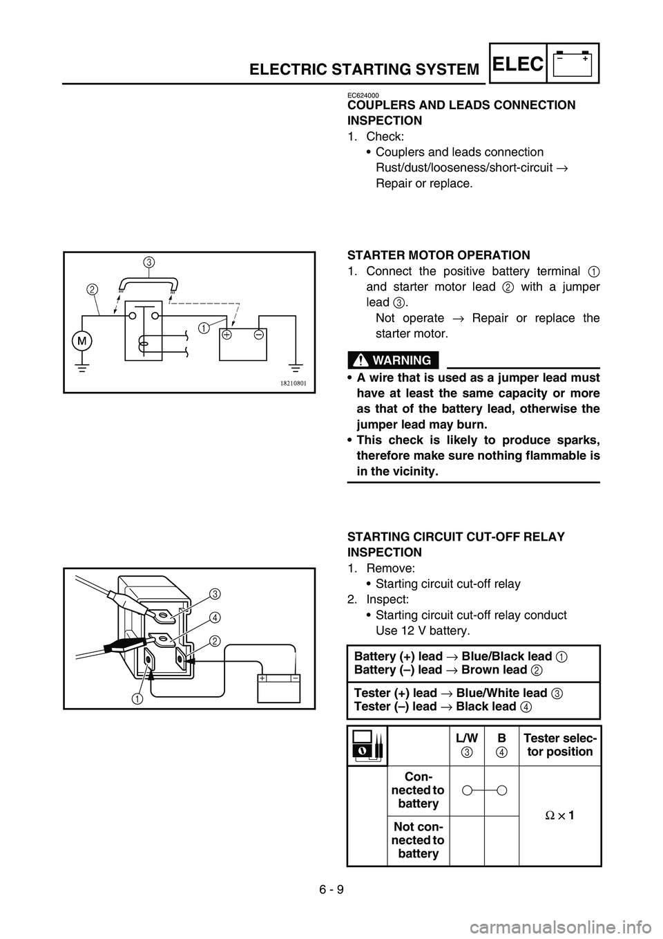
STARTER MOTOR OPERATION
1. Connect the positive battery terminal 1
and starter motor lead 2 with a jumper
lead 3.
Not operate → Repair or replace the
starter motor.
WARNING
A wire that is used as a jumper lead must
have at least the same capacity or more
as that of the battery lead, otherwise the
jumper lead may burn.
This check is likely to produce sparks,
therefore make sure nothing flammable is
in the vicinity.
STARTING CIRCUIT CUT-OFF RELAY
INSPECTION
1. Remove:
Starting circuit cut-off relay
2. Inspect:
Starting circuit cut-off relay conduct
Use 12 V battery.
Battery (+) lead
→ Blue/Black lead
1
Battery (–) lead
→ Brown lead
2
Tester (+) lead
→ Blue/White lead
3
Tester (–) lead
→ Black lead
4
L/W
3 B
4 Tester selec-
tor position
Con-
nected to
battery
Ω
×
×× × 1
Not con-
nected to
battery
2 4
3
1
Page 710 of 758
7 - 1
TUN
EC700000
TUNING
EC710000
ENGINE
Carburetor setting
The air/fuel mixture will vary depending on
atmospheric conditions. Therefore, it is nec-
essary to take into consideration the air pres-
sure, ambient temperature, humidity, etc.,
when adjusting the carburetor.
Perform a test run to check for proper engine
performance (e.g., throttle response) and
spark plug(-s) discoloration or fouling. Use
these readings to determine the best possi-
ble carburetor setting.
NOTE:
It is recommended to keep a record of all car-
buretor settings and external conditions (e.g.,
atmospheric conditions, track/surface condi-
tions, lap times) to make future carburetor set-
ting easier.
WARNING
The carburetor is a part of the fuel line.
Therefore, be sure to install it in a well-
ventilated area, away from flammable
objects and any sources of fire.
Never look into the carburetor intake.
Flames may shoot out from the pipe if the
engine backfires while it is being started.
Gasoline may be discharged from the
accelerator pump nozzle when the carbu-
retor has been removed.
SETTING
Page 734 of 758

7 - 12
TUNSETTING
EC727020
Spring preload adjustment
The spring preload is adjusted by installing the
adjustment washer 1 between the fork spring
2 and damper rod 3.
CAUTION:
Do not install three or more adjustment
washers for each front fork.
WARNING
Always adjust each front fork to the same
setting. Uneven adjustment can cause poor
handling and loss of stability.
ÈLoad
ÉFork stroke
1Without adjustment washer (standard)
21 adjustment washer
32 adjustment washers
Standard washer quantity:
Zero adjustment washers
Extent of adjustment:
Zero ~ 2 adjustment washers
EC72A001
Setting of spring after replacement
As the front fork setting can be easily affected
by rear suspension, take care so that the
machine front and rear are balanced (in posi-
tion, etc.) when setting the front fork.
1. Use of soft spring
Generally a soft spring gives a soft riding
feeling. Rebound damping tends to
become stronger and the front fork may
sink deeply over a series of gaps.
To set a soft spring:
Change the rebound damping.
Turn out one or two clicks.
Change the compression damping.
Turn in one or two clicks.