wheel YAMAHA WR 450F 2006 Manuale de Empleo (in Spanish)
[x] Cancel search | Manufacturer: YAMAHA, Model Year: 2006, Model line: WR 450F, Model: YAMAHA WR 450F 2006Pages: 786, tamaño PDF: 22.49 MB
Page 284 of 786

3 - 44
INSP
ADJ
STEERING HEAD INSPECTION AND ADJUSTMENT
2. Inspect:
Bearing free play
Exist play → Replace.
STEERING HEAD INSPECTION AND
ADJUSTMENT
1. Elevate the front wheel by placing a suit-
able stand under the engine.
2. Check:
Steering shaft
Grasp the bottom of the forks and gently
rock the fork assembly back and forth.
Free play → Adjust steering head.
3. Check:
Steering smooth action
Turn the handlebar lock to lock.
Unsmooth action → Adjust steering ring
nut.
4. Adjust:
Steering ring nut
Steering ring nut adjustment steps:
Remove the headlight.
Remove the handlebar and handle crown.
Loosen the ring nut 1 using the ring nut
wrench 2.
Ring nut wrench:
YU-33975/90890-01403
Page 460 of 786
4 - 72
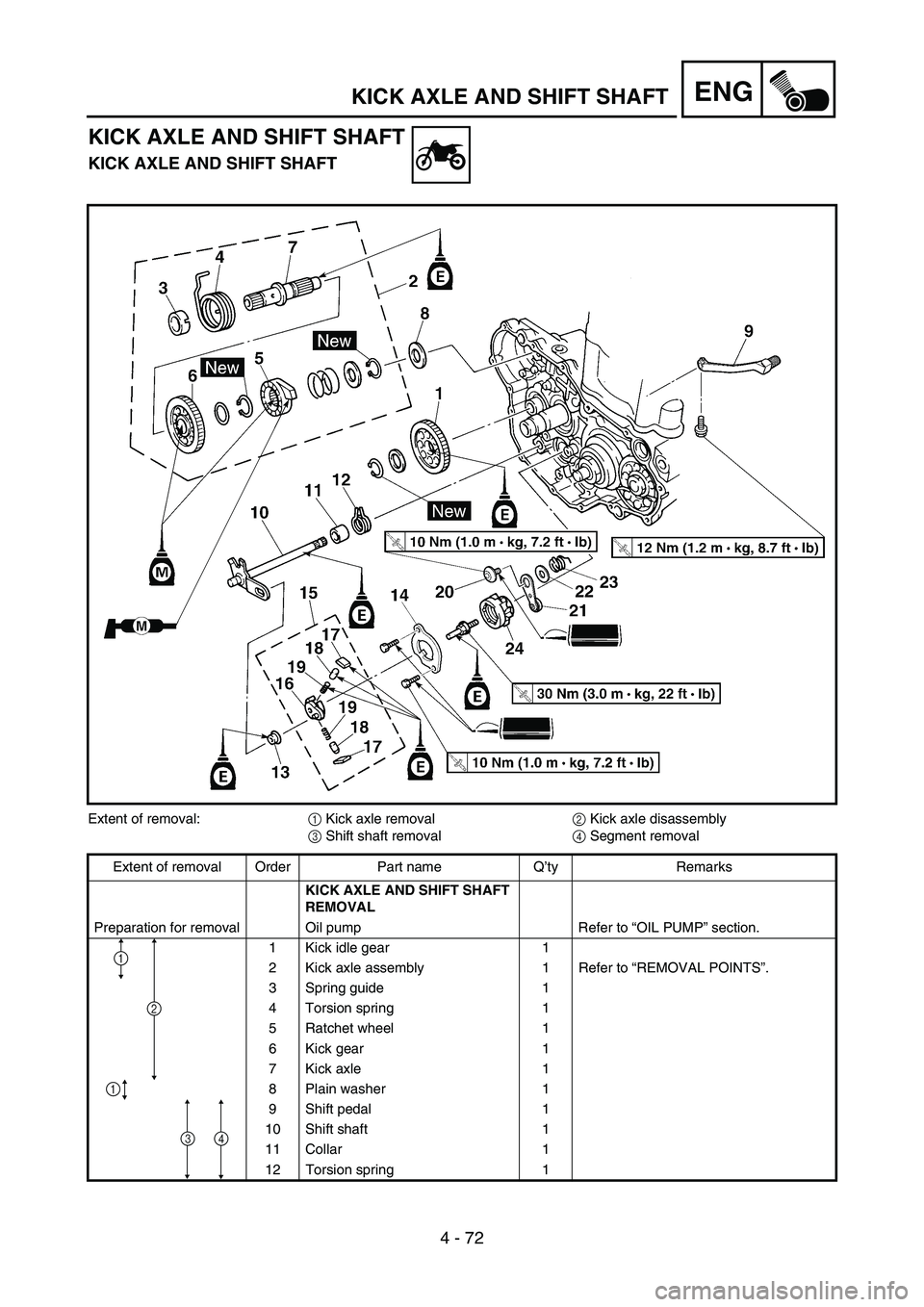
ENGKICK AXLE AND SHIFT SHAFT
KICK AXLE AND SHIFT SHAFT
KICK AXLE AND SHIFT SHAFT
Extent of removal:
1 Kick axle removal
2 Kick axle disassembly
3 Shift shaft removal
4 Segment removal
Extent of removal Order Part name Q’ty Remarks
KICK AXLE AND SHIFT SHAFT
REMOVAL
Preparation for removal Oil pump Refer to “OIL PUMP” section.
1 Kick idle gear 1
2 Kick axle assembly 1 Refer to “REMOVAL POINTS”.
3 Spring guide 1
4 Torsion spring 1
5 Ratchet wheel 1
6 Kick gear 1
7 Kick axle 1
8 Plain washer 1
9 Shift pedal 1
10 Shift shaft 1
11 Collar 1
12 Torsion spring 1
1
1
2
34
Page 464 of 786
4 - 74
ENGKICK AXLE AND SHIFT SHAFT
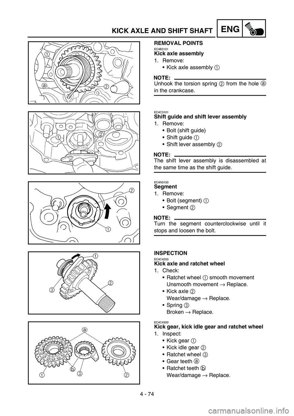
REMOVAL POINTS
EC4B3101
Kick axle assembly
1. Remove:
Kick axle assembly 1
NOTE:
Unhook the torsion spring 2 from the hole a
in the crankcase.
EC4C3101
Shift guide and shift lever assembly
1. Remove:
Bolt (shift guide)
Shift guide 1
Shift lever assembly 2
NOTE:
The shift lever assembly is disassembled at
the same time as the shift guide.
EC4N3100
Segment
1. Remove:
Bolt (segment) 1
Segment 2
NOTE:
Turn the segment counterclockwise until it
stops and loosen the bolt.
INSPECTION
EC4C4200
Kick axle and ratchet wheel
1. Check:
Ratchet wheel 1 smooth movement
Unsmooth movement → Replace.
Kick axle 2
Wear/damage → Replace.
Spring 3
Broken → Replace.
EC4C4300
Kick gear, kick idle gear and ratchet wheel
1. Inspect:
Kick gear 1
Kick idle gear 2
Ratchet wheel 3
Gear teeth a
Ratchet teeth b
Wear/damage → Replace.
Page 470 of 786
4 - 77
ENGKICK AXLE AND SHIFT SHAFT
EC4C5301
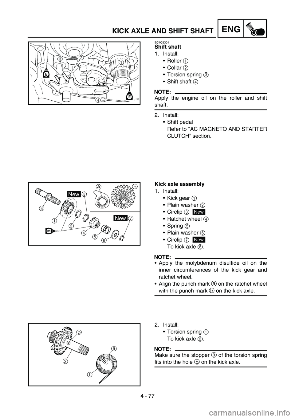
Shift shaft
1. Install:
Roller 1
Collar 2
Torsion spring 3
Shift shaft 4
NOTE:
Apply the engine oil on the roller and shift
shaft.
2. Install:
Shift pedal
Refer to “AC MAGNETO AND STARTER
CLUTCH” section.
Kick axle assembly
1. Install:
Kick gear 1
Plain washer 2
Circlip 3
Ratchet wheel 4
Spring 5
Plain washer 6
Circlip 7
To kick axle 8.
NOTE:
Apply the molybdenum disulfide oil on the
inner circumferences of the kick gear and
ratchet wheel.
Align the punch mark a on the ratchet wheel
with the punch mark b on the kick axle.
New
New
2. Install:
Torsion spring 1
To kick axle 2.
NOTE:
Make sure the stopper a of the torsion spring
fits into the hole b on the kick axle.
Page 472 of 786
4 - 78
ENGKICK AXLE AND SHIFT SHAFT
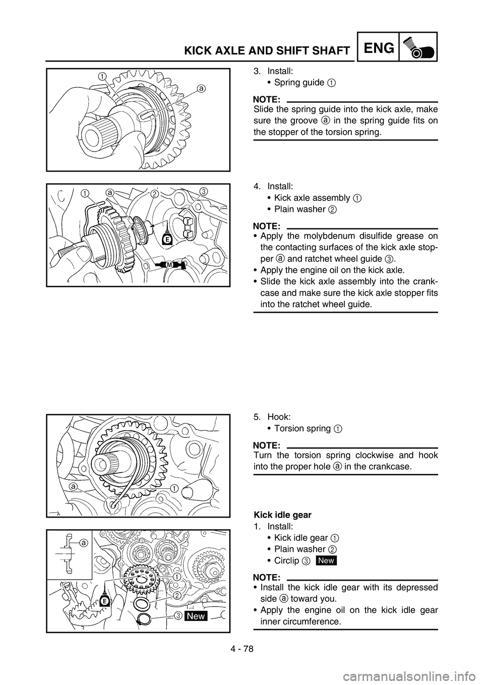
3. Install:
Spring guide 1
NOTE:
Slide the spring guide into the kick axle, make
sure the groove a in the spring guide fits on
the stopper of the torsion spring.
4. Install:
Kick axle assembly 1
Plain washer 2
NOTE:
Apply the molybdenum disulfide grease on
the contacting surfaces of the kick axle stop-
per a and ratchet wheel guide 3.
Apply the engine oil on the kick axle.
Slide the kick axle assembly into the crank-
case and make sure the kick axle stopper fits
into the ratchet wheel guide.
5. Hook:
Torsion spring 1
NOTE:
Turn the torsion spring clockwise and hook
into the proper hole a in the crankcase.
Kick idle gear
1. Install:
Kick idle gear 1
Plain washer 2
Circlip 3
NOTE:
Install the kick idle gear with its depressed
side a toward you.
Apply the engine oil on the kick idle gear
inner circumference.
New
Page 474 of 786
4 - 79
ENGAC MAGNETO AND STARTER CLUTCH
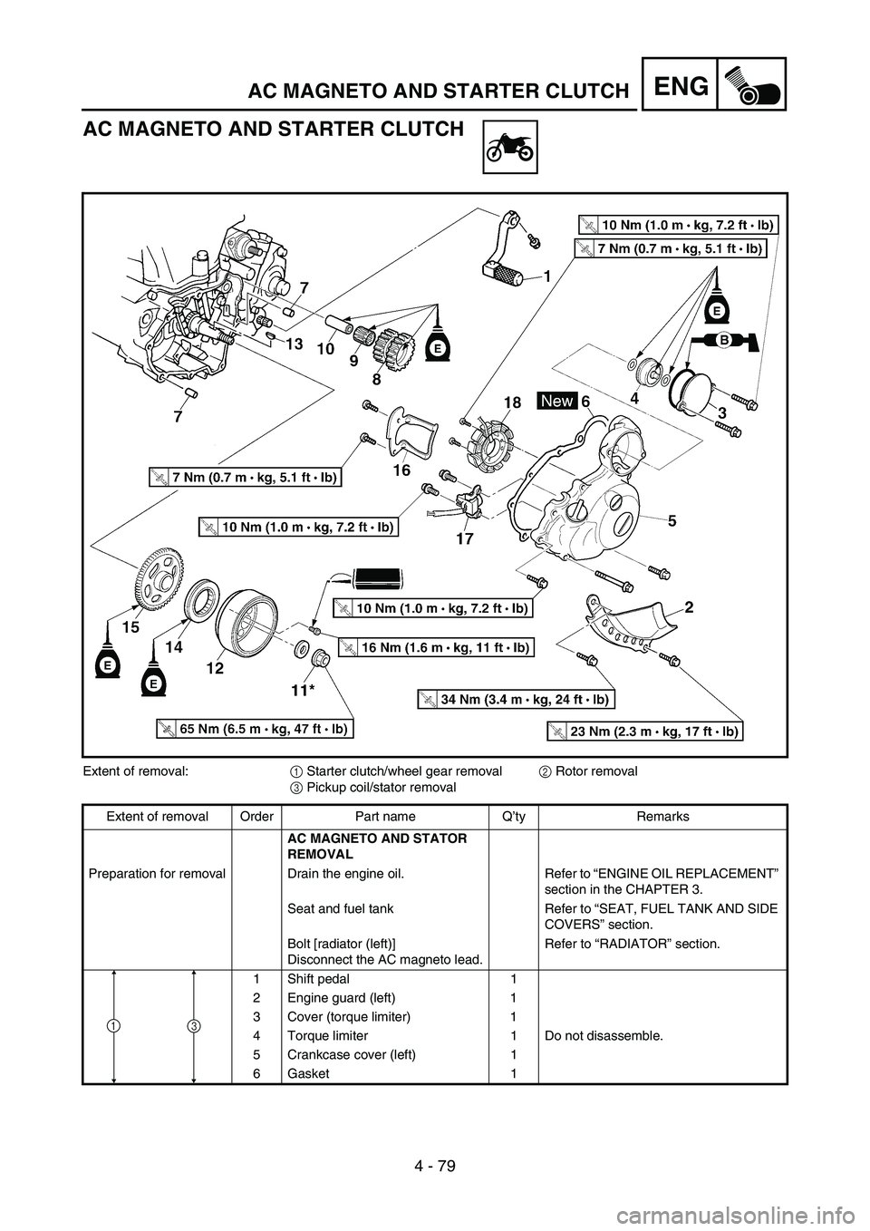
AC MAGNETO AND STARTER CLUTCH
Extent of removal:
1 Starter clutch/wheel gear removal
2 Rotor removal
3 Pickup coil/stator removal
Extent of removal Order Part name Q’ty Remarks
AC MAGNETO AND STATOR
REMOVAL
Preparation for removal Drain the engine oil. Refer to “ENGINE OIL REPLACEMENT”
section in the CHAPTER 3.
Seat and fuel tank Refer to “SEAT, FUEL TANK AND SIDE
COVERS” section.
Bolt [radiator (left)]
Disconnect the AC magneto lead.Refer to “RADIATOR” section.
1 Shift pedal 1
2 Engine guard (left) 1
3 Cover (torque limiter) 1
4 Torque limiter 1 Do not disassemble.
5 Crankcase cover (left) 1
6 Gasket 1
13
Page 524 of 786
4 - 104
ENGTRANSMISSION, SHIFT CAM AND SHIFT FORK
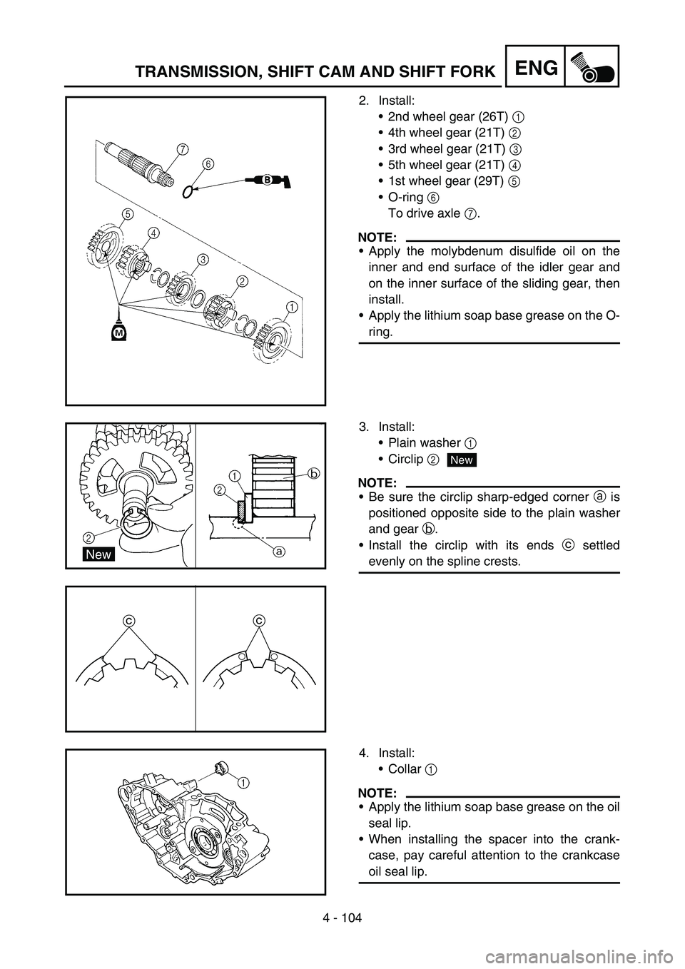
2. Install:
2nd wheel gear (26T) 1
4th wheel gear (21T) 2
3rd wheel gear (21T) 3
5th wheel gear (21T) 4
1st wheel gear (29T) 5
O-ring 6
To drive axle 7.
NOTE:
Apply the molybdenum disulfide oil on the
inner and end surface of the idler gear and
on the inner surface of the sliding gear, then
install.
Apply the lithium soap base grease on the O-
ring.
3. Install:
Plain washer 1
Circlip 2
NOTE:
Be sure the circlip sharp-edged corner a is
positioned opposite side to the plain washer
and gear b.
Install the circlip with its ends c settled
evenly on the spline crests.
cc
New
4. Install:
Collar 1
NOTE:
Apply the lithium soap base grease on the oil
seal lip.
When installing the spacer into the crank-
case, pay careful attention to the crankcase
oil seal lip.
Page 526 of 786
4 - 105
ENGTRANSMISSION, SHIFT CAM AND SHIFT FORK
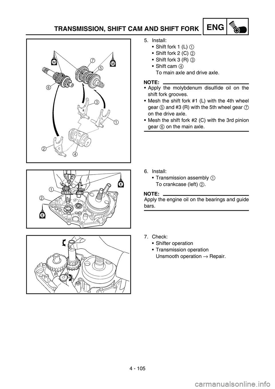
5. Install:
Shift fork 1 (L) 1
Shift fork 2 (C) 2
Shift fork 3 (R) 3
Shift cam 4
To main axle and drive axle.
NOTE:
Apply the molybdenum disulfide oil on the
shift fork grooves.
Mesh the shift fork #1 (L) with the 4th wheel
gear 5 and #3 (R) with the 5th wheel gear 7
on the drive axle.
Mesh the shift fork #2 (C) with the 3rd pinion
gear 6 on the main axle.
6. Install:
Transmission assembly 1
To crankcase (left) 2.
NOTE:
Apply the engine oil on the bearings and guide
bars.
7. Check:
Shifter operation
Transmission operation
Unsmooth operation → Repair.
Page 528 of 786
5 - 1
CHAS
EC500000
CHASSIS
EC590000
FRONT WHEEL AND REAR WHEEL
EC598000
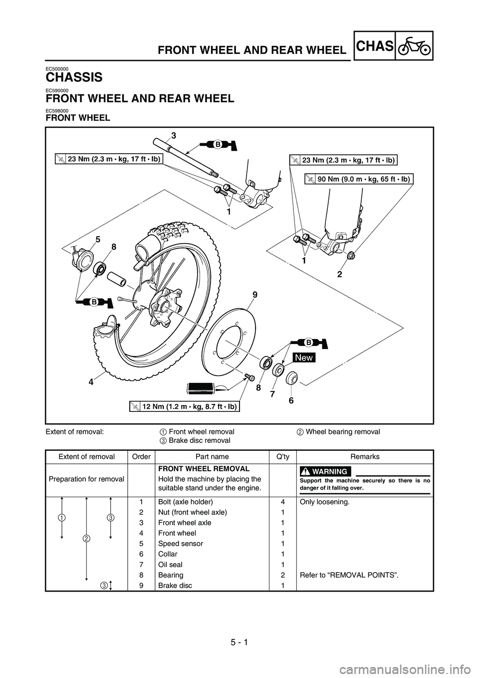
FRONT WHEEL
FRONT WHEEL AND REAR WHEEL
Extent of removal:
1 Front wheel removal
2 Wheel bearing removal
3 Brake disc removal
Extent of removal Order Part name Q’ty Remarks
FRONT WHEEL REMOVAL
WARNING
Support the machine securely so there is nodanger of it falling over.
Preparation for removal Hold the machine by placing the
suitable stand under the engine.
1 Bolt (axle holder) 4 Only loosening.
2 Nut (front wheel axle) 1
3 Front wheel axle 1
4 Front wheel 1
5 Speed sensor 1
6 Collar 1
7 Oil seal 1
8 Bearing 2 Refer to “REMOVAL POINTS”.
9 Brake disc 1
2
13
3
Page 530 of 786
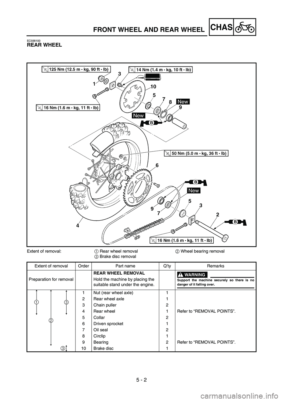
5 - 2
CHAS
EC598100
REAR WHEEL
Extent of removal:
1 Rear wheel removal
2 Wheel bearing removal
3 Brake disc removal
Extent of removal Order Part name Q’ty Remarks
REAR WHEEL REMOVAL
WARNING
Support the machine securely so there is nodanger of it falling over.
Preparation for removal Hold the machine by placing the
suitable stand under the engine.
1 Nut (rear wheel axle) 1
2 Rear wheel axle 1
3 Chain puller 2
4 Rear wheel 1 Refer to “REMOVAL POINTS”.
5 Collar 2
6 Driven sprocket 1
7 Oil seal 2
8 Circlip 1
9 Bearing 2 Refer to “REMOVAL POINTS”.
10 Brake disc 1
3
3
1
2
FRONT WHEEL AND REAR WHEEL