display YAMAHA WR 450F 2006 Notices Demploi (in French)
[x] Cancel search | Manufacturer: YAMAHA, Model Year: 2006, Model line: WR 450F, Model: YAMAHA WR 450F 2006Pages: 786, PDF Size: 22.49 MB
Page 67 of 786

GEN
INFO
2. Den Timer durch Drücken der
Taste “RST” starten.
3. Beim Stoppen des Timers müs-
sen die Tasten “SLCT1” und
“SLCT2” gleichzeitig gedrückt
werden.
HINWEIS:
Eine bei gestopptem Timer zurück-
gelegte Strecke wird nicht vom
Tageskilometerzähler A (TRIP A)
registriert.
4. Um die Messung wieder aufzu-
nehmen, die Tasten “SLCT1”
und “SLCT2” gleichzeitig drü-
cken.
Automatischer Start
1. Sicherstellen, dass das Display
sich in der RENNSPORT-
BETRIEBSART befindet. (Siehe
dazu “Von NORMAL- auf RENN-
SPORT-BETRIEBSART wech-
seln”.)
2. Die Maschine für ein Rennen
vorbereiten, indem die Taste
“SLCT1” mindestens 2 Sekun-
den lang gedrückt wird.
HINWEIS:
Wenn der Timer zu automatischem
Start bereit steht, blinken
und . Die Timer-Anzeige läuft von
links nach rechts ab.
3. Anfahren und den Timer starten.
4. Um den Timer zu stoppen, die
Tasten “SLCT1” und “SLCT2”
gleichzeitig drücken.
HINWEIS:
Eine bei gestopptem Timer zurück-
gelegte Strecke wird nicht vom
Tageskilometerzähler A (TRIP A)
registriert.
5. Um die Messung wieder aufzu-
nehmen, die Tasten “SLCT1”
und “SLCT2” gleichzeitig drü-
cken.
2. Lancer la mesure du chronomètre
en appuyant sur le bouton “RST”.
3. Pour arrêter la mesure du chrono-
mètre, appuyer sur les boutons
“SLCT1” et “SLCT2” en même
temps.
N.B.:
Si le véhicule continue à rouler lorsque
la mesure est désactivée, le chiffre du
totalisateur journalier A (TRIP A) n’est
pas modifié.
4. Pour reprendre la mesure, appuyer
de nouveau sur les boutons
“SLCT1” et “SLCT2” en même
temps.
Démarrage automatique
1. Vérifier que le passage en MODE
COURSE a bien été effectué. Se
reporter à la section “Passage du
MODE DE BASE en MODE
COURSE”.
2. Préparer le véhicule pour la course
en appuyant sur le bouton “SLCT1”
pendant 2 secondes minimum.
N.B.:
Lorsque le dispositif de mesure est prêt
pour la course avec démarrage automati-
que, et commencent à cligno-
ter. L’écran du chronomètre s’active et
défile de gauche à droite.
3. Démarrer le véhicule pour commen-
cer la mesure.
4. Pour arrêter la mesure du chrono-
mètre, appuyer sur les boutons
“SLCT1” et “SLCT2” en même
temps.
N.B.:
Si le véhicule continue à rouler lorsque
la mesure est désactivée, le chiffre du
totalisateur journalier A (TRIP A) n’est
pas modifié.
5. Pour reprendre la mesure, appuyer
de nouveau sur les boutons
“SLCT1” et “SLCT2” en même
temps.
2. Ponga en marcha el cronómetro pul-
sando el botón “RST”.
3. Para parar el cronómetro, pulse el
botón “SLCT1” y el botón
“SLCT2” al mismo tiempo.
NOTA:
Si la máquina avanza con el cronómetro
parado, las cifras del cuentakilómetros
parcial A (TRIP A) no cambian.
4. Para volver a poner en marcha el
cronómetro, pulse el botón
“SLCT1” y el botón “SLCT2” al
mismo tiempo.
Puesta en marcha automática
1. Compruebe que haya cambiado a
FUNCIÓN COMPETICIÓN. (Con-
sulte el apartado “Cambio de FUN-
CIÓN BÁSICA a FUNCIÓN
COMPETICIÓN”.)
2. Prepare el cronómetro para un reco-
rrido pulsando el botón “SLCT1”
durante 2 segundos o más.
NOTA:
Cuando el cronómetro está preparado
para un recorrido con puesta en marcha
automática, y comienzan a par-
padear. La indicación del cronómetro se
activa y se desplaza de izquierda a dere-
cha.
3. El cronómetro se pone en marcha
cuando la máquina comienza a
moverse.
4. Para parar el cronómetro, pulse el
botón “SLCT1” y el botón
“SLCT2” al mismo tiempo.
NOTA:
Si la máquina avanza con el cronómetro
parado, las cifras del cuentakilómetros
parcial A (TRIP A) no cambian.
5. Para volver a poner en marcha el
cronómetro, pulse el botón
“SLCT1” y el botón “SLCT2” al
mismo tiempo.
ECRAN MULTIFONCTION
MULTIFUNKTIONSANZEIGE
VISOR MULTIFUNCIÓN
1 - 18
Page 68 of 786

1 - 19
GEN
INFO
MULTI-FUNCTION DISPLAY
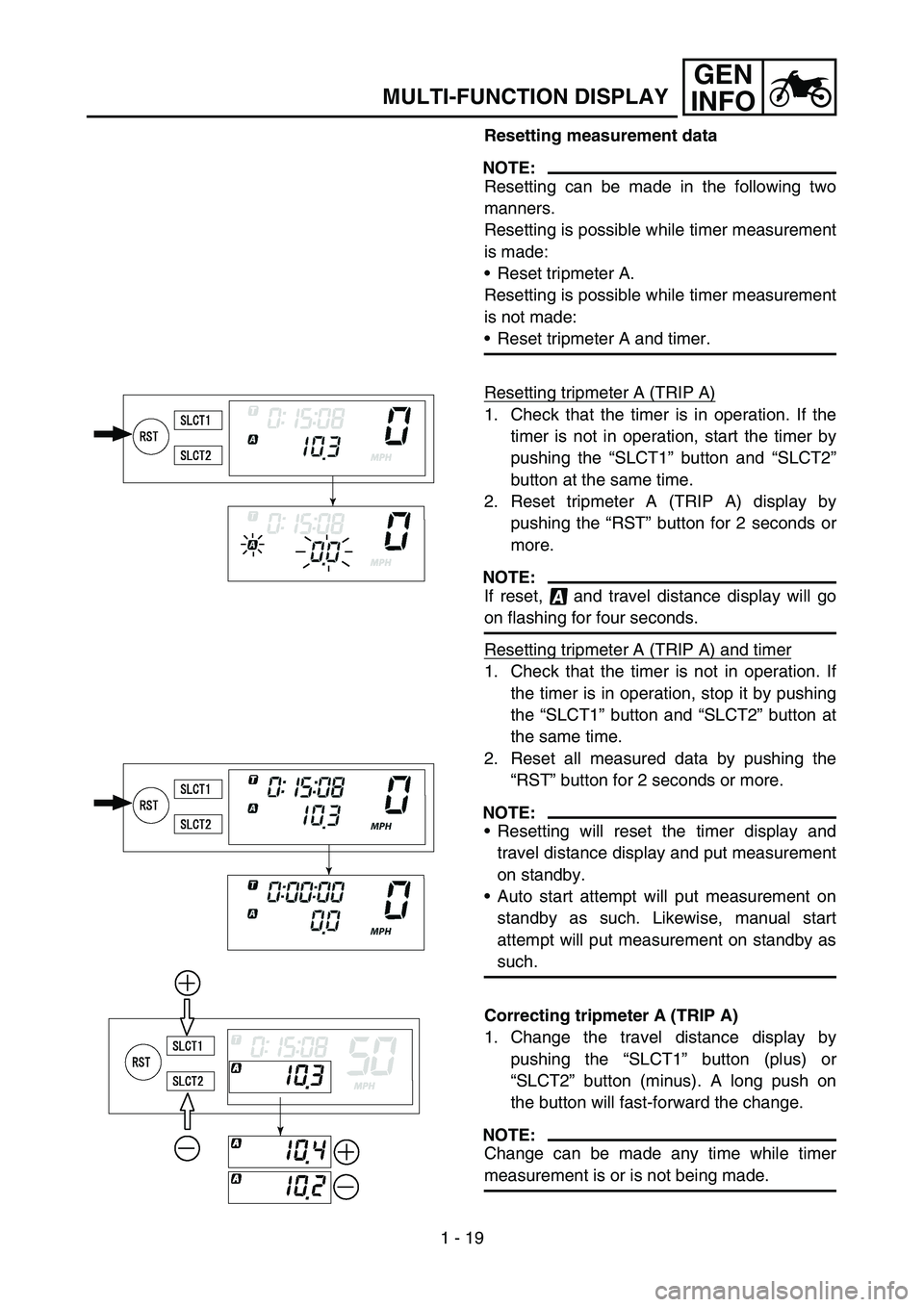
Resetting measurement data
NOTE:
Resetting can be made in the following two
manners.
Resetting is possible while timer measurement
is made:
Reset tripmeter A.
Resetting is possible while timer measurement
is not made:
Reset tripmeter A and timer.
Resetting tripmeter A (TRIP A)
1. Check that the timer is in operation. If the
timer is not in operation, start the timer by
pushing the “SLCT1” button and “SLCT2”
button at the same time.
2. Reset tripmeter A (TRIP A) display by
pushing the “RST” button for 2 seconds or
more.
NOTE:
If reset, and travel distance display will go
on flashing for four seconds.
Resetting tripmeter A (TRIP A) and timer
1. Check that the timer is not in operation. If
the timer is in operation, stop it by pushing
the “SLCT1” button and “SLCT2” button at
the same time.
2. Reset all measured data by pushing the
“RST” button for 2 seconds or more.
NOTE:
Resetting will reset the timer display and
travel distance display and put measurement
on standby.
Auto start attempt will put measurement on
standby as such. Likewise, manual start
attempt will put measurement on standby as
such.
Correcting tripmeter A (TRIP A)
1. Change the travel distance display by
pushing the “SLCT1” button (plus) or
“SLCT2” button (minus). A long push on
the button will fast-forward the change.
NOTE:
Change can be made any time while timer
measurement is or is not being made.
Page 70 of 786

GEN
INFO
1 - 20
MULTI-FUNCTION DISPLAY
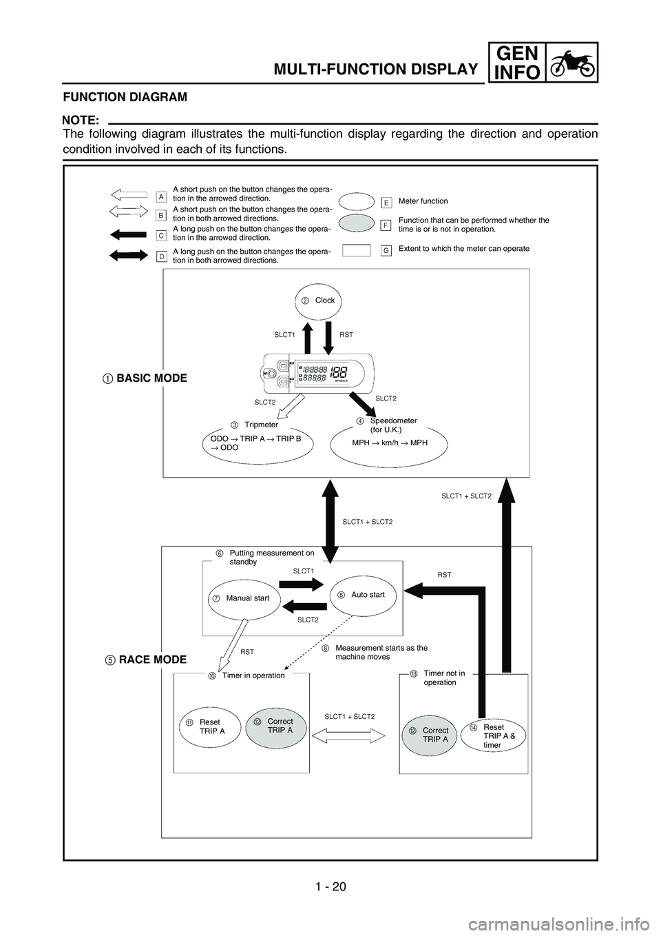
FUNCTION DIAGRAM
NOTE:
The following diagram illustrates the multi-function display regarding the direction and operation
condition involved in each of its functions.
A short push on the button changes the opera-
tion in the arrowed direction.
A short push on the button changes the opera-
tion in both arrowed directions.
A long push on the button changes the opera-
tion in the arrowed direction.
A long push on the button changes the opera-
tion in both arrowed directions.Meter function
Function that can be performed whether the
time is or is not in operation.
Extent to which the meter can operate
2Clock
3Tripmeter4Speedometer
(for U.K.)
ODO
→ TRIP A
→ TRIP B
→ ODOMPH
→ km/h
→ MPH
6Putting measurement on
standby
7Manual start8Auto start
9Measurement starts as the
machine moves
0Timer in operation
AReset
TRIP ABCorrect
TRIP ACTimer not in
operation
BCorrect
TRIP ADReset
TRIP A &
timer
1BASIC MODE
5RACE MODE
Page 105 of 786

SPEC
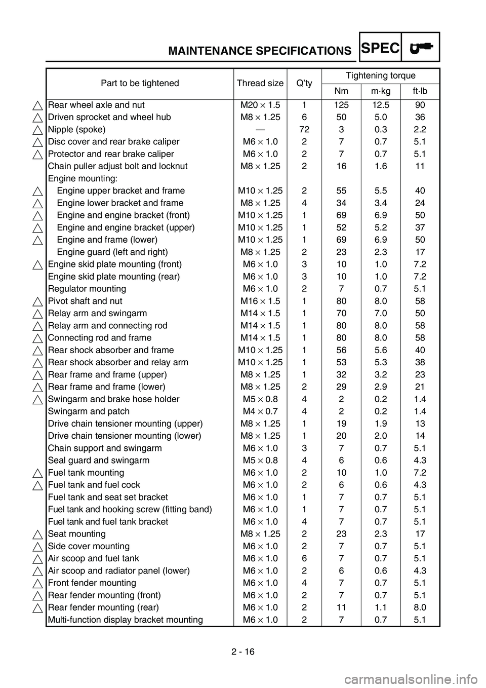
2 - 16 Part to be tightened Thread size Q’tyTightening torque
Nm m·kg ft·lb
Rear wheel axle and nut M20 × 1.5 1 125 12.5 90
Driven sprocket and wheel hub M8 × 1.25 6 50 5.0 36
Nipple (spoke)—72 3 0.3 2.2
Disc cover and rear brake caliper M6 × 1.0 2 7 0.7 5.1
Protector and rear brake caliper M6 × 1.0 2 7 0.7 5.1
Chain puller adjust bolt and locknut M8 × 1.25 2 16 1.6 11
Engine mounting:
Engine upper bracket and frame M10 × 1.25 2 55 5.5 40
Engine lower bracket and frame M8 × 1.25 4 34 3.4 24
Engine and engine bracket (front) M10 × 1.25 1 69 6.9 50
Engine and engine bracket (upper) M10 × 1.25 1 52 5.2 37
Engine and frame (lower) M10 × 1.25 1 69 6.9 50
Engine guard (left and right) M8 × 1.25 2 23 2.3 17
Engine skid plate mounting (front) M6 × 1.0 3 10 1.0 7.2
Engine skid plate mounting (rear) M6 × 1.0 3 10 1.0 7.2
Regulator mounting M6 × 1.0 2 7 0.7 5.1
Pivot shaft and nut M16 × 1.5 1 80 8.0 58
Relay arm and swingarm M14 × 1.5 1 70 7.0 50
Relay arm and connecting rod M14 × 1.5 1 80 8.0 58
Connecting rod and frame M14 × 1.5 1 80 8.0 58
Rear shock absorber and frame M10 × 1.25 1 56 5.6 40
Rear shock absorber and relay arm M10 × 1.25 1 53 5.3 38
Rear frame and frame (upper) M8 × 1.25 1 32 3.2 23
Rear frame and frame (lower) M8 × 1.25 2 29 2.9 21
Swingarm and brake hose holder M5 × 0.8 4 2 0.2 1.4
Swingarm and patch M4 × 0.7 4 2 0.2 1.4
Drive chain tensioner mounting (upper) M8 × 1.25 1 19 1.9 13
Drive chain tensioner mounting (lower) M8 × 1.25 1 20 2.0 14
Chain support and swingarm M6 × 1.0 3 7 0.7 5.1
Seal guard and swingarm M5 × 0.8 4 6 0.6 4.3
Fuel tank mounting M6 × 1.0 2 10 1.0 7.2
Fuel tank and fuel cock M6 × 1.0 2 6 0.6 4.3
Fuel tank and seat set bracket M6 × 1.0 1 7 0.7 5.1
Fuel tank and hooking screw (fitting band) M6 × 1.0 1 7 0.7 5.1
Fuel tank and fuel tank bracket M6 × 1.0 4 7 0.7 5.1
Seat mounting M8 × 1.25 2 23 2.3 17
Side cover mounting M6 × 1.0 2 7 0.7 5.1
Air scoop and fuel tank M6 × 1.0 6 7 0.7 5.1
Air scoop and radiator panel (lower) M6 × 1.0 2 6 0.6 4.3
Front fender mounting M6 × 1.0 4 7 0.7 5.1
Rear fender mounting (front) M6 × 1.0 2 7 0.7 5.1
Rear fender mounting (rear) M6 × 1.0 2 11 1.1 8.0
Multi-function display bracket mounting M6 × 1.0 2 7 0.7 5.1
MAINTENANCE SPECIFICATIONS
Page 106 of 786

SPEC
2 - 17
NOTE:
- marked portion shall be checked for torque tightening after break-in or before each race. Multi-function display mounting M5 × 0.8 2 4 0.4 2.9
Plate 1 and protector M5 × 0.8 2 4 0.4 2.9
Plate 2 and protector—2 0.5 0.05 0.36
Speed sensor lead holder and headlight stay
(lower)M6 × 1.0 1 7 0.7 5.1
Headlight stay (lower) and under bracket M8 × 1.25 2 15 1.5 11
Headlight body and headlight unit M6 × 1.0 2 7 0.7 5.1
Headlight mounting (left and right) M6 × 1.0 2 7 0.7 5.1
Headlight mounting (lower) M6 × 1.0 1 7 0.7 5.1
Taillight mounting M6 × 1.0 3 4 0.4 2.9
Taillight lead clamp and rear fender—2 0.5 0.05 0.36
Coolant reservoir tank mounting M6 × 1.0 2 7 0.7 5.1
Sidestand bracket mounting M10 × 1.25 2 66 6.6 48
Drive chain stopper and sidestand bracket M6 × 1.0 1 7 0.7 5.1
Sidestand mounting M8 × 1.25 1 20 2.0 14 Part to be tightened Thread size Q’tyTightening torque
Nm m·kg ft·lb
MAINTENANCE SPECIFICATIONS
Page 184 of 786

2 - 28
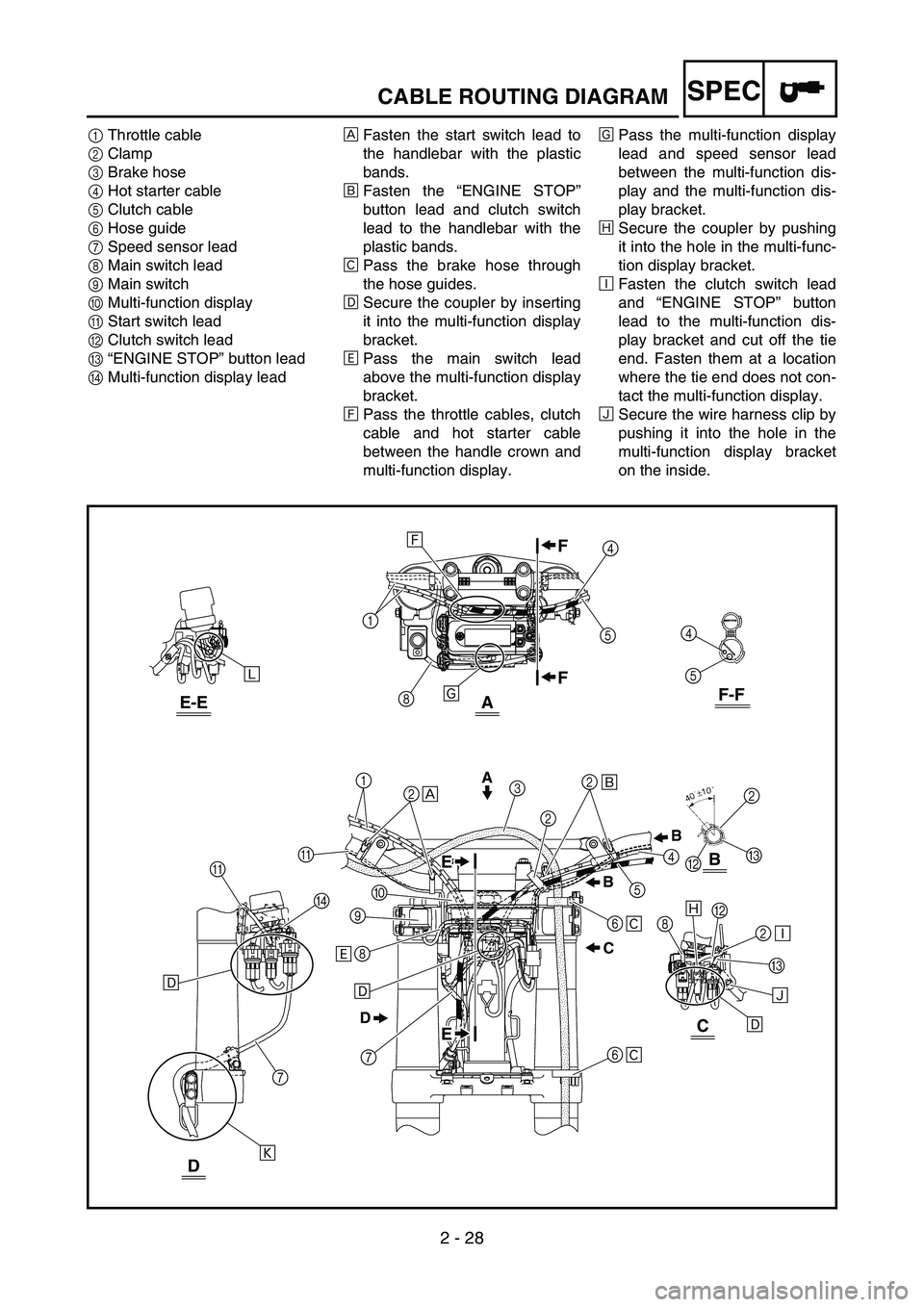
SPECCABLE ROUTING DIAGRAM
1Throttle cable
2Clamp
3Brake hose
4Hot starter cable
5Clutch cable
6Hose guide
7Speed sensor lead
8Main switch lead
9Main switch
0Multi-function display
AStart switch lead
BClutch switch lead
C“ENGINE STOP” button lead
DMulti-function display leadÈFasten the start switch lead to
the handlebar with the plastic
bands.
ÉFasten the “ENGINE STOP”
button lead and clutch switch
lead to the handlebar with the
plastic bands.
ÊPass the brake hose through
the hose guides.
ËSecure the coupler by inserting
it into the multi-function display
bracket.
ÌPass the main switch lead
above the multi-function display
bracket.
ÍPass the throttle cables, clutch
cable and hot starter cable
between the handle crown and
multi-function display.ÎPass the multi-function display
lead and speed sensor lead
between the multi-function dis-
play and the multi-function dis-
play bracket.
ÏSecure the coupler by pushing
it into the hole in the multi-func-
tion display bracket.
ÐFasten the clutch switch lead
and “ENGINE STOP” button
lead to the multi-function dis-
play bracket and cut off the tie
end. Fasten them at a location
where the tie end does not con-
tact the multi-function display.
ÑSecure the wire harness clip by
pushing it into the hole in the
multi-function display bracket
on the inside.
4
5
Î
Ê Ó
A
B
F-FE-E
C
D
A
D
7
7
Ò ËA
12
È32
É
6
Ê
6
8
Ì0
9
ËÑ C
BÏ
2
Ð 8
8
1Í
4
5
4
5B2
C
DC BB A
F F
EE
EE
Ë
2
Page 186 of 786

2 - 29
SPECCABLE ROUTING DIAGRAM
ÒPass the speed sensor lead
through the guide on the out-
side of the front fork.
ÓPass the start switch lead and
multi-function display lead (on
the wire harness side) above
the multi-function display lead
(on the side of the multi-func-
tion display lead) and speed
sensor lead, and then to the
right of the chassis.
4
5
Î
Ê Ó
A
B
F-FE-E
C
D
A
D
7
7
Ò ËA
12
È32
É
6
Ê
6
8
Ì0
9
ËÑ C
BÏ
2
Ð 8
8
1Í
4
5
4
5B2
C
DC BB A
F F
EE
EE
Ë
2
Page 666 of 786

6 - 1
–+ELECELECTRICAL COMPONENTS AND WIRING DIAGRAM
EC600000
ELECTRICAL
EC610000
ELECTRICAL COMPONENTS AND WIRING DIAGRAM
EC611000
ELECTRICAL COMPONENTS
1Headlight
2Multi-function display
3“ENGINE STOP” but-
ton
4Clutch switch
5Diode
6Starter relay diode
7TPS (throttle posi-
tion sensor)
8Starter relay
9Fuse
0Starting circuit cut-off
relayATaillight
BNeutral switch
CStarter motor
DAC magneto
ERectifier/regulator
FIgnition coil
GSpark plug
HStart switch
IMain switch
JCDI unit
KSpeed sensor
LBatteryCOLOR CODE
B ...................... Black
Br ..................... Brown
Ch .................... Chocolate
Dg .................... Dark green
Gy .................... Gray
L....................... Blue
O ...................... Orange
R ...................... Red
Sb .................... Sky blue
W ..................... White
EC612000
WIRING DIAGRAM
FGH
I
J
K
L
1 234
56
789
0A
B C
D E
B/L
W
W
R
BR/BBr
R
BR/BBr
R
Y
Y
L/R/BBB
SbL/W
L/YBBB
WY
RY
R
LY
B
YLB/L
B
B
ON
OFF
10A
BB
OFF
START
R-BrL/W
B
BrL/W
BrL/W
L/B
-Y
Y
B
LY
B
L/WSb
B/WBBB
W/R/W
R/
BGyBrL/W
ON
STOP
O
LSbB/L
W RBrB/W
L
/
BGyWR
/B
B O
L/YSbL/R
R W
Y W
Y W
Y
L B
B
B
RRR/B
B Br B
B B B B
L/W
R
R
R R B
R
BrBr
L/W L/
W
Br B
L/B
L/B
L/R
Br
R/B
L/B L
/W
B/W
WW
/RW
RO
L
Y
ELO
B
L
Y
B/LSb*1
Sb
*2B/W
B
B
L/R L/Y L/Y
B
SbSbL/W
B
Gy
SbBB/LYO
L
*2
O B
L YL/W
B/L
*1
D
E
CI
6
H4 5
B3J
K
2FG
7
8L9
1A
*2
*1
W
B
R/W
Ch
Dg
Y
B BrRW
WRB/W
SIGNAL
+
Backup
SLCT1
SLCT2
RST
GND
BrR/WB
B
R/WBr
WRB/W
R B
W
ChDgYB
B/WWRB/WWR
0
R
W
W W
L/WB/L
Y B
RB
B
L
L
*1: For USA
*2: Except for USA
Y ...................... Yellow
B/L ................... Black/Blue
B/W .................. Black/White
L/B ................... Blue/Black
L/R ................... Blue/Red
L/Y ................... Blue/Yellow
L/W .................. Blue/White
R/B................... Red/Black
R/W.................. Red/White
Page 728 of 786

–+ELEC
6 - 26
SIGNALING SYSTEM
SIGNALING SYSTEM
INSPECTION STEPS
If the speedometer will not operate, use the following inspection steps.
*1 marked: Refer to “BATTERY INSPECTION AND CHARGING” section in the CHAPTER 3.
NOTE:
•Remove the following parts before inspection.
1) Headlight
•Use the following special tools in this inspection.
Pocket tester:
YU-3112-C/90890-03112
*1 Check battery. Recharge or replace.
Check each coupler and
wire connection.Repair or replace.
Check multi-function dis-
play.Input voltage Replace wire harness.
Output voltageReplace multi-func-
tion display.
Check speed sensor. Replace.
OK
OK
OK
No good
No good
No good No good
No good
Page 732 of 786

6 - 27
–+ELECSIGNALING SYSTEM
COUPLERS AND LEADS CONNECTION
INSPECTION
1. Check:
•Couplers and leads connection
Rust/dust/looseness/short-circuit →
Repair or replace.
MULTI-FUNCTION DISPLAY INPUT
VOLTAGE INSPECTION
1. Disconnect the multi-function display cou-
pler.
2. Set the main switch to “ON”.
3. Measure:
•Multi-function display input voltage
Out of specification → Replace wire har-
ness.
CAUTION:
Make sure that a short-circuit does not
develop between the terminals because it
may cause damage to electrical compo-
nents.Tester (+) lead
→ Brown lead
1
Tester (–) lead
→ Black lead
2
Multi-function dis-
play input voltageTester selec-
tor position
10 V or more DCV-20
MULTI-FUNCTION DISPLAY OUTPUT
VOLTAGE INSPECTION
1. Disconnect the multi-function display cou-
pler.
2. Set the main switch to “ON”.