oil level YAMAHA WR 450F 2008 User Guide
[x] Cancel search | Manufacturer: YAMAHA, Model Year: 2008, Model line: WR 450F, Model: YAMAHA WR 450F 2008Pages: 224, PDF Size: 13.7 MB
Page 92 of 224

4-5
CHASSIS
CHASSIS
SELECTION OF THE SECONDARY
REDUCTION RATIO (SPROCKET)
• It is generally said that the second-
ary gear ratio should be reduced for
a longer straight portion of a speed
course and should be increased for
a course with many corners. Actual-
ly, however, as the speed depends
on the ground condition of the day
of the race, be sure to run through
the circuit to set the machine suit-
able for the entire course.
• In actuality, it is very difficult to
achieve settings suitable for the en-
tire course and some settings may
be sacrificed. Thus, the settings
should be matched to the portion of
the course that has the greatest ef-
fect on the race result. In such a
case, run through the entire course
while making notes of lap times to
find the best balance; then, deter-
mine the secondary reduction ratio.
• If a course has a long straight por-
tion where a machine can run at
maximum speed, the machine is
generally set such that it can devel-
op its maximum revolutions toward
the end of the straight line, with care
taken to avoid the engine over-rev-
ving.
Riding technique varies from rider to
rider and the performance of a ma-
chine also vary from machine to ma-
chine. Therefore, do not imitate other
rider's settings from the beginning but
choose your own setting according to
the level of your riding technique.
DRIVE AND REAR WHEEL
SPROCKETS SETTING PARTS
TIRE PRESSURE
Tire pressure should be adjust to suit
the road surface condition of the cir-
cuit.• Under a rainy, muddy, sandy, or
slippery condition, the tire pressure
should be lower for a larger area of
contact with the road surface.
• Under a stony or hard road condi-
tion, the tire pressure should be
higher to prevent a flat tire.
FRONT FORK SETTING
The front fork setting should be made
depending on the rider's feeling of an
actual run and the circuit conditions.
The front fork setting includes the fol-
lowing three factors:
1. Setting of air spring characteris-
tics
• Change the fork oil level.
2. Setting of spring preload
• Change the spring.
• Install the adjustment washer.
3. Setting of damping force
• Change the compression damp-
ing.
• Change the rebound damping.
The spring acts on the load and
the damping force acts on the
cushion travel speed.
CHANGE IN LEVEL AND
CHARACTERISTICS OF FORK OIL
Damping characteristic near the final
stroke can be changed by changing
the fork oil amount.
Adjust the oil level in 5 mm (0.2 in)
increments or decrements. Too
low oil level causes the front fork
to produce a noise at full rebound
or the rider to feel some pressure
on his hands or body. Alternative-
ly, too high oil level will develop
unexpectedly early oil lock with
the consequent shorter front fork
travel and deteriorated perfor-
mance and characteristics. There-
fore, adjust the front fork within
the specified range.
Secondary reduction ratio =
Number of rear wheel sprocket
teeth/Number of drive sprocket
teeth
Standard secondary
reduction ratio50/13
(3.846)
* 47/14
(3.357)
* For EUROPE
Part
nameSize Part number
Drive
sprocket
"1"
(STD) 13T 9383E-13233
* 14T 9383E-14215
** (STD) ** 14T 5NG-17460-00
* For AUS and NZ
** For EUROPE
Part
nameSize Part number
Rear
wheel
sprocket
"2"
** (STD) ** 47T 1C3-25447-00
48T 5GS-25448-50
* 48T 1C3-25448-00
* 49T 1C3-25449-00
(STD) 50T 5TJ-25450-80
* (STD) * 50T 1C3-25450-00
* 51T 1C3-25451-00
52T 5TJ-25452-80
* 52T 1C3-25452-00
* For AUS and NZ
** For EUROPE
Standard tire pressure:
100 kPa (1.0 kgf/cm
2,
15 psi)
Extent of adjustment:
60–80 kPa (0.6–0.8 kgf/
cm
2, 9.0–12 psi)
Extent of adjustment:
100–120 kPa (1.0–1.2
kgf/cm
2, 15–18 psi)
Page 93 of 224
4-6
CHASSIS
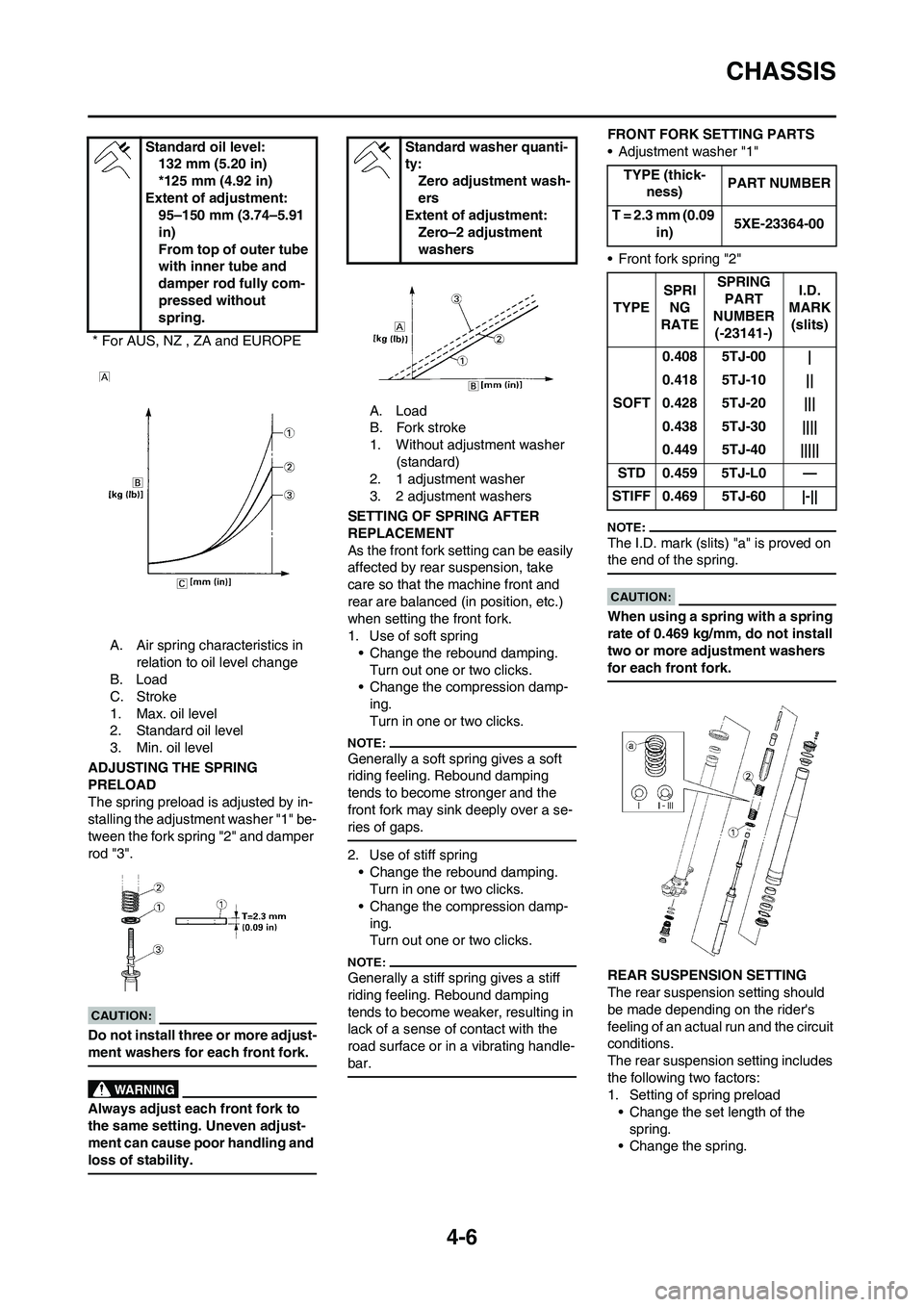
A. Air spring characteristics in
relation to oil level change
B. Load
C. Stroke
1. Max. oil level
2. Standard oil level
3. Min. oil level
ADJUSTING THE SPRING
PRELOAD
The spring preload is adjusted by in-
stalling the adjustment washer "1" be-
tween the fork spring "2" and damper
rod "3".
Do not install three or more adjust-
ment washers for each front fork.
Always adjust each front fork to
the same setting. Uneven adjust-
ment can cause poor handling and
loss of stability.
A. Load
B. Fork stroke
1. Without adjustment washer
(standard)
2. 1 adjustment washer
3. 2 adjustment washers
SETTING OF SPRING AFTER
REPLACEMENT
As the front fork setting can be easily
affected by rear suspension, take
care so that the machine front and
rear are balanced (in position, etc.)
when setting the front fork.
1. Use of soft spring
• Change the rebound damping.
Turn out one or two clicks.
• Change the compression damp-
ing.
Turn in one or two clicks.
Generally a soft spring gives a soft
riding feeling. Rebound damping
tends to become stronger and the
front fork may sink deeply over a se-
ries of gaps.
2. Use of stiff spring
• Change the rebound damping.
Turn in one or two clicks.
• Change the compression damp-
ing.
Turn out one or two clicks.
Generally a stiff spring gives a stiff
riding feeling. Rebound damping
tends to become weaker, resulting in
lack of a sense of contact with the
road surface or in a vibrating handle-
bar.
FRONT FORK SETTING PARTS
• Adjustment washer "1"
• Front fork spring "2"
The I.D. mark (slits) "a" is proved on
the end of the spring.
When using a spring with a spring
rate of 0.469 kg/mm, do not install
two or more adjustment washers
for each front fork.
REAR SUSPENSION SETTING
The rear suspension setting should
be made depending on the rider's
feeling of an actual run and the circuit
conditions.
The rear suspension setting includes
the following two factors:
1. Setting of spring preload
• Change the set length of the
spring.
• Change the spring. Standard oil level:
132 mm (5.20 in)
*125 mm (4.92 in)
Extent of adjustment:
95–150 mm (3.74–5.91
in)
From top of outer tube
with inner tube and
damper rod fully com-
pressed without
spring.
* For AUS, NZ , ZA and EUROPE
Standard washer quanti-
ty:
Zero adjustment wash-
ers
Extent of adjustment:
Zero–2 adjustment
washers
TYPE (thick-
ness)PART NUMBER
T = 2.3 mm (0.09
in)5XE-23364-00
TYPESPRI
NG
RATESPRING
PART
NUMBER
(-23141-)I.D.
MARK
(slits)
SOFT0.408 5TJ-00 |
0.418 5TJ-10 ||
0.428 5TJ-20 |||
0.438 5TJ-30 ||||
0.449 5TJ-40 |||||
STD 0.459 5TJ-L0 —
STIFF 0.469 5TJ-60 |-||
Page 95 of 224
4-8
CHASSIS
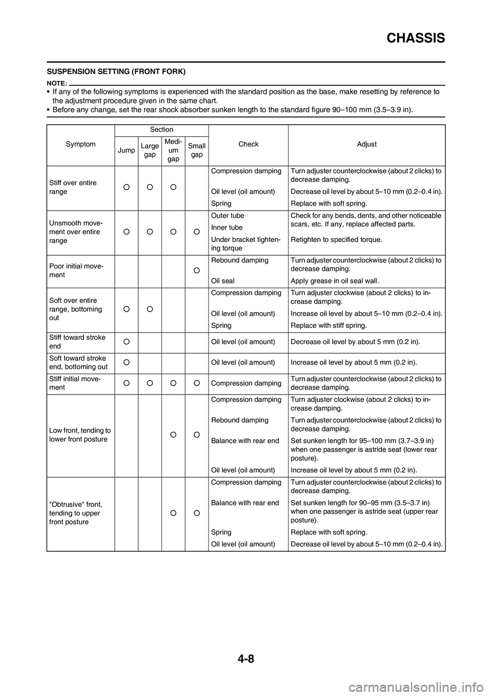
SUSPENSION SETTING (FRONT FORK)
• If any of the following symptoms is experienced with the standard position as the base, make resetting by reference to
the adjustment procedure given in the same chart.
• Before any change, set the rear shock absorber sunken length to the standard figure 90–100 mm (3.5–3.9 in).
SymptomSection
Check Adjust
JumpLarge
gapMedi-
um
gapSmall
gap
Stiff over entire
range○○○Compression damping Turn adjuster counterclockwise (about 2 clicks) to
decrease damping.
Oil level (oil amount) Decrease oil level by about 5–10 mm (0.2–0.4 in).
Spring Replace with soft spring.
Unsmooth move-
ment over entire
range○○○○Outer tube Check for any bends, dents, and other noticeable
scars, etc. If any, replace affected parts.
Inner tube
Under bracket tighten-
ing torqueRetighten to specified torque.
Poor initial move-
ment○Rebound damping Turn adjuster counterclockwise (about 2 clicks) to
decrease damping.
Oil seal Apply grease in oil seal wall.
Soft over entire
range, bottoming
out○○Compression damping Turn adjuster clockwise (about 2 clicks) to in-
crease damping.
Oil level (oil amount) Increase oil level by about 5–10 mm (0.2–0.4 in).
Spring Replace with stiff spring.
Stiff toward stroke
end○Oil level (oil amount) Decrease oil level by about 5 mm (0.2 in).
Soft toward stroke
end, bottoming out○Oil level (oil amount) Increase oil level by about 5 mm (0.2 in).
Stiff initial move-
ment○○○○Compression dampingTurn adjuster counterclockwise (about 2 clicks) to
decrease damping.
Low front, tending to
lower front posture○○Compression damping Turn adjuster clockwise (about 2 clicks) to in-
crease damping.
Rebound damping Turn adjuster counterclockwise (about 2 clicks) to
decrease damping.
Balance with rear end Set sunken length for 95–100 mm (3.7–3.9 in)
when one passenger is astride seat (lower rear
posture).
Oil level (oil amount) Increase oil level by about 5 mm (0.2 in).
"Obtrusive" front,
tending to upper
front posture○○Compression damping Turn adjuster counterclockwise (about 2 clicks) to
decrease damping.
Balance with rear end Set sunken length for 90–95 mm (3.5–3.7 in)
when one passenger is astride seat (upper rear
posture).
Spring Replace with soft spring.
Oil level (oil amount) Decrease oil level by about 5–10 mm (0.2–0.4 in).
Page 132 of 224
5-36
OIL FILTER ELEMENT AND WATER PUMP
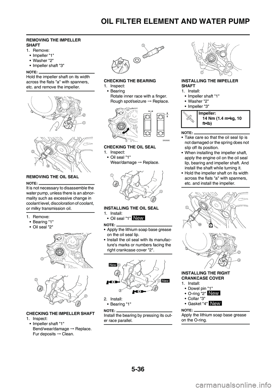
REMOVING THE IMPELLER
SHAFT
1. Remove:
• Impeller "1"
• Washer "2"
• Impeller shaft "3"
Hold the impeller shaft on its width
across the flats "a" with spanners,
etc. and remove the impeller.
REMOVING THE OIL SEAL
It is not necessary to disassemble the
water pump, unless there is an abnor-
mality such as excessive change in
coolant level, discoloration of coolant,
or milky transmission oil.
1. Remove:
• Bearing "1"
• Oil seal "2"
CHECKING THE IMPELLER SHAFT
1. Inspect:
• Impeller shaft "1"
Bend/wear/damage→Replace.
Fur deposits→Clean.CHECKING THE BEARING
1. Inspect:
•Bearing
Rotate inner race with a finger.
Rough spot/seizure→Replace.
CHECKING THE OIL SEAL
1. Inspect:
• Oil seal "1"
Wear/damage→Replace.
INSTALLING THE OIL SEAL
1. Install:
• Oil seal "1"
• Apply the lithium soap base grease
on the oil seal lip.
• Install the oil seal with its manufac-
ture's marks or numbers facing the
right crankcase cover "2".
2. Install:
•Bearing "1"
Install the bearing by pressing its out-
er race parallel.
INSTALLING THE IMPELLER
SHAFT
1. Install:
• Impeller shaft "1"
• Washer "2"
• Impeller "3"
• Take care so that the oil seal lip is
not damaged or the spring does not
slip off its position.
• When installing the impeller shaft,
apply the engine oil on the oil seal
lip, bearing and impeller shaft. And
install the shaft while turning it.
• Hold the impeller shaft on its width
across the flats "a" with spanners,
etc. and install the impeller.
INSTALLING THE RIGHT
CRANKCASE COVER
1. Install:
• Dowel pin "1"
• O-ring "2"
•Collar "3"
• Gasket "4"
Apply the lithium soap base grease
on the O-ring.
Impeller:
14 Nm (1.4 m•kg, 10
ft•lb)
Page 175 of 224
6-14
FRONT BRAKE AND REAR BRAKE
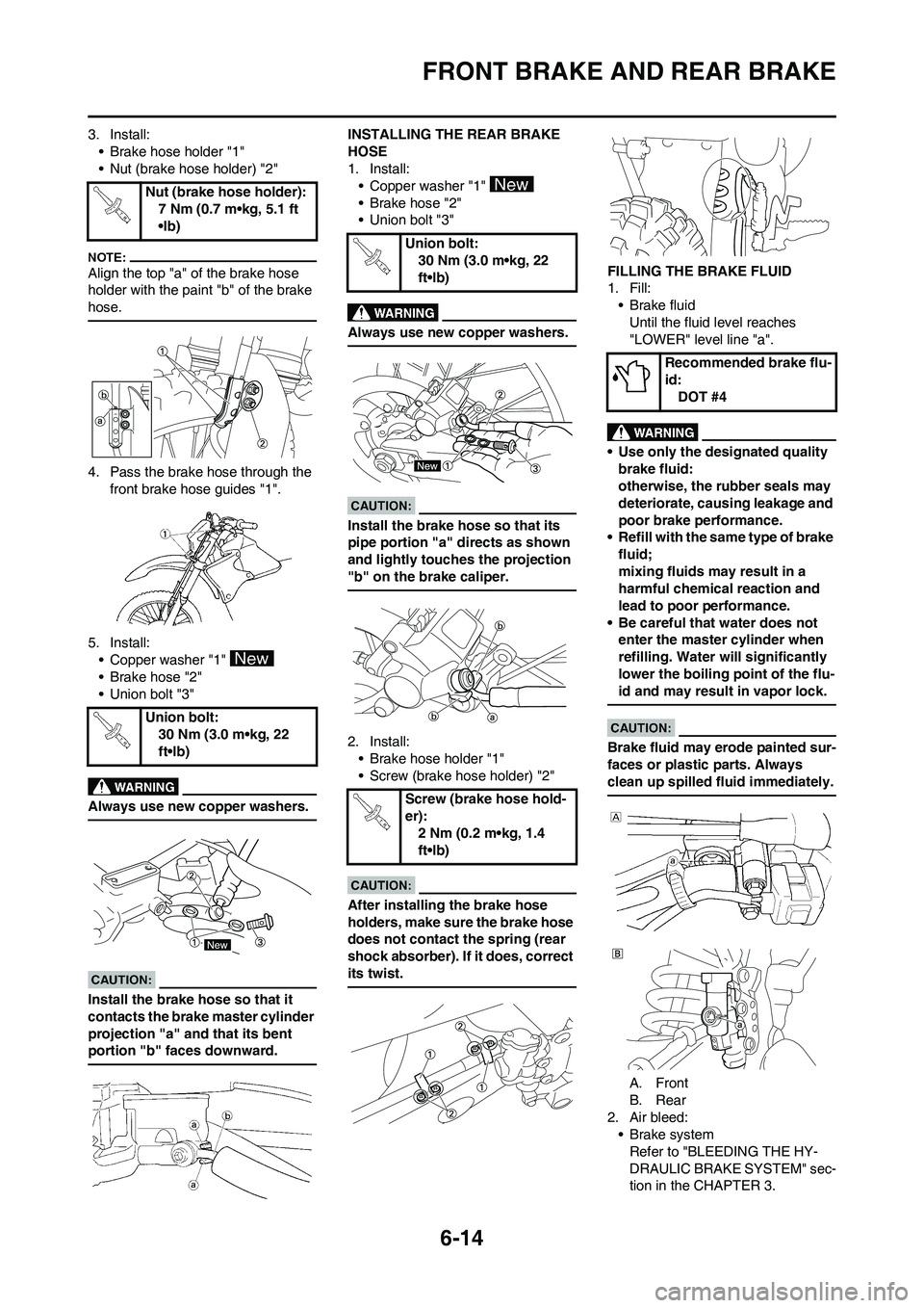
3. Install:
• Brake hose holder "1"
• Nut (brake hose holder) "2"
Align the top "a" of the brake hose
holder with the paint "b" of the brake
hose.
4. Pass the brake hose through the
front brake hose guides "1".
5. Install:
• Copper washer "1"
• Brake hose "2"
• Union bolt "3"
Always use new copper washers.
Install the brake hose so that it
contacts the brake master cylinder
projection "a" and that its bent
portion "b" faces downward.
INSTALLING THE REAR BRAKE
HOSE
1. Install:
• Copper washer "1"
• Brake hose "2"
• Union bolt "3"
Always use new copper washers.
Install the brake hose so that its
pipe portion "a" directs as shown
and lightly touches the projection
"b" on the brake caliper.
2. Install:
• Brake hose holder "1"
• Screw (brake hose holder) "2"
After installing the brake hose
holders, make sure the brake hose
does not contact the spring (rear
shock absorber). If it does, correct
its twist.
FILLING THE BRAKE FLUID
1. Fill:
• Brake fluid
Until the fluid level reaches
"LOWER" level line "a".
• Use only the designated quality
brake fluid:
otherwise, the rubber seals may
deteriorate, causing leakage and
poor brake performance.
• Refill with the same type of brake
fluid;
mixing fluids may result in a
harmful chemical reaction and
lead to poor performance.
• Be careful that water does not
enter the master cylinder when
refilling. Water will significantly
lower the boiling point of the flu-
id and may result in vapor lock.
Brake fluid may erode painted sur-
faces or plastic parts. Always
clean up spilled fluid immediately.
A. Front
B. Rear
2. Air bleed:
• Brake system
Refer to "BLEEDING THE HY-
DRAULIC BRAKE SYSTEM" sec-
tion in the CHAPTER 3. Nut (brake hose holder):
7 Nm (0.7 m•kg, 5.1 ft
•lb)
Union bolt:
30 Nm (3.0 m•kg, 22
ft•lb)
Union bolt:
30 Nm (3.0 m•kg, 22
ft•lb)
Screw (brake hose hold-
er):
2 Nm (0.2 m•kg, 1.4
ft•lb)
Recommended brake flu-
id:
DOT #4
Page 181 of 224
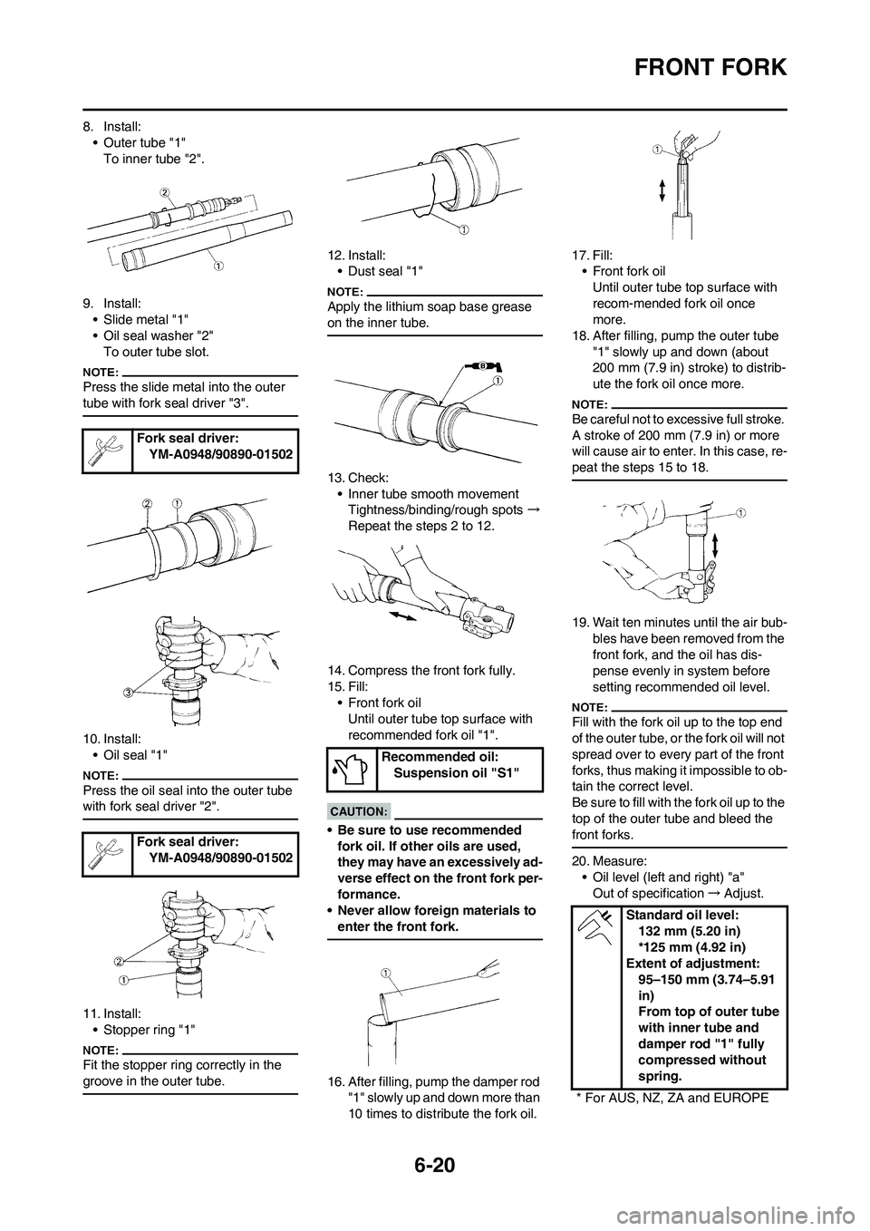
6-20
FRONT FORK
8. Install:
• Outer tube "1"
To inner tube "2".
9. Install:
• Slide metal "1"
• Oil seal washer "2"
To outer tube slot.
Press the slide metal into the outer
tube with fork seal driver "3".
10. Install:
• Oil seal "1"
Press the oil seal into the outer tube
with fork seal driver "2".
11. Install:
• Stopper ring "1"
Fit the stopper ring correctly in the
groove in the outer tube.
12. Install:
• Dust seal "1"
Apply the lithium soap base grease
on the inner tube.
13. Check:
• Inner tube smooth movement
Tightness/binding/rough spots →
Repeat the steps 2 to 12.
14. Compress the front fork fully.
15. Fill:
• Front fork oil
Until outer tube top surface with
recommended fork oil "1".
• Be sure to use recommended
fork oil. If other oils are used,
they may have an excessively ad-
verse effect on the front fork per-
formance.
• Never allow foreign materials to
enter the front fork.
16. After filling, pump the damper rod
"1" slowly up and down more than
10 times to distribute the fork oil.17. Fill:
• Front fork oil
Until outer tube top surface with
recom-mended fork oil once
more.
18. After filling, pump the outer tube
"1" slowly up and down (about
200 mm (7.9 in) stroke) to distrib-
ute the fork oil once more.
Be careful not to excessive full stroke.
A stroke of 200 mm (7.9 in) or more
will cause air to enter. In this case, re-
peat the steps 15 to 18.
19. Wait ten minutes until the air bub-
bles have been removed from the
front fork, and the oil has dis-
pense evenly in system before
setting recommended oil level.
Fill with the fork oil up to the top end
of the outer tube, or the fork oil will not
spread over to every part of the front
forks, thus making it impossible to ob-
tain the correct level.
Be sure to fill with the fork oil up to the
top of the outer tube and bleed the
front forks.
20. Measure:
• Oil level (left and right) "a"
Out of specification→Adjust. Fork seal driver:
YM-A0948/90890-01502
Fork seal driver:
YM-A0948/90890-01502
Recommended oil:
Suspension oil "S1"
Standard oil level:
132 mm (5.20 in)
*125 mm (4.92 in)
Extent of adjustment:
95–150 mm (3.74–5.91
in)
From top of outer tube
with inner tube and
damper rod "1" fully
compressed without
spring.
* For AUS, NZ, ZA and EUROPE
Page 182 of 224
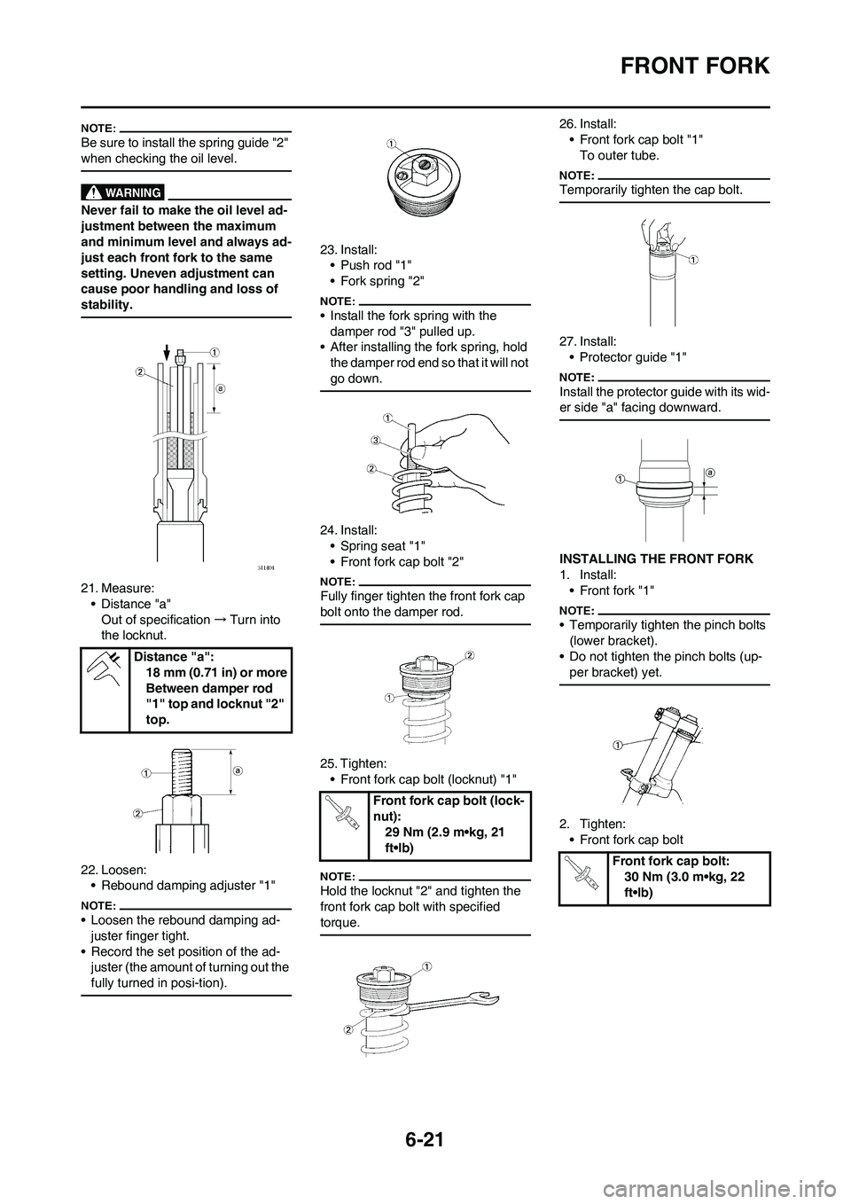
6-21
FRONT FORK
Be sure to install the spring guide "2"
when checking the oil level.
Never fail to make the oil level ad-
justment between the maximum
and minimum level and always ad-
just each front fork to the same
setting. Uneven adjustment can
cause poor handling and loss of
stability.
21. Measure:
• Distance "a"
Out of specification→Turn into
the locknut.
22. Loosen:
• Rebound damping adjuster "1"
• Loosen the rebound damping ad-
juster finger tight.
• Record the set position of the ad-
juster (the amount of turning out the
fully turned in posi-tion).
23. Install:
• Push rod "1"
• Fork spring "2"
• Install the fork spring with the
damper rod "3" pulled up.
• After installing the fork spring, hold
the damper rod end so that it will not
go down.
24. Install:
• Spring seat "1"
• Front fork cap bolt "2"
Fully finger tighten the front fork cap
bolt onto the damper rod.
25. Tighten:
• Front fork cap bolt (locknut) "1"
Hold the locknut "2" and tighten the
front fork cap bolt with specified
torque.
26. Install:
• Front fork cap bolt "1"
To outer tube.
Temporarily tighten the cap bolt.
27. Install:
• Protector guide "1"
Install the protector guide with its wid-
er side "a" facing downward.
INSTALLING THE FRONT FORK
1. Install:
• Front fork "1"
• Temporarily tighten the pinch bolts
(lower bracket).
• Do not tighten the pinch bolts (up-
per bracket) yet.
2. Tighten:
• Front fork cap bolt Distance "a":
18 mm (0.71 in) or more
Between damper rod
"1" top and locknut "2"
top.
Front fork cap bolt (lock-
nut):
29 Nm (2.9 m•kg, 21
ft•lb)
Front fork cap bolt:
30 Nm (3.0 m•kg, 22
ft•lb)