ECU YAMAHA WR 450F 2008 Owners Manual
[x] Cancel search | Manufacturer: YAMAHA, Model Year: 2008, Model line: WR 450F, Model: YAMAHA WR 450F 2008Pages: 224, PDF Size: 13.7 MB
Page 7 of 224
TO THE NEW OWNER
This manual will provide you with a
good basic understanding of fea-
tures, operation, and basic mainte-
nance and inspection items of this
machine. Please read this manual
carefully and completely before oper-
ating your new machine. If you have
any questions regarding the opera-
tion or maintenance of your machine,
please consult your Yamaha dealer.
This manual should be considered a
permanent part of this machine and
should remain with it even if the ma-
chine is subsequently sold.
NOTICE
Some data in this manual may be-
come outdated due to improve-
ments made to this model in the
future. If there is any question you
have regarding this manual or your
machine, please consult your
Yamaha dealer.
F.I.M. MACHINE WEIGHTS
Weights of machines without fuel
The minimum weights for motocross
machines are:
for the class 125 cc:
minimum 88 kg (194 lb)
for the class 250 cc:
minimum 98 kg (216 lb)
for the class 500 cc:
minimum 102 kg (225 lb)
In modifying your machine (e.g., for
weight reduction), take note of the
above limits of weight.
HOW TO USE THIS MANUAL
FINDING THE REQUIRED PAGE
1. This manual consists of seven
chapters; "General Information",
"Specifications", "Regular inspec-
tion and adjustments", "Tuning",
"Engine", "Chassis" and "Electri-
cal".
2. The table of contents is at the be-
ginning of the manual. Look over
the general layout of the book be-
fore finding then required chapter
and item.
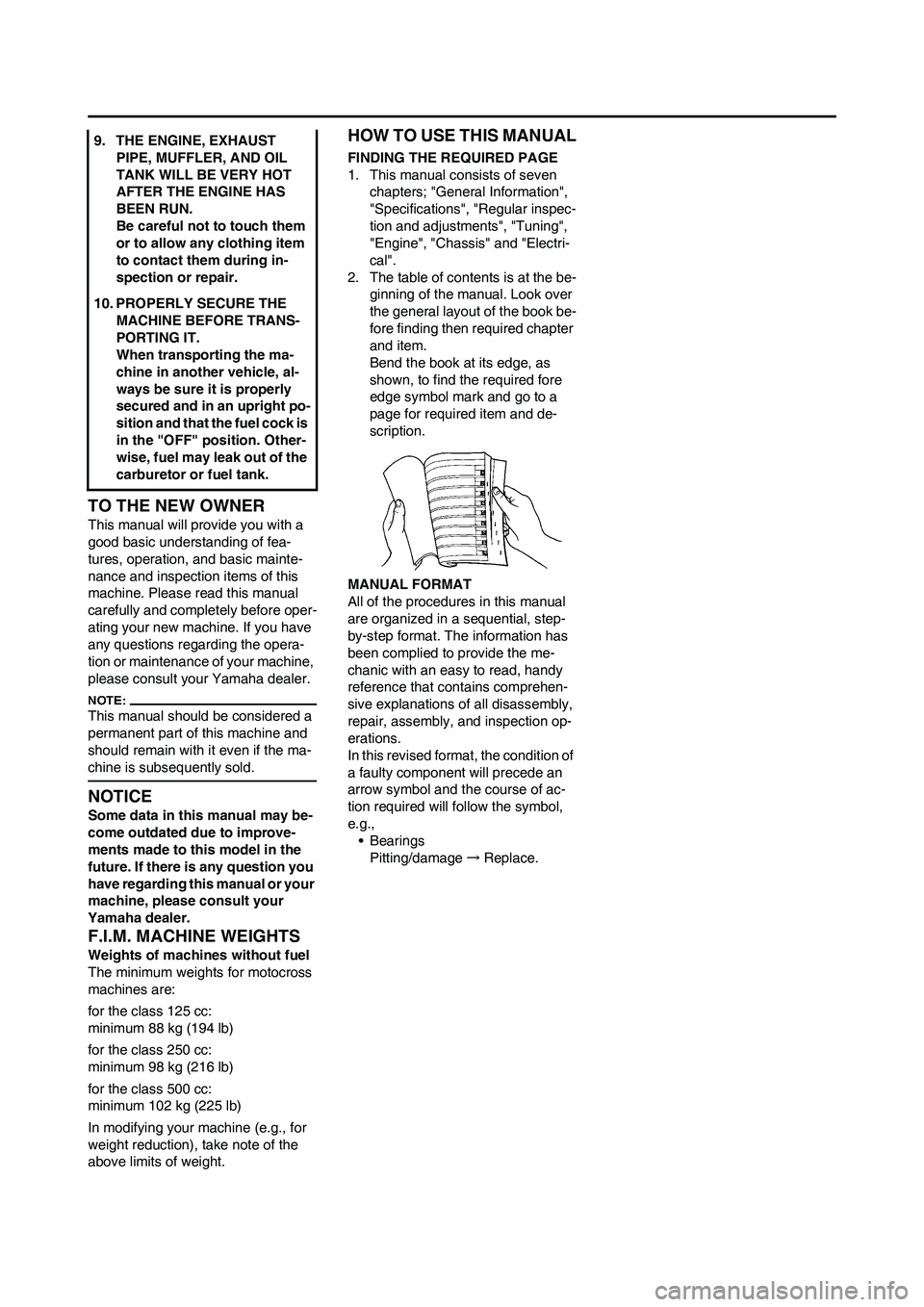
Bend the book at its edge, as
shown, to find the required fore
edge symbol mark and go to a
page for required item and de-
scription.
MANUAL FORMAT
All of the procedures in this manual
are organized in a sequential, step-
by-step format. The information has
been complied to provide the me-
chanic with an easy to read, handy
reference that contains comprehen-
sive explanations of all disassembly,
repair, assembly, and inspection op-
erations.
In this revised format, the condition of
a faulty component will precede an
arrow symbol and the course of ac-
tion required will follow the symbol,
e.g.,
•Bearings
Pitting/damage→Replace. 9. THE ENGINE, EXHAUST
PIPE, MUFFLER, AND OIL
TANK WILL BE VERY HOT
AFTER THE ENGINE HAS
BEEN RUN.
Be careful not to touch them
or to allow any clothing item
to contact them during in-
spection or repair.
10. PROPERLY SECURE THE
MACHINE BEFORE TRANS-
PORTING IT.
When transporting the ma-
chine in another vehicle, al-
ways be sure it is properly
secured and in an upright po-
sition and that the fuel cock is
in the "OFF" position. Other-
wise, fuel may leak out of the
carburetor or fuel tank.
Page 15 of 224
1-5
SPECIAL TOOLS
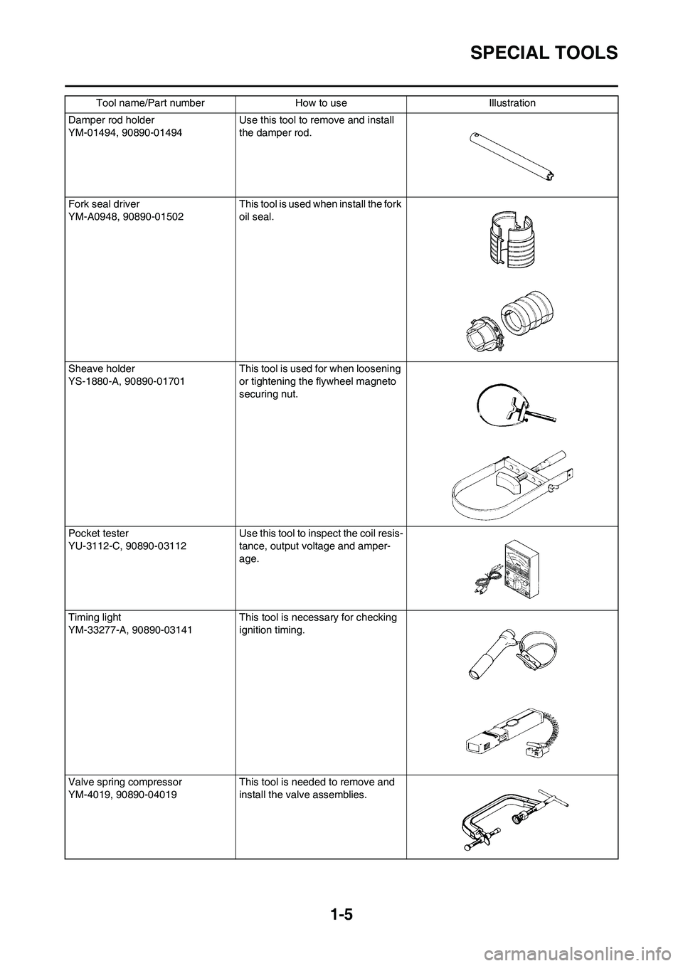
Damper rod holder
YM-01494, 90890-01494Use this tool to remove and install
the damper rod.
Fork seal driver
YM-A0948, 90890-01502 This tool is used when install the fork
oil seal.
Sheave holder
YS-1880-A, 90890-01701This tool is used for when loosening
or tightening the flywheel magneto
securing nut.
Pocket tester
YU-3112-C, 90890-03112 Use this tool to inspect the coil resis-
tance, output voltage and amper-
age.
Timing light
YM-33277-A, 90890-03141 This tool is necessary for checking
ignition timing.
Valve spring compressor
YM-4019, 90890-04019 This tool is needed to remove and
install the valve assemblies. Tool name/Part number How to use Illustration
Page 16 of 224
1-6
SPECIAL TOOLS
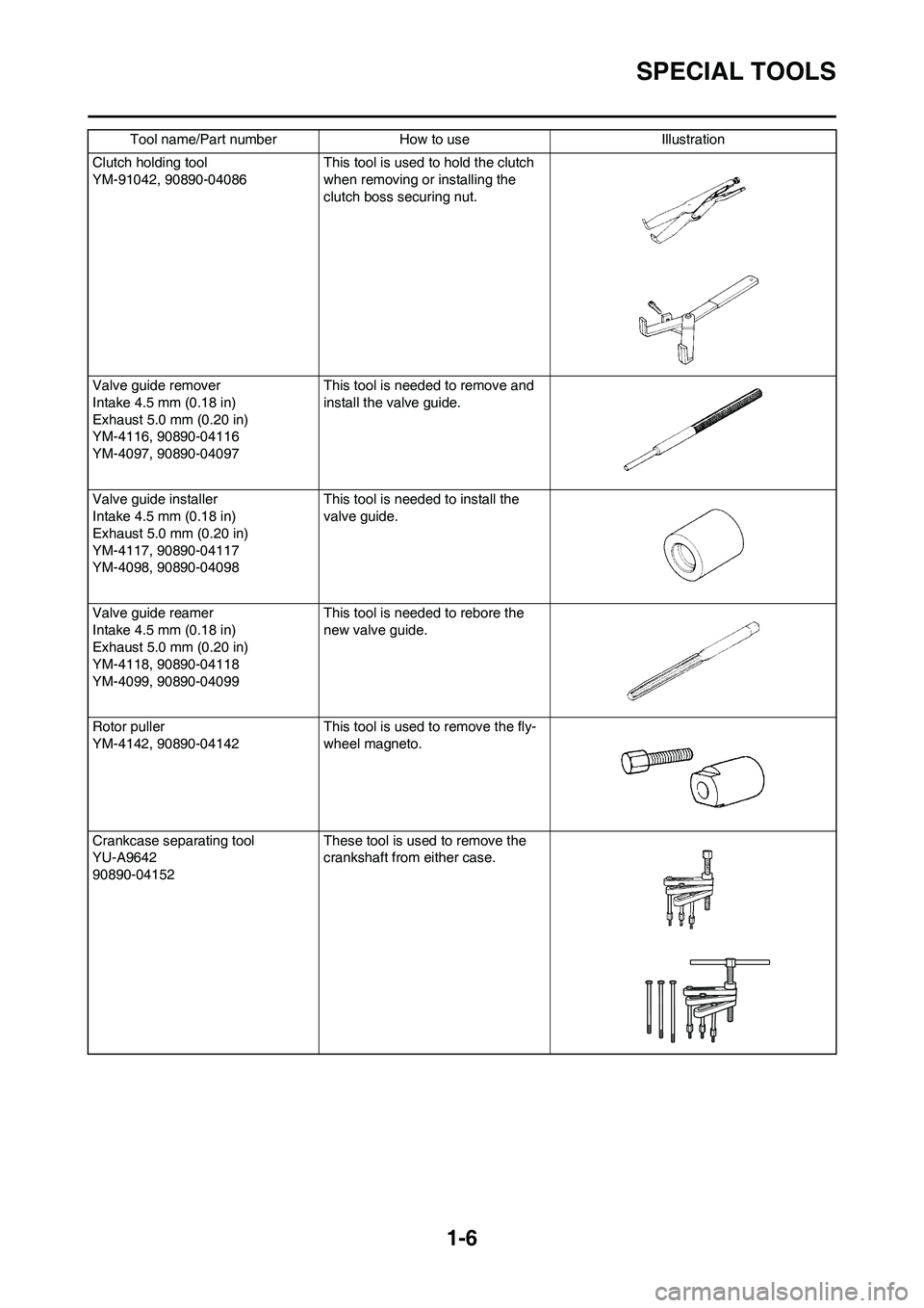
Clutch holding tool
YM-91042, 90890-04086 This tool is used to hold the clutch
when removing or installing the
clutch boss securing nut.
Valve guide remover
Intake 4.5 mm (0.18 in)
Exhaust 5.0 mm (0.20 in)
YM-4116, 90890-04116
YM-4097, 90890-04097This tool is needed to remove and
install the valve guide.
Valve guide installer
Intake 4.5 mm (0.18 in)
Exhaust 5.0 mm (0.20 in)
YM-4117, 90890-04117
YM-4098, 90890-04098This tool is needed to install the
valve guide.
Valve guide reamer
Intake 4.5 mm (0.18 in)
Exhaust 5.0 mm (0.20 in)
YM-4118, 90890-04118
YM-4099, 90890-04099This tool is needed to rebore the
new valve guide.
Rotor puller
YM-4142, 90890-04142This tool is used to remove the fly-
wheel magneto.
Crankcase separating tool
YU-A9642
90890-04152These tool is used to remove the
crankshaft from either case. Tool name/Part number How to use Illustration
Page 27 of 224

1-17
CLEANING AND STORAGE
CLEANING AND STORAGE
CLEANING
Frequent cleaning of your machine
will enhance its appearance, maintain
good overall performance, and ex-
tend the life of many components.
1. Before washing the machine,
block off the end of the exhaust
pipe to prevent water from enter-
ing. A plastic bag secured with a
rubber band may be used for this
purpose.
2. If the engine is excessively
greasy, apply some degreaser to
it with a paint brush. Do not apply
degreaser to the chain, sprockets,
or wheel axles.
3. Rinse the dirt and degreaser off
with a garden hose; use only
enough pressure to do the job.
Excessive hose pressure may
cause water seepage and contami-
nation of wheel bearings, front
forks, brakes and transmission
seals. Many expensive repair bills
have resulted from improper high
pressure detergent applications
such as those available in coin-op-
erated car washers.
4. After the majority of the dirt has
been hosed off, wash all surfaces
with warm water and a mild deter-
gent. Use an old toothbrush to
clean hard-to-reach places.
5. Rinse the machine off immediate-
ly with clean water, and dry all
surfaces with a soft towel or cloth.
6. Immediately after washing, re-
move excess water from the
chain with a paper towel and lubri-
cate the chain to prevent rust.
7. Clean the seat with a vinyl uphol-
stery cleaner to keep the cover
pliable and glossy.
8. Automotive wax may be applied
to all painted or chromed surfac-
es. Avoid combination cleaner-
waxes, as they may contain abra-
sives.
9. After completing the above, start
the engine and allow it to idle for
several minutes.STORAGE
If your machine is to be stored for 60
days or more, some preventive mea-
sures must be taken to avoid deterio-
ration. After cleaning the machine
thoroughly, prepare it for storage as
follows:
1. Drain the fuel tank, fuel lines, and
the carburetor float bowl.
2. Remove the spark plug, pour a ta-
blespoon of SAE 10W-30 motor
oil in the spark plug hole, and re-
install the plug. With the engine
stop switch pushed in, kick the en-
gine over several times to coat the
cylinder walls with oil.
3. Remove the drive chain, clean it
thoroughly with solvent, and lubri-
cate it. Reinstall the chain or store
it in a plastic bag tied to the frame.
4. Lubricate all control cables.
5. Block the frame up to raise the
wheels off the ground.
6. Tie a plastic bag over the exhaust
pipe outlet to prevent moisture
from entering.
7. If the machine is to be stored in a
humid or salt-air environment,
coat all exposed metal surfaces
with a film of light oil. Do not apply
oil to rubber parts or the seat cov-
er.
Make any necessary repairs before
the machine is stored.
Page 49 of 224

2-22
CABLE ROUTING DIAGRAM
C. Fasten the diode (at the mark-
ing), throttle cable and hot start-
er cable onto the frame. Locate
the clamp end facing toward the
lower right of the frame and with
the tie end facing downward.
D. Fasten the wire harness, throttle
position sensor lead and clutch
cable onto the frame. Pass the
clamp through the hole in the
stay (air cut-off valve). Locate
the clamp end facing toward the
lower side of the frame and cut
off the tie end.
E. Fasten the throttle position sen-
sor lead onto the frame. Locate
the clamp end facing toward the
lower side of the frame and cut
off the tie end.
F. Pass the carburetor breather
hoses, carburetor overflow hose
and catch tank breather hose
between the connecting rod and
cross tube (frame).
G. Pass the neutral switch lead on
the inside of the engine bracket.
H. Fasten the neutral switch lead
and AC magneto lead onto the
frame. Locate the clamp end
facing toward the outside of the
frame and tie end facing toward
the rear of the frame.
I. Fasten the AC magneto lead
and neutral switch lead onto the
frame. Locate the clamp end
facing toward the rear of the
frame and cut off the tie end.
J. Pass the neutral switch lead and
AC magneto lead on the inside
of the wire harness.
K. Fasten the AC magneto lead
and neutral switch lead onto the
frame.
L. Pass the wire harness through
the cable guide.
M. Locate the couplers in the frame
recess.
N. Pass the carburetor breather
hoses, carburetor overflow hose
and catch tank breather hose so
that the hoses do not contact the
rear shock absorber.
O. Secure the coupler by pushing it
into the hole in the headlight
unit.
Page 52 of 224

2-25
CABLE ROUTING DIAGRAM
1. Clamp
2. Positive battery lead
3. Battery
4. Negative battery lead
5. Taillight coupler
6. CDI unit coupler (6-pin)
7. CDI unit coupler (3-pin)
8. CDI unit coupler (6-pin)A. Fasten the wire harness to the
upper engine bracket (left side).
Locate the clamp end facing to-
ward the upper side of the frame
with the tie end cut off on the in-
side of the frame.B. Fasten the wire harness to the
upper engine bracket (left side).
Locate the clamp end facing to-
ward the upper side of the frame
with the tie end cut off on the in-
side of the frame. Clamp the
wire harness at the marking.
C. Pass the starter motor lead
through the hole in the relay
holder.
D. Fit the cover securely.
Page 55 of 224

2-28
CABLE ROUTING DIAGRAM
D. Secure the coupler by inserting
it into the multi-function display
bracket.
E. Pass the throttle cables, clutch
cable and hot starter cable be-
tween the upper bracket and
multi-function display bracket.
F. Fasten the multi-function display
leads to the bracket. Cut off the
tie end.
G. Secure the coupler by pushing it
into the hole in the multi-function
display bracket.
H. Secure the wire harness clip by
pushing it into the hole in the
multi-function display bracket on
the inside.
I. Fasten the main switch lead
(wire harness side) to the multi-
function display bracket. Locate
the clamp end facing toward the
lower side of the frame and cut
off the tie end.
J. Pass the speed sensor lead
through the guide on the outside
of the front fork.
Page 122 of 224

5-26
VALVES AND VALVE SPRINGS
CHECKING THE VALVE SPRINGS
1. Measure:
• Valve spring free length "a"
Out of specification→Replace.
2. Measure:
• Compressed spring force "a"
Out of specification→Replace.
b. Installed length
3. Measure:
• Spring tilt "a"
Out of specification→Replace.CHECKING THE VALVE LIFTERS
1. Inspect:
• Valve lifter
Scratches/damage→Replace
both lifters and cylinder head.
INSTALLING THE VALVES
1. Apply:
• Molybdenum disulfide oil
Onto the valve stem and valve
stem seal.
2. Install:
• Valves "1"
• Valve spring seats "2"
• Valve stem seals "3"
• Valve springs "4"
• Valve spring retainers "5"
• Make sure that each valve is in-
stalled in its original place, also re-
ferring to the painted color as
follows.
Intake (middle) "a": blue
Intake (right/left) "b": gray
Exhaust "c": brown
• Install the valve springs with the
larger pitch "d" facing upward.
e. Smaller pitch3. Install:
• Valve cotters
While compressing the valve spring
with a valve spring compressor "1" in-
stall the valve cotters.
4. To secure the valve cotters onto
the valve stem, lightly tap the
valve tip with a piece of wood.
Hitting the valve tip with excessive
force could damage the valve.
5. Install:
• Adjusting pad "1"
• Valve lifter "2"
• Apply the molybdenum disulfide oil
on the valve stem end.
• Apply the engine oil on the valve lift-
ers.
• Valve lifter must turn smoothly
when rotated with a finger.
• Be careful to reinstall valve lifters
and pads in their original place.
Free length (valve
spring):
Intake:
39.46 mm (1.55 in)
(1.51 in)
Exhaust:
37.61 mm (1.48 in)
(1.44 in)
Compressed spring
force:
Intake:
130.2–149.8 N at 27.87
mm (13.28–15.28 kg at
27.87 mm, 29.27–
33.68 lb at 1.10 in)
Exhaust:
123.1–141.7 N at 28.38
mm (12.55–14.45 kg at
28.38 mm, 27.67–
31.85 lb at 1.12 in)
Spring tilt limit:
Intake:
2.5°/1.7 mm (0.067 in)
Exhaust:
2.5°/1.6 mm (0.063 in)
Valve spring compres-
sor:
YM-4019/90890-04019
Page 151 of 224
5-55
ENGINE REMOVAL
HANDLING NOTE
Support the machine securely so
there is no danger of it falling over.
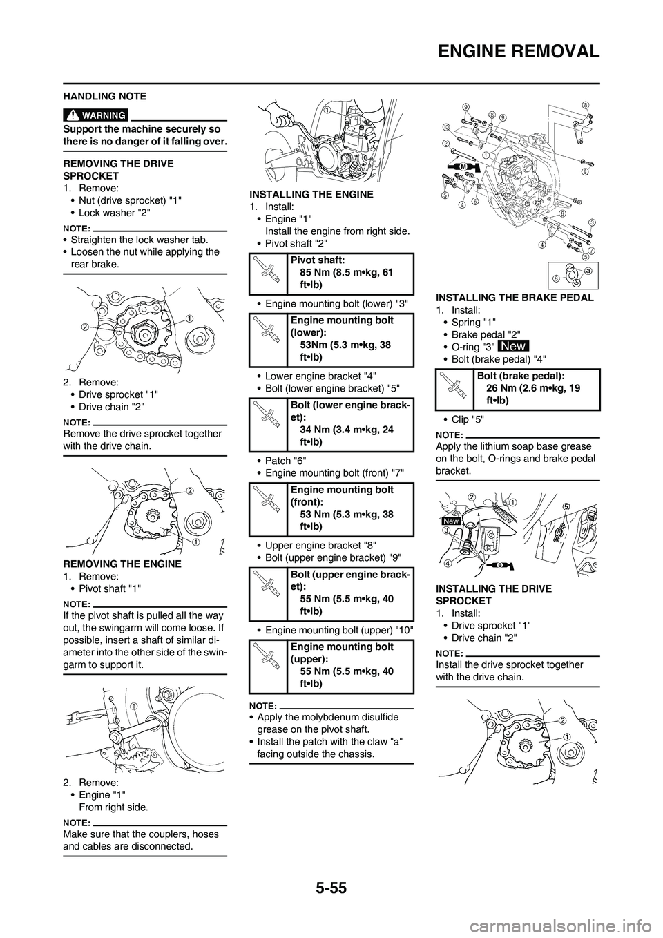
REMOVING THE DRIVE
SPROCKET
1. Remove:
• Nut (drive sprocket) "1"
• Lock washer "2"
• Straighten the lock washer tab.
• Loosen the nut while applying the
rear brake.
2. Remove:
• Drive sprocket "1"
• Drive chain "2"
Remove the drive sprocket together
with the drive chain.
REMOVING THE ENGINE
1. Remove:
• Pivot shaft "1"
If the pivot shaft is pulled all the way
out, the swingarm will come loose. If
possible, insert a shaft of similar di-
ameter into the other side of the swin-
garm to support it.
2. Remove:
• Engine "1"
From right side.
Make sure that the couplers, hoses
and cables are disconnected.
INSTALLING THE ENGINE
1. Install:
• Engine "1"
Install the engine from right side.
• Pivot shaft "2"
• Engine mounting bolt (lower) "3"
• Lower engine bracket "4"
• Bolt (lower engine bracket) "5"
• Patch "6"
• Engine mounting bolt (front) "7"
• Upper engine bracket "8"
• Bolt (upper engine bracket) "9"
• Engine mounting bolt (upper) "10"
• Apply the molybdenum disulfide
grease on the pivot shaft.
• Install the patch with the claw "a"
facing outside the chassis.
INSTALLING THE BRAKE PEDAL
1. Install:
• Spring "1"
• Brake pedal "2"
• O-ring "3"
• Bolt (brake pedal) "4"
• Clip "5"
Apply the lithium soap base grease
on the bolt, O-rings and brake pedal
bracket.
INSTALLING THE DRIVE
SPROCKET
1. Install:
• Drive sprocket "1"
• Drive chain "2"
Install the drive sprocket together
with the drive chain.
Pivot shaft:
85 Nm (8.5 m•kg, 61
ft•lb)
Engine mounting bolt
(lower):
53Nm (5.3 m•kg, 38
ft•lb)
Bolt (lower engine brack-
et):
34 Nm (3.4 m•kg, 24
ft•lb)
Engine mounting bolt
(front):
53 Nm (5.3 m•kg, 38
ft•lb)
Bolt (upper engine brack-
et):
55 Nm (5.5 m•kg, 40
ft•lb)
Engine mounting bolt
(upper):
55 Nm (5.5 m•kg, 40
ft•lb)
Bolt (brake pedal):
26 Nm (2.6 m•kg, 19
ft•lb)
Page 164 of 224
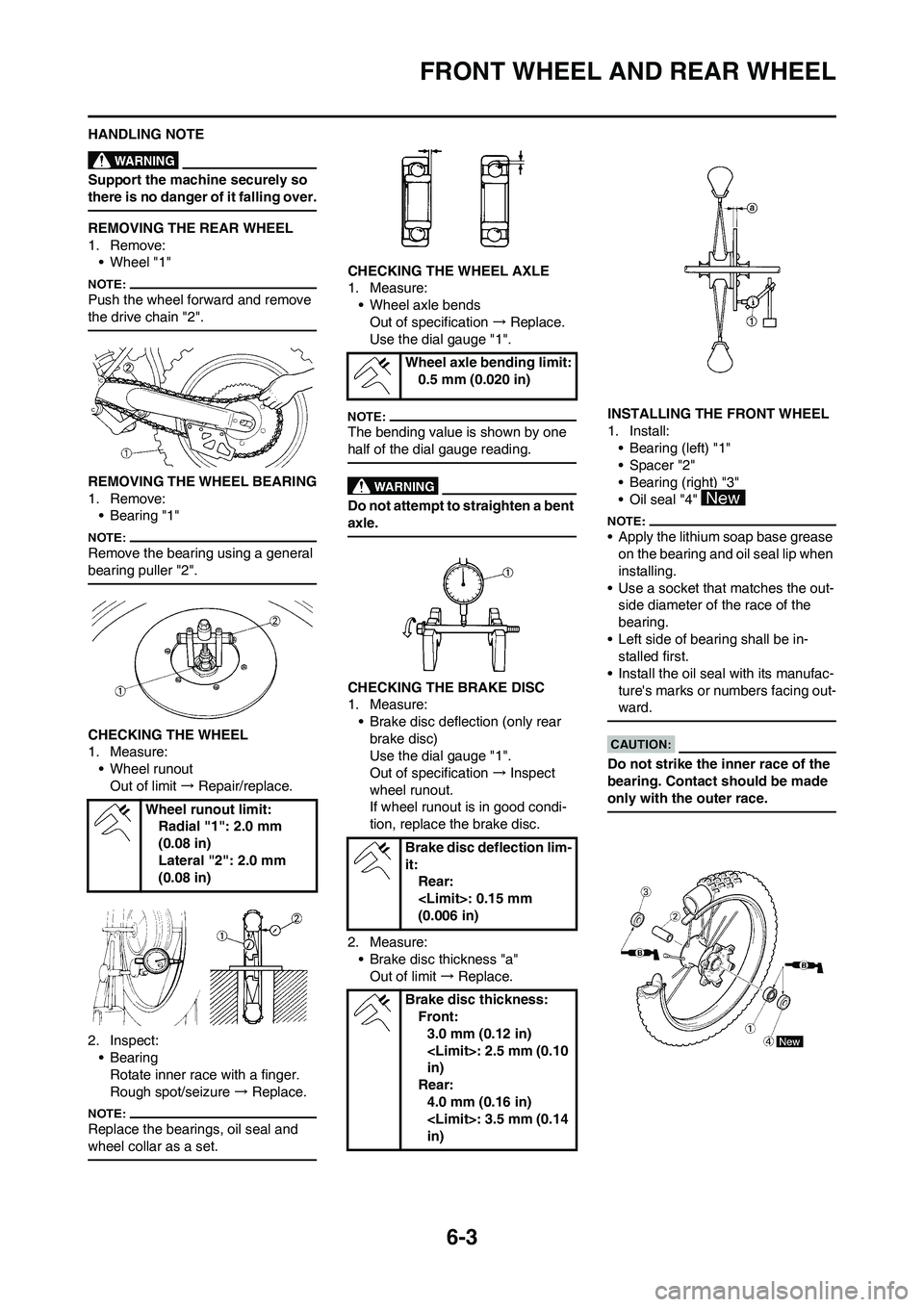
6-3
FRONT WHEEL AND REAR WHEEL
HANDLING NOTE
Support the machine securely so
there is no danger of it falling over.
REMOVING THE REAR WHEEL
1. Remove:
• Wheel "1"
Push the wheel forward and remove
the drive chain "2".
REMOVING THE WHEEL BEARING
1. Remove:
• Bearing "1"
Remove the bearing using a general
bearing puller "2".
CHECKING THE WHEEL
1. Measure:
• Wheel runout
Out of limit → Repair/replace.
2. Inspect:
• Bearing
Rotate inner race with a finger.
Rough spot/seizure → Replace.
Replace the bearings, oil seal and
wheel collar as a set.
CHECKING THE WHEEL AXLE
1. Measure:
• Wheel axle bends
Out of specification → Replace.
Use the dial gauge "1".
The bending value is shown by one
half of the dial gauge reading.
Do not attempt to straighten a bent
axle.
CHECKING THE BRAKE DISC
1. Measure:
• Brake disc deflection (only rear
brake disc)
Use the dial gauge "1".
Out of specification → Inspect
wheel runout.
If wheel runout is in good condi-
tion, replace the brake disc.
2. Measure:
• Brake disc thickness "a"
Out of limit → Replace.INSTALLING THE FRONT WHEEL
1. Install:
• Bearing (left) "1"
• Spacer "2"
• Bearing (right) "3"
• Oil seal "4"
• Apply the lithium soap base grease
on the bearing and oil seal lip when
installing.
• Use a socket that matches the out-
side diameter of the race of the
bearing.
• Left side of bearing shall be in-
stalled first.
• Install the oil seal with its manufac-
ture's marks or numbers facing out-
ward.
Do not strike the inner race of the
bearing. Contact should be made
only with the outer race.
Wheel runout limit:
Radial "1": 2.0 mm
(0.08 in)
Lateral "2": 2.0 mm
(0.08 in)
Wheel axle bending limit:
0.5 mm (0.020 in)
Brake disc deflection lim-
it:
Rear:
(0.006 in)
Brake disc thickness:
Front:
3.0 mm (0.12 in)
in)
Rear:
4.0 mm (0.16 in)
in)