air filter YAMAHA WR 450F 2008 Owners Manual
[x] Cancel search | Manufacturer: YAMAHA, Model Year: 2008, Model line: WR 450F, Model: YAMAHA WR 450F 2008Pages: 224, PDF Size: 13.7 MB
Page 10 of 224
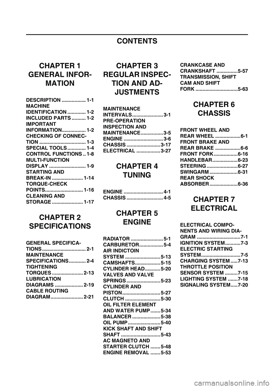
CONTENTS
CHAPTER 1
GENERAL INFOR-
MATION
DESCRIPTION ................. 1-1
MACHINE
IDENTIFICATION ............. 1-2
INCLUDED PARTS .......... 1-2
IMPORTANT
INFORMATION................. 1-2
CHECKING OF CONNEC-
TION ................................. 1-3
SPECIAL TOOLS ............. 1-4
CONTROL FUNCTIONS .. 1-8
MULTI-FUNCTION
DISPLAY .......................... 1-9
STARTING AND
BREAK-IN ...................... 1-14
TORQUE-CHECK
POINTS........................... 1-16
CLEANING AND
STORAGE ...................... 1-17
CHAPTER 2
SPECIFICATIONS
GENERAL SPECIFICA-
TIONS ............................... 2-1
MAINTENANCE
SPECIFICATIONS ............ 2-4
TIGHTENING
TORQUES ...................... 2-13
LUBRICATION
DIAGRAMS .................... 2-19
CABLE ROUTING
DIAGRAM ....................... 2-21
CHAPTER 3
REGULAR INSPEC-
TION AND AD-
JUSTMENTS
MAINTENANCE
INTERVALS ...................... 3-1
PRE-OPERATION
INSPECTION AND
MAINTENANCE................ 3-5
ENGINE ............................ 3-6
CHASSIS ........................ 3-17
ELECTRICAL ................. 3-27
CHAPTER 4
TUNING
ENGINE ............................ 4-1
CHASSIS .......................... 4-5
CHAPTER 5
ENGINE
RADIATOR ....................... 5-1
CARBURETOR................. 5-4
AIR INDICTOIN
SYSTEM ......................... 5-13
CAMSHAFTS.................. 5-15
CYLINDER HEAD........... 5-20
VALVES AND VALVE
SPRINGS ........................ 5-23
CYLINDER AND
PISTON ........................... 5-27
CLUTCH ......................... 5-30
OIL FILTER ELEMENT
AND WATER PUMP ....... 5-34
BALANCER .................... 5-38
OIL PUMP ....................... 5-40
KICK SHAFT AND SHIFT
SHAFT ............................ 5-43
AC MAGNETO AND
STARTER CLUTCH ....... 5-48
ENGINE REMOVAL ....... 5-53CRANKCASE AND
CRANKSHAFT ...............5-57
TRANSMISSION, SHIFT
CAM AND SHIFT
FORK ..............................5-63
CHAPTER 6
CHASSIS
FRONT WHEEL AND
REAR WHEEL ..................6-1
FRONT BRAKE AND
REAR BRAKE ..................6-6
FRONT FORK .................6-16
HANDLEBAR..................6-23
STEERING ......................6-27
SWINGARM ....................6-31
REAR SHOCK
ABSORBER ....................6-36
CHAPTER 7
ELECTRICAL
ELECTRICAL COMPO-
NENTS AND WIRING DIA-
GRAM ...............................7-1
IGNITION SYSTEM...........7-3
ELECTRIC STARTING
SYSTEM............................7-5
CHARGING SYSTEM .....7-13
THROTTLE POSITION
SENSOR SYSTEM .........7-15
LIGHTING SYSTEM .......7-18
SIGNALING SYSTEM.....7-20
Page 24 of 224
1-14
STARTING AND BREAK-IN
STARTING AND BREAK-IN
FUEL
Always use the recommended fuel as
stated below. Also, be sure to use
new gasoline the day of a race.
Use only unleaded gasoline. The
use of leaded gasoline will cause
severe damage to the engine inter-
nal parts such as valves, piston
rings, and exhaust system, etc.
If knocking or pinging occurs, use a
different brand of gasoline or higher
octane grade.
• For refueling, be sure to stop the
engine and use enough care not
to spill any fuel. Also be sure to
avoid refueling close to a fire.
• Refuel after the engine, exhaust
pipe, etc. have cooled off.
HANDLING NOTE
Never start or run the engine in a
closed area. The exhaust fumes
are poisonous; they can cause
loss of consciousness and death
in a very short time. Always oper-
ate the machine in a well-ventilated
area.
• The carburetor on this machine
has a built-in accelerator pump.
Therefore, when starting the en-
gine, do not operate the throttle
or the spark plug will foul.
• Unlike a two-stroke engine, this
engine cannot be kick started
when the throttle is open be-
cause the kickstarter may kick
back. Also, if the throttle is open
the air/fuel mixture may be too
lean for the engine to start.
• Before starting the machine, per-
form the checks in the pre-opera-
tion check list.
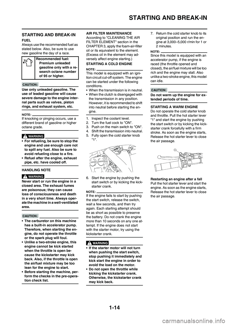
AIR FILTER MAINTENANCE
According to "CLEANING THE AIR
FILTER ELEMENT" section in the
CHAPTER 3, apply the foam-air-filter
oil or its equivalent to the element.
(Excess oil in the element may ad-
versely affect engine starting.)
STARTING A COLD ENGINE
This model is equipped with an igni-
tion circuit cut-off system. The engine
can be started under the following
conditions.
• When the transmission is in neutral.
• When the clutch is disengaged with
the transmission in any position.
However, it is recommended to shift
into neutral before starting the en-
gine.
1. Inspect the coolant level.
2. Turn the fuel cock to "ON".
3. Push on the main switch to "ON".
4. Shift the transmission into neutral.
5. Fully open the cold starter knob
"1".
6. Start the engine by pushing the
start switch or by kicking the kick-
starter crank.
If the engine fails to start by pushing
the start switch, release the switch,
wait a few seconds, and then try
again. Each starting attempt should
be as short as possible to preserve
the battery. Do not crank the engine
more than 10 seconds on any one at-
tempt. If the engine does not start
with the starter motor, try using the
kickstarter crank.
• If the starter motor will not turn
when pushing the start switch,
stop pushing it immediately and
kick start the engine in order to
avoid the load on the motor.
• Do not open the throttle while
kicking the kickstarter crank.
Otherwise, the kickstarter crank
may kick back.
7. Return the cold starter knob to its
original position and run the en-
gine at 3,000–5,000 r/min for 1 or
2 minutes.
Since this model is equipped with an
accelerator pump, if the engine is
raced (the throttle opened and
closed), the air/fuel mixture will be too
rich and the engine may stall. Also
unlike a two-stroke engine, this model
can idle.
Do not warm up the engine for ex-
tended periods of time.
STARTING A WARM ENGINE
Do not operate the cold starter knob
and throttle. Pull the hot starter lever
"1" and start the engine by pushing
the start switch or by kicking the kick-
starter crank forcefully with a firm
stroke. As soon as the engine starts,
Release the hot starter lever to close
the air passage.
Restarting an engine after a fall
Pull the hot starter lever and start the
engine. As soon as the engine starts,
Release the hot starter lever to close
the air passage. Recommended fuel:
Premium unleaded
gasoline only with a re-
search octane number
of 95 or higher.
Page 29 of 224
2-2
GENERAL SPECIFICATIONS
(Except for CDN)
SAE10W30, SAE10W40, SAE15W40,
SAE20W40 or SAE20W50
API service SG type or higher,
JASO standard MA
Oil capacity:
Engine oil
Periodic oil change 0.95 L (0.84 Imp qt, 1.00 US qt)
With oil filter replacement 1.0 L (0.88 Imp qt, 1.06 US qt)
Total amount 1.2 L (1.06 Imp qt, 1.27 US qt)
Coolant capacity (including all routes): 1.0 L (0.88 Imp qt, 1.06 US qt)
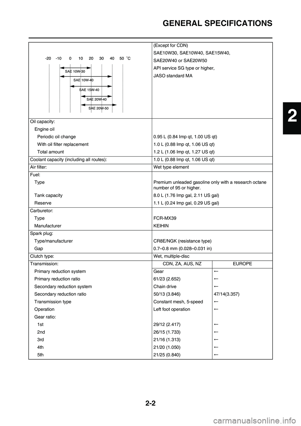
Air filter: Wet type element
Fuel:
Type Premium unleaded gasoline only with a research octane
number of 95 or higher.
Tank capacity 8.0 L (1.76 Imp gal, 2.11 US gal)
Reserve 1.1 L (0.24 Imp gal, 0.29 US gal)
Carburetor:
Type FCR-MX39
Manufacturer KEIHIN
Spark plug:
Type/manufacturer CR8E/NGK (resistance type)
Gap 0.7–0.8 mm (0.028–0.031 in)
Clutch type: Wet, multiple-disc
Transmission: CDN, ZA, AUS, NZ EUROPE
Primary reduction system Gear←
Primary reduction ratio 61/23 (2.652)←
Secondary reduction system Chain drive←
Secondary reduction ratio 50/13 (3.846) 47/14(3.357)
Transmission type Constant mesh, 5-speed←
Operation Left foot operation←
Gear ratio:
1st 29/12 (2.417)←
2nd 26/15 (1.733)←
3rd 21/16 (1.313)←
4th 21/20 (1.050)←
5th 21/25 (0.840)←
2
Page 34 of 224
2-7
MAINTENANCE SPECIFICATIONS
Piston rings:
Top ring:
Type Barrel ----
Dimensions (B × T) 1.2 × 3.5 mm (0.05 × 0.14 in) ----
End gap (installed) 0.20–0.30 mm (0.008–0.012 in) 0.55 mm (0.022
in)
Side clearance (installed) 0.030–0.065 mm (0.0012–0.0026 in) 0.12 mm (0.005
in)
2nd ring:
Type Taper ----
Dimensions (B × T) 1.00 × 3.35 mm (0.04 × 0.13 in) ----
End gap (installed) 0.35–0.50 mm (0.014–0.020 in) 0.85 mm (0.033
in)
Side clearance 0.020–0.055 mm (0.0008–0.0022 in) 0.12 mm (0.005
in)
Oil ring:
Dimensions (B × T) 2.0 × 2.9 mm (0.08 × 0.11 in) ----
End gap (installed) 0.2–0.5 mm (0.01–0.02 in) ----
Crankshaft:
Crank width "A" 61.95–62.00 mm (2.439–2.441 in) ----
Runout limit "C" 0.03 mm (0.0012 in) 0.05 mm (0.002
in)
Big end side clearance "D" 0.15–0.45 mm (0.0059–0.0177 in) 0.50 mm (0.02
in)
Small end free play "F" 0.4–1.0 mm (0.02–0.04 in) 2.0 mm (0.08
in)
Balancer:
Balancer drive method Gear ----
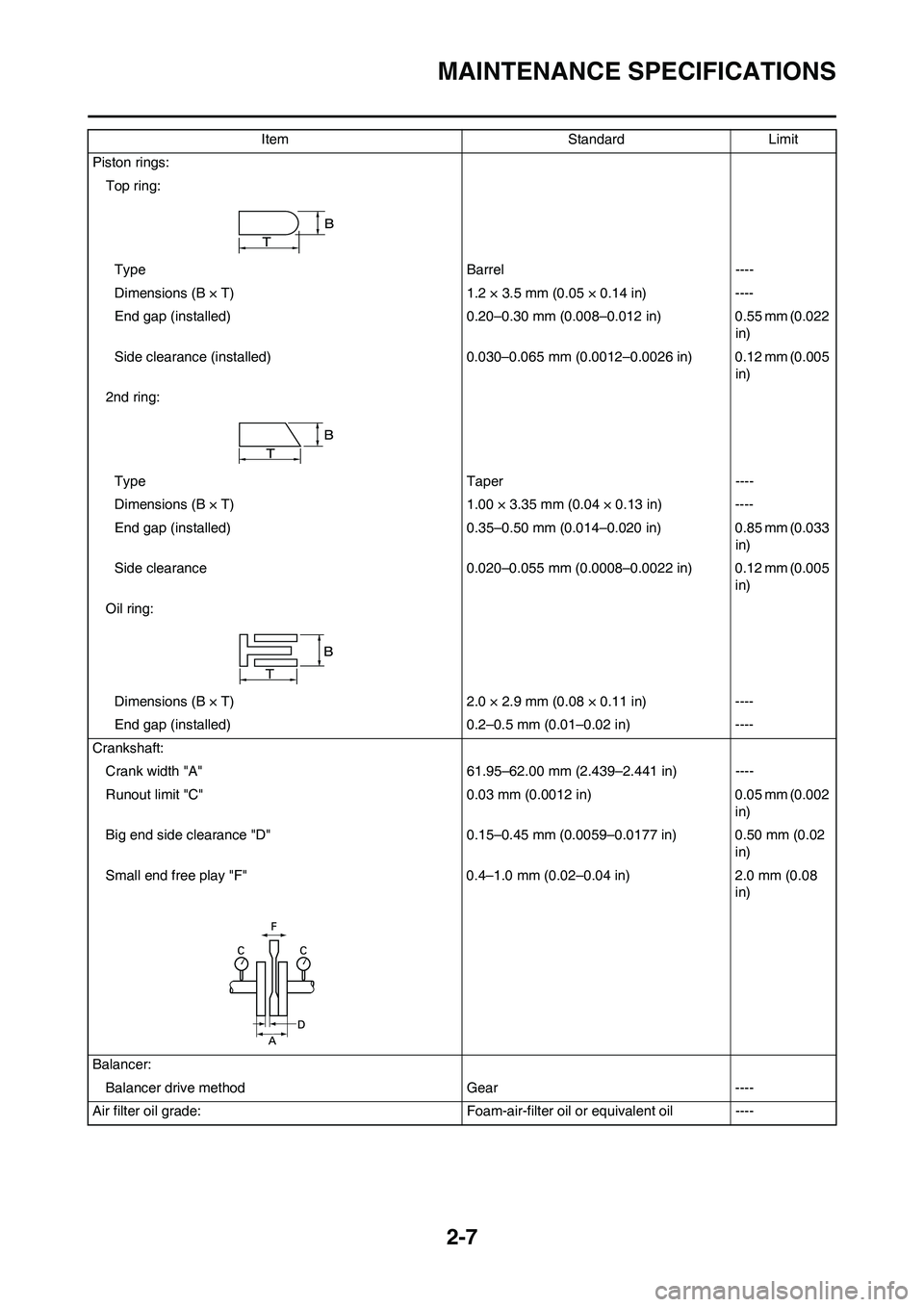
Air filter oil grade: Foam-air-filter oil or equivalent oil ----Item Standard Limit
Page 40 of 224
2-13
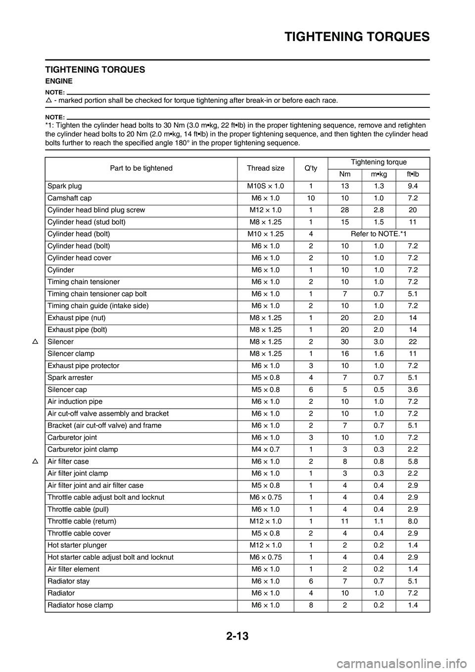
TIGHTENING TORQUES
TIGHTENING TORQUES
ENGINE
△- marked portion shall be checked for torque tightening after break-in or before each race.
*1: Tighten the cylinder head bolts to 30 Nm (3.0 m•kg, 22 ft•lb) in the proper tightening sequence, remove and retighten
the cylinder head bolts to 20 Nm (2.0 m•kg, 14 ft•lb) in the proper tightening sequence, and then tighten the cylinder head
bolts further to reach the specified angle 180° in the proper tightening sequence.
Part to be tightened Thread size Q'tyTightening torque
Nm m•kg ft•lb
Spark plug M10S × 1.0 1 13 1.3 9.4
Camshaft cap M6 × 1.0 10 10 1.0 7.2
Cylinder head blind plug screw M12 × 1.0 1 28 2.8 20
Cylinder head (stud bolt) M8 × 1.25 1 15 1.5 11
Cylinder head (bolt) M10 × 1.25 4 Refer to NOTE.*1
Cylinder head (bolt) M6 × 1.0 2 10 1.0 7.2
Cylinder head cover M6 × 1.0 2 10 1.0 7.2
Cylinder M6 × 1.0 1 10 1.0 7.2
Timing chain tensioner M6 × 1.0 2 10 1.0 7.2
Timing chain tensioner cap bolt M6 × 1.0 1 7 0.7 5.1
Timing chain guide (intake side) M6 × 1.0 2 10 1.0 7.2
Exhaust pipe (nut) M8 × 1.25 1 20 2.0 14
Exhaust pipe (bolt) M8 × 1.25 1 20 2.0 14
△Silencer M8 × 1.25 2 30 3.0 22
Silencer clamp M8 × 1.25 1 16 1.6 11
Exhaust pipe protector M6 × 1.0 3 10 1.0 7.2
Spark arrester M5 × 0.8 4 7 0.7 5.1
Silencer cap M5 × 0.8 6 5 0.5 3.6
Air induction pipe M6 × 1.0 2 10 1.0 7.2
Air cut-off valve assembly and bracket M6 × 1.0 2 10 1.0 7.2
Bracket (air cut-off valve) and frame M6 × 1.0 2 7 0.7 5.1
Carburetor joint M6 × 1.0 3 10 1.0 7.2
Carburetor joint clamp M4 × 0.7 1 3 0.3 2.2
△Air filter case M6 × 1.0 2 8 0.8 5.8
Air filter joint clamp M6 × 1.0 1 3 0.3 2.2
Air filter joint and air filter case M5 × 0.8 1 4 0.4 2.9
Throttle cable adjust bolt and locknut M6 × 0.75 1 4 0.4 2.9
Throttle cable (pull) M6 × 1.0 1 4 0.4 2.9
Throttle cable (return) M12 × 1.0 1 11 1.1 8.0
Throttle cable cover M5 × 0.8 2 4 0.4 2.9
Hot starter plunger M12 × 1.0 1 2 0.2 1.4
Hot starter cable adjust bolt and locknut M6 × 0.75 1 4 0.4 2.9
Air filter element M6 × 1.0 1 2 0.2 1.4
Radiator stay M6 × 1.0 6 7 0.7 5.1
Radiator M6 × 1.0 4 10 1.0 7.2
Radiator hose clamp M6 × 1.0 8 2 0.2 1.4
Page 57 of 224
3-2
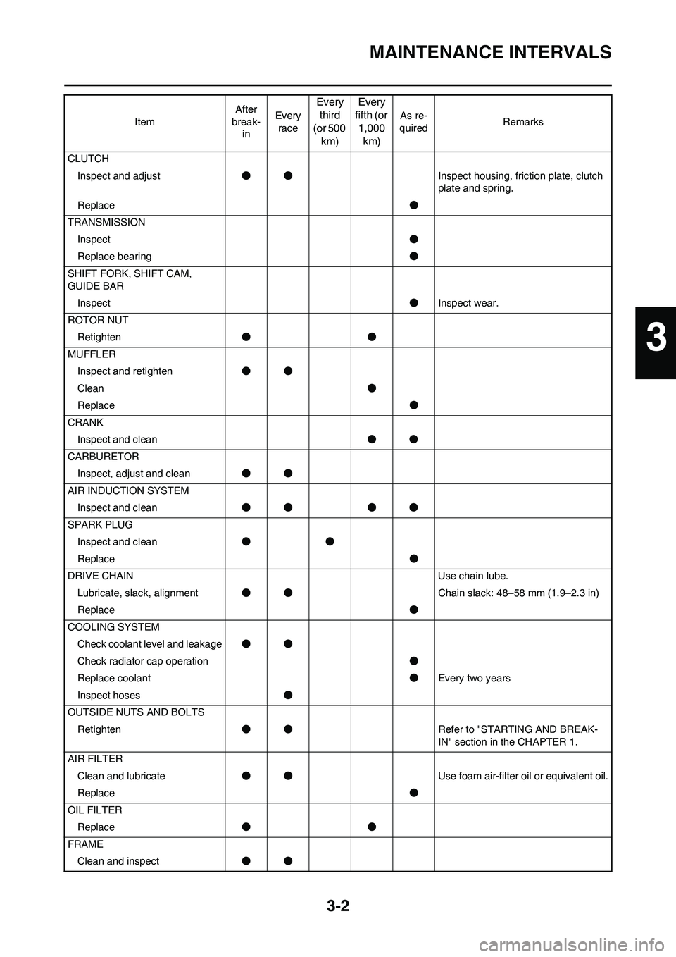
MAINTENANCE INTERVALS
CLUTCH
Inspect and adjust●●Inspect housing, friction plate, clutch
plate and spring.
Replace●
TRANSMISSION
Inspect●
Replace bearing●
SHIFT FORK, SHIFT CAM,
GUIDE BAR
Inspect●Inspect wear.
ROTOR NUT
Retighten●●
MUFFLER
Inspect and retighten●●
Clean●
Replace●
CRANK
Inspect and clean●●
CARBURETOR
Inspect, adjust and clean●●
AIR INDUCTION SYSTEM
Inspect and clean●● ●●
SPARK PLUG
Inspect and clean●●
Replace●
DRIVE CHAIN Use chain lube.
Lubricate, slack, alignment●●Chain slack: 48–58 mm (1.9–2.3 in)
Replace●
COOLING SYSTEM
Check coolant level and leakage●●
Check radiator cap operation●
Replace coolant●Every two years
Inspect hoses●
OUTSIDE NUTS AND BOLTS
Retighten●●Refer to "STARTING AND BREAK-
IN" section in the CHAPTER 1.
AIR FILTER
Clean and lubricate●●Use foam air-filter oil or equivalent oil.
Replace●
OIL FILTER
Replace●●
FRAME
Clean and inspect●● ItemAfter
break-
inEvery
race
Every
third
(or 500
km)Every
fifth (or
1,000
km)
As re-
quiredRemarks
3
Page 61 of 224
3-6
ENGINE
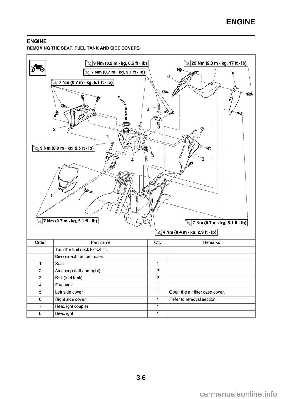
ENGINE
REMOVING THE SEAT, FUEL TANK AND SIDE COVERS
Order Part name Q'ty Remarks
Turn the fuel cock to "OFF".
Disconnect the fuel hose.
1Seat 1
2 Air scoop (left and right) 2
3 Bolt (fuel tank) 2
4 Fuel tank 1
5 Left side cover 1 Open the air filter case cover.
6 Right side cover 1 Refer to removal section.
7 Headlight coupler 1
8 Headlight 1
Page 62 of 224
3-7
ENGINE
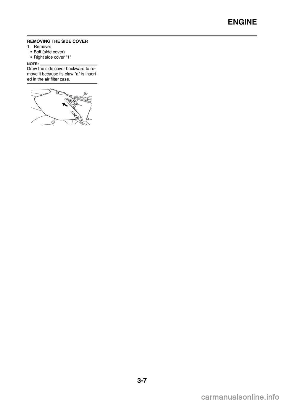
REMOVING THE SIDE COVER
1. Remove:
• Bolt (side cover)
• Right side cover "1"
Draw the side cover backward to re-
move it because its claw "a" is insert-
ed in the air filter case.
Page 66 of 224
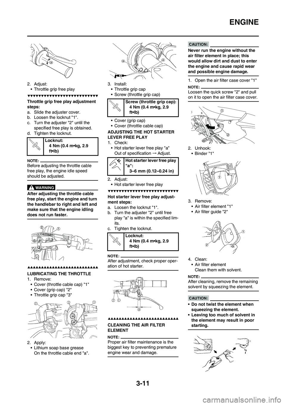
3-11
ENGINE
2. Adjust:
• Throttle grip free play
Throttle grip free play adjustment
steps:
a. Slide the adjuster cover.
b. Loosen the locknut "1".
c. Turn the adjuster "2" until the
specified free play is obtained.
d. Tighten the locknut.
Before adjusting the throttle cable
free play, the engine idle speed
should be adjusted.
After adjusting the throttle cable
free play, start the engine and turn
the handlebar to right and left and
make sure that the engine idling
does not run faster.
LUBRICATING THE THROTTLE
1. Remove:
• Cover (throttle cable cap) "1"
• Cover (grip cap) "2"
• Throttle grip cap "3"
2. Apply:
• Lithium soap base grease
On the throttle cable end "a".3. Install:
• Throttle grip cap
• Screw (throttle grip cap)
• Cover (grip cap)
• Cover (throttle cable cap)
ADJUSTING THE HOT STARTER
LEVER FREE PLAY
1. Check:
• Hot starter lever free play "a"
Out of specification→Adjust.
2. Adjust:
• Hot starter lever free play
Hot starter lever free play adjust-
ment steps:
a. Loosen the locknut "1".
b. Turn the adjuster "2" until free
play "a" is within the specified lim-
its.
c. Tighten the locknut.
After adjustment, check proper oper-
ation of hot starter.
CLEANING THE AIR FILTER
ELEMENT
Proper air filter maintenance is the
biggest key to preventing premature
engine wear and damage.
Never run the engine without the
air filter element in place; this
would allow dirt and dust to enter
the engine and cause rapid wear
and possible engine damage.
1. Open the air filter case cover "1"
Loosen the quick screw "2" and pull
on it to open the air filter case cover.
2. Unhook:
•Binder "1"
3. Remove:
• Air filter element "1"
• Air filter guide "2"
4. Clean:
• Air filter element
Clean them with solvent.
After cleaning, remove the remaining
solvent by squeezing the element.
• Do not twist the element when
squeezing the element.
• Leaving too much of solvent in
the element may result in poor
starting.
Locknut:
4 Nm (0.4 m•kg, 2.9
ft•lb)
Screw (throttle grip cap):
4 Nm (0.4 m•kg, 2.9
ft•lb)
Hot starter lever free play
"a":
3–6 mm (0.12–0.24 in)
Locknut:
4 Nm (0.4 m•kg, 2.9
ft•lb)
Page 67 of 224

3-12
ENGINE
5. Inspect:
• Air filter element
Damage→Replace.
6. Apply:
• Foam-air-filter oil or equivalent oil
to the element
• Squeeze out the excess oil. Ele-
ment should be wet but not drip-
ping.
• Wipe off the oil left on the element
surface using a clean dry cloth. (Ex-
cess oil in the element may ad-
versely affect engine starting.)
7. Install:
• Air filter guide "1"
• Align the projection "a" on filter
guide with the hole "b" in air filter el-
ement.
• Apply the lithium soap base grease
on the matching surface "c" on air
filter element.
8. Install:
• Air filter element "1"
Align the projection "a" on filter guide
with the hole "b" in air filter case.
9. Hook:
•Binder "1"
Hook the binder "1" so that it contacts
the filter guide projections "a".
CHECKING THE ENGINE OIL
LEVEL
1. Stand the machine on a level sur-
face.
• When checking the oil level make
sure that the machine is upright.
• Place the machine on a suitable
stand.
Never remove the oil tank cap just
after high speed operation. The
heated oil could spurt out. causing
danger. Wait until the oil cools
down to approximately 70°C
(158°F).
2. Idle the engine more than 3 min-
utes while keeping the machine
upright. Then stop the engine and
inspect the oil level.
3. Remove:
• Oil tank cap 1
4. Inspect:
• Oil level
Check that the engine oil is above
the level mark "a" and that the oil
does not come out when the
check bolt "1" is removed.
Below the level mark "a"→Add oil
through the filler cap hole until it is
above the level mark "a".
Oil comes out at the check bolt→
Drain the oil until it stops coming
out.
When inspecting the oil level, do not
screw the oil level gauge into the oil
tank. Insert the gauge lightly.
(For CDN)
• Do not add any chemical addi-
tives. Engine oil also lubricates
the clutch and additives could
cause clutch slippage.
• Do not allow foreign material to
enter the crankcase.
(Except for CDN)
Recommended oil:
Yamalube 4,
SAE10W30 or
SAE20W40
Yamalube 4-R,
SAE10W50
API service SG type or
higher, JASO standard
MA
Recommended oil:
SAE10W30,
SAE10W40,
SAE15W40, SAE20W40
or SAE20W50
API service SG type or
higher, JASO standard
MA