YAMAHA WR 450F 2009 Owners Manual
Manufacturer: YAMAHA, Model Year: 2009, Model line: WR 450F, Model: YAMAHA WR 450F 2009Pages: 226, PDF Size: 14.26 MB
Page 131 of 226
5-33
CLUTCH
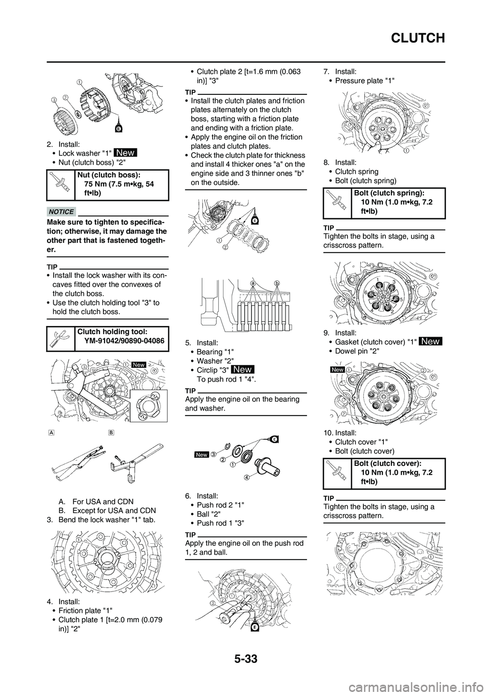
2. Install:
• Lock washer "1"
• Nut (clutch boss) "2"
Make sure to tighten to specifica-
tion; otherwise, it may damage the
other part that is fastened togeth-
er.
• Install the lock washer with its con-
caves fitted over the convexes of
the clutch boss.
• Use the clutch holding tool "3" to
hold the clutch boss.
A. For USA and CDN
B. Except for USA and CDN
3. Bend the lock washer "1" tab.
4. Install:
• Friction plate "1"
• Clutch plate 1 [t=2.0 mm (0.079
in)] "2"• Clutch plate 2 [t=1.6 mm (0.063
in)] "3"
• Install the clutch plates and friction
plates alternately on the clutch
boss, starting with a friction plate
and ending with a friction plate.
• Apply the engine oil on the friction
plates and clutch plates.
• Check the clutch plate for thickness
and install 4 thicker ones "a" on the
engine side and 3 thinner ones "b"
on the outside.
5. Install:
•Bearing "1"
• Washer "2"
• Circlip "3"
To push rod 1 "4".
Apply the engine oil on the bearing
and washer.
6. Install:
• Push rod 2 "1"
• Ball "2"
• Push rod 1 "3"
Apply the engine oil on the push rod
1, 2 and ball.
7. Install:
• Pressure plate "1"
8. Install:
• Clutch spring
• Bolt (clutch spring)
Tighten the bolts in stage, using a
crisscross pattern.
9. Install:
• Gasket (clutch cover) "1"
• Dowel pin "2"
10. Install:
• Clutch cover "1"
• Bolt (clutch cover)
Tighten the bolts in stage, using a
crisscross pattern.
Nut (clutch boss):
75 Nm (7.5 m•kg, 54
ft•lb)
Clutch holding tool:
YM-91042/90890-04086
Bolt (clutch spring):
10 Nm (1.0 m•kg, 7.2
ft•lb)
Bolt (clutch cover):
10 Nm (1.0 m•kg, 7.2
ft•lb)
Page 132 of 226
5-34
OIL FILTER ELEMENT AND WATER PUMP
OIL FILTER ELEMENT AND WATER PUMP
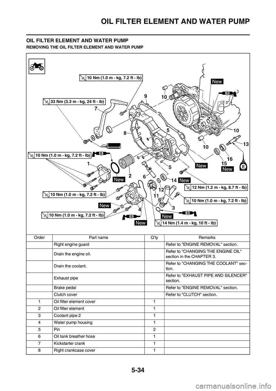
REMOVING THE OIL FILTER ELEMENT AND WATER PUMP
Order Part name Q'ty Remarks
Right engine guard Refer to "ENGINE REMOVAL" section.
Drain the engine oil. Refer to "CHANGING THE ENGINE OIL"
section in the CHAPTER 3.
Drain the coolant. Refer to "CHANGING THE COOLANT" sec-
tion.
Exhaust pipe Refer to "EXHAUST PIPE AND SILENCER"
section.
Brake pedal Refer to "ENGINE REMOVAL" section.
Clutch cover Refer to "CLUTCH" section.
1 Oil filter element cover 1
2 Oil filter element 1
3 Coolant pipe 2 1
4 Water pump housing 1
5Pin 2
6 Oil tank breather hose 1
7 Kickstarter crank 1
8 Right crankcase cover 1
10 Nm (1.0 m kg, 7.2 ft lb)
10 Nm (1.0 m kg, 7.2 ft lb)
10 Nm (1.0 m kg, 7.2 ft lb)
10 Nm (1.0 m kg, 7.2 ft lb)
10 Nm (1.0 m kg, 7.2 ft lb)
33 Nm (3.3 m kg, 24 ft lb)
14 Nm (1.4 m kg, 10 ft lb)
12 Nm (1.2 m kg, 8.7 ft lb)
Page 133 of 226
5-35
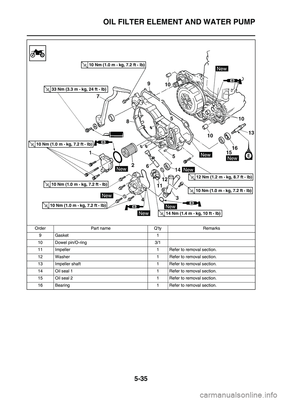
OIL FILTER ELEMENT AND WATER PUMP
9 Gasket 1
10 Dowel pin/O-ring 3/1
11 Impeller 1 Refer to removal section.
12 Washer 1 Refer to removal section.
13 Impeller shaft 1 Refer to removal section.
14 Oil seal 1 1 Refer to removal section.
15 Oil seal 2 1 Refer to removal section.
16 Bearing 1 Refer to removal section. Order Part name Q'ty Remarks
10 Nm (1.0 m kg, 7.2 ft lb)
10 Nm (1.0 m kg, 7.2 ft lb)
10 Nm (1.0 m kg, 7.2 ft lb)
10 Nm (1.0 m kg, 7.2 ft lb)
10 Nm (1.0 m kg, 7.2 ft lb)
33 Nm (3.3 m kg, 24 ft lb)
14 Nm (1.4 m kg, 10 ft lb)
12 Nm (1.2 m kg, 8.7 ft lb)
Page 134 of 226
5-36
OIL FILTER ELEMENT AND WATER PUMP
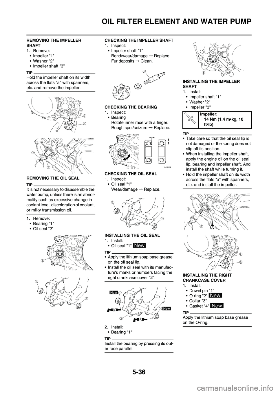
REMOVING THE IMPELLER
SHAFT
1. Remove:
• Impeller "1"
• Washer "2"
• Impeller shaft "3"
Hold the impeller shaft on its width
across the flats "a" with spanners,
etc. and remove the impeller.
REMOVING THE OIL SEAL
It is not necessary to disassemble the
water pump, unless there is an abnor-
mality such as excessive change in
coolant level, discoloration of coolant,
or milky transmission oil.
1. Remove:
• Bearing "1"
• Oil seal "2"CHECKING THE IMPELLER SHAFT
1. Inspect:
• Impeller shaft "1"
Bend/wear/damage→Replace.
Fur deposits→Clean.
CHECKING THE BEARING
1. Inspect:
•Bearing
Rotate inner race with a finger.
Rough spot/seizure→Replace.
CHECKING THE OIL SEAL
1. Inspect:
• Oil seal "1"
Wear/damage→Replace.
INSTALLING THE OIL SEAL
1. Install:
• Oil seal "1"
• Apply the lithium soap base grease
on the oil seal lip.
• Install the oil seal with its manufac-
ture's marks or numbers facing the
right crankcase cover "2".
2. Install:
•Bearing "1"
Install the bearing by pressing its out-
er race parallel.
INSTALLING THE IMPELLER
SHAFT
1. Install:
• Impeller shaft "1"
• Washer "2"
• Impeller "3"
• Take care so that the oil seal lip is
not damaged or the spring does not
slip off its position.
• When installing the impeller shaft,
apply the engine oil on the oil seal
lip, bearing and impeller shaft. And
install the shaft while turning it.
• Hold the impeller shaft on its width
across the flats "a" with spanners,
etc. and install the impeller.
INSTALLING THE RIGHT
CRANKCASE COVER
1. Install:
• Dowel pin "1"
• O-ring "2"
•Collar "3"
• Gasket "4"
Apply the lithium soap base grease
on the O-ring.
Impeller:
14 Nm (1.4 m•kg, 10
ft•lb)
Page 135 of 226
5-37
OIL FILTER ELEMENT AND WATER PUMP
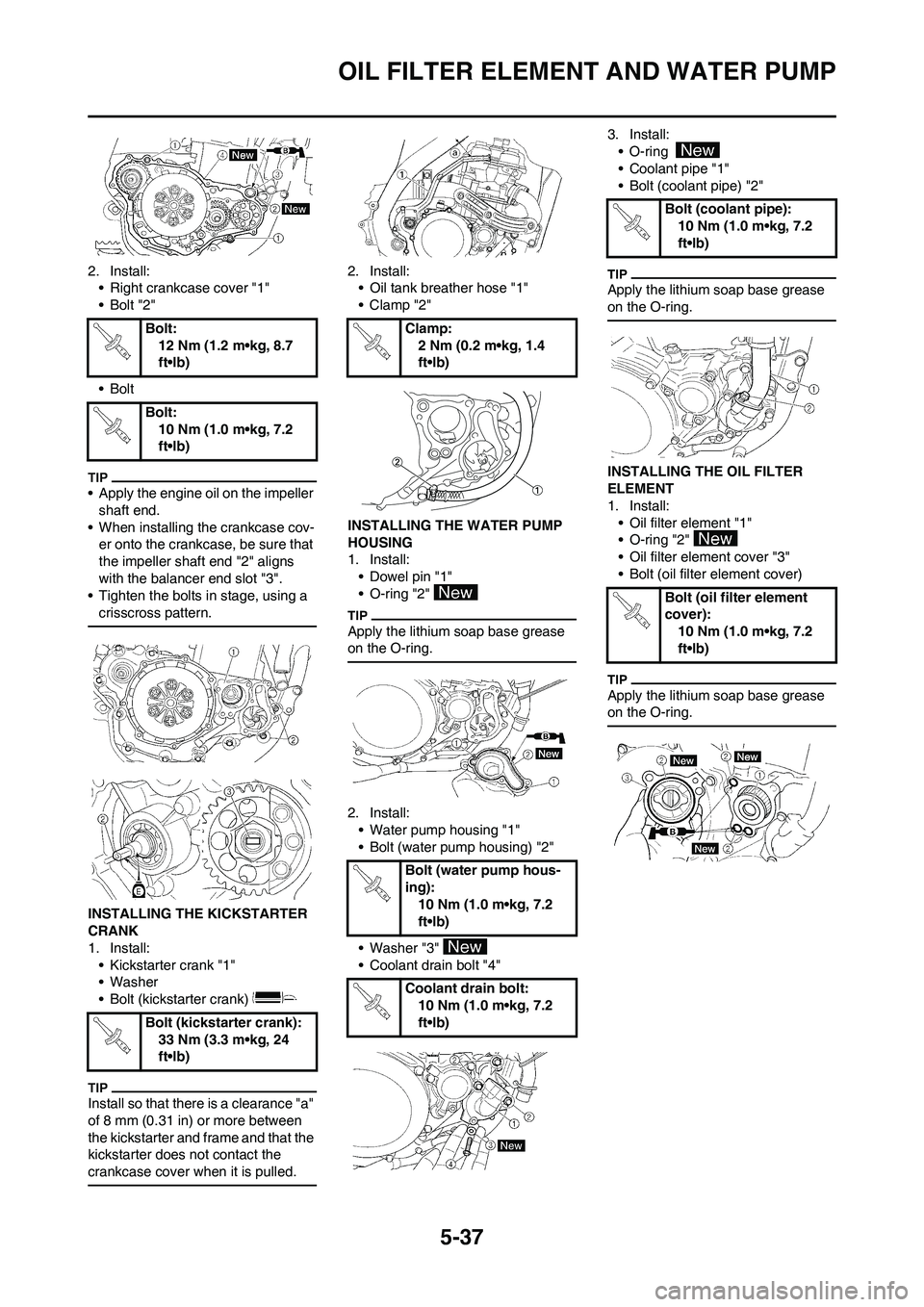
2. Install:
• Right crankcase cover "1"
•Bolt "2"
•Bolt
• Apply the engine oil on the impeller
shaft end.
• When installing the crankcase cov-
er onto the crankcase, be sure that
the impeller shaft end "2" aligns
with the balancer end slot "3".
• Tighten the bolts in stage, using a
crisscross pattern.
INSTALLING THE KICKSTARTER
CRANK
1. Install:
• Kickstarter crank "1"
• Washer
• Bolt (kickstarter crank)
Install so that there is a clearance "a"
of 8 mm (0.31 in) or more between
the kickstarter and frame and that the
kickstarter does not contact the
crankcase cover when it is pulled.
2. Install:
• Oil tank breather hose "1"
•Clamp "2"
INSTALLING THE WATER PUMP
HOUSING
1. Install:
• Dowel pin "1"
• O-ring "2"
Apply the lithium soap base grease
on the O-ring.
2. Install:
• Water pump housing "1"
• Bolt (water pump housing) "2"
• Washer "3"
• Coolant drain bolt "4"3. Install:
• O-ring
• Coolant pipe "1"
• Bolt (coolant pipe) "2"
Apply the lithium soap base grease
on the O-ring.
INSTALLING THE OIL FILTER
ELEMENT
1. Install:
• Oil filter element "1"
• O-ring "2"
• Oil filter element cover "3"
• Bolt (oil filter element cover)
Apply the lithium soap base grease
on the O-ring.
Bolt:
12 Nm (1.2 m•kg, 8.7
ft•lb)
Bolt:
10 Nm (1.0 m•kg, 7.2
ft•lb)
Bolt (kickstarter crank):
33 Nm (3.3 m•kg, 24
ft•lb)Clamp:
2 Nm (0.2 m•kg, 1.4
ft•lb)
Bolt (water pump hous-
ing):
10 Nm (1.0 m•kg, 7.2
ft•lb)
Coolant drain bolt:
10 Nm (1.0 m•kg, 7.2
ft•lb)
Bolt (coolant pipe):
10 Nm (1.0 m•kg, 7.2
ft•lb)
Bolt (oil filter element
cover):
10 Nm (1.0 m•kg, 7.2
ft•lb)
Page 136 of 226
5-38
BALANCER
BALANCER
REMOVING THE BALANCER
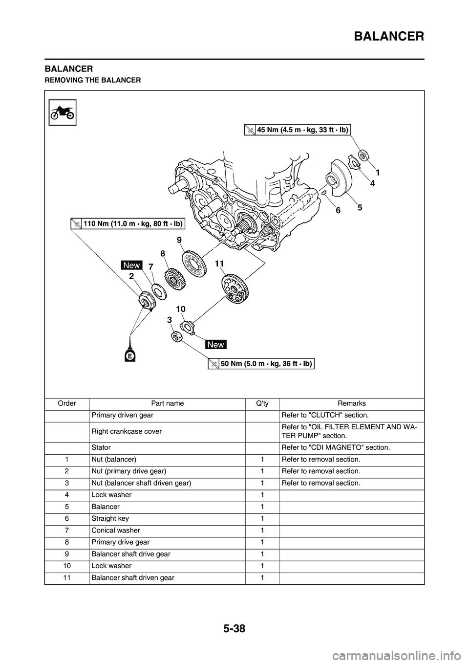
Order Part name Q'ty Remarks
Primary driven gear Refer to "CLUTCH" section.
Right crankcase cover Refer to "OIL FILTER ELEMENT AND WA-
TER PUMP" section.
Stator Refer to "CDI MAGNETO" section.
1 Nut (balancer) 1 Refer to removal section.
2 Nut (primary drive gear) 1 Refer to removal section.
3 Nut (balancer shaft driven gear) 1 Refer to removal section.
4 Lock washer 1
5 Balancer 1
6 Straight key 1
7 Conical washer 1
8 Primary drive gear 1
9 Balancer shaft drive gear 1
10 Lock washer 1
11 Balancer shaft driven gear 1
Page 137 of 226
5-39
BALANCER
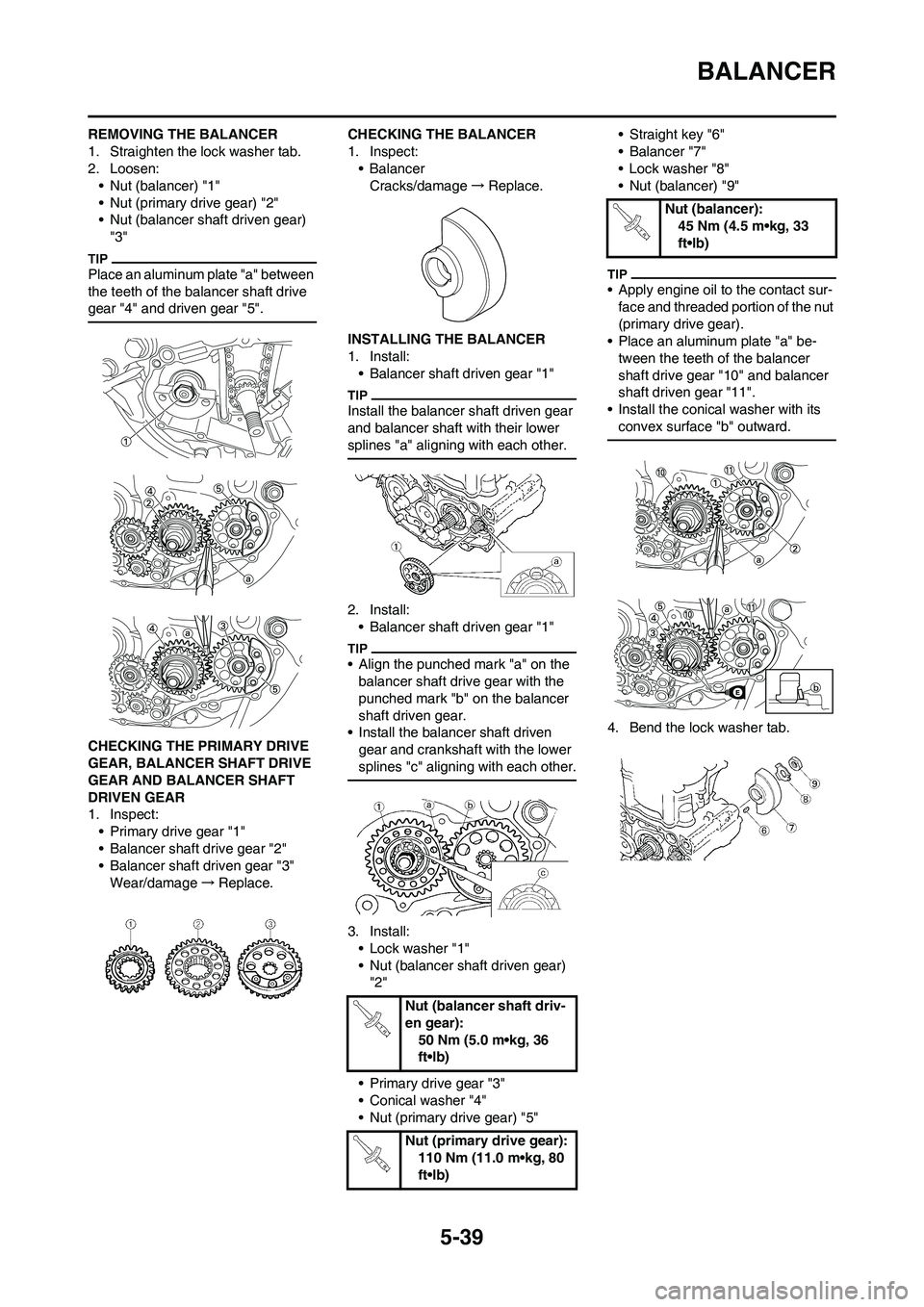
REMOVING THE BALANCER
1. Straighten the lock washer tab.
2. Loosen:
• Nut (balancer) "1"
• Nut (primary drive gear) "2"
• Nut (balancer shaft driven gear)
"3"
Place an aluminum plate "a" between
the teeth of the balancer shaft drive
gear "4" and driven gear "5".
CHECKING THE PRIMARY DRIVE
GEAR, BALANCER SHAFT DRIVE
GEAR AND BALANCER SHAFT
DRIVEN GEAR
1. Inspect:
• Primary drive gear "1"
• Balancer shaft drive gear "2"
• Balancer shaft driven gear "3"
Wear/damage→Replace.CHECKING THE BALANCER
1. Inspect:
• Balancer
Cracks/damage→Replace.
INSTALLING THE BALANCER
1. Install:
• Balancer shaft driven gear "1"
Install the balancer shaft driven gear
and balancer shaft with their lower
splines "a" aligning with each other.
2. Install:
• Balancer shaft driven gear "1"
• Align the punched mark "a" on the
balancer shaft drive gear with the
punched mark "b" on the balancer
shaft driven gear.
• Install the balancer shaft driven
gear and crankshaft with the lower
splines "c" aligning with each other.
3. Install:
• Lock washer "1"
• Nut (balancer shaft driven gear)
"2"
• Primary drive gear "3"
• Conical washer "4"
• Nut (primary drive gear) "5"• Straight key "6"
• Balancer "7"
• Lock washer "8"
• Nut (balancer) "9"
• Apply engine oil to the contact sur-
face and threaded portion of the nut
(primary drive gear).
• Place an aluminum plate "a" be-
tween the teeth of the balancer
shaft drive gear "10" and balancer
shaft driven gear "11".
• Install the conical washer with its
convex surface "b" outward.
4. Bend the lock washer tab.
Nut (balancer shaft driv-
en gear):
50 Nm (5.0 m•kg, 36
ft•lb)
Nut (primary drive gear):
110 Nm (11.0 m•kg, 80
ft•lb)
Nut (balancer):
45 Nm (4.5 m•kg, 33
ft•lb)
Page 138 of 226
5-40
OIL PUMP
OIL PUMP
REMOVING THE OIL PUMP
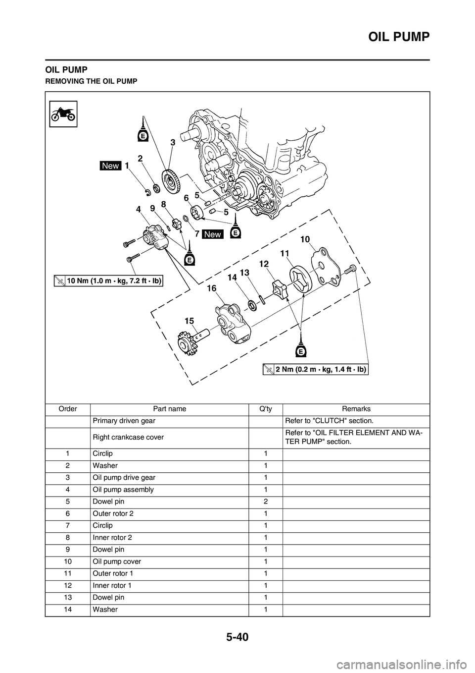
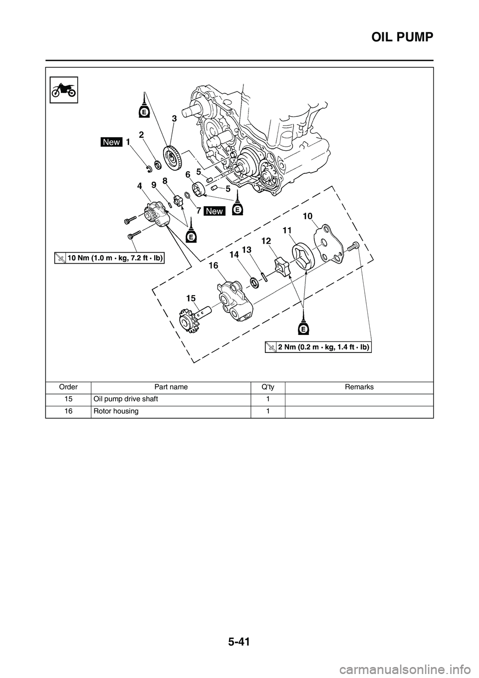
Order Part name Q'ty Remarks
Primary driven gear Refer to "CLUTCH" section.
Right crankcase coverRefer to "OIL FILTER ELEMENT AND WA-
TER PUMP" section.
1 Circlip 1
2 Washer 1
3 Oil pump drive gear 1
4 Oil pump assembly 1
5 Dowel pin 2
6 Outer rotor 2 1
7 Circlip 1
8 Inner rotor 2 1
9 Dowel pin 1
10 Oil pump cover 1
11 Outer rotor 1 1
12 Inner rotor 1 1
13 Dowel pin 1
14 Washer 1
Page 139 of 226
5-41
OIL PUMP
15 Oil pump drive shaft 1
16 Rotor housing 1 Order Part name Q'ty Remarks
Page 140 of 226
5-42
OIL PUMP
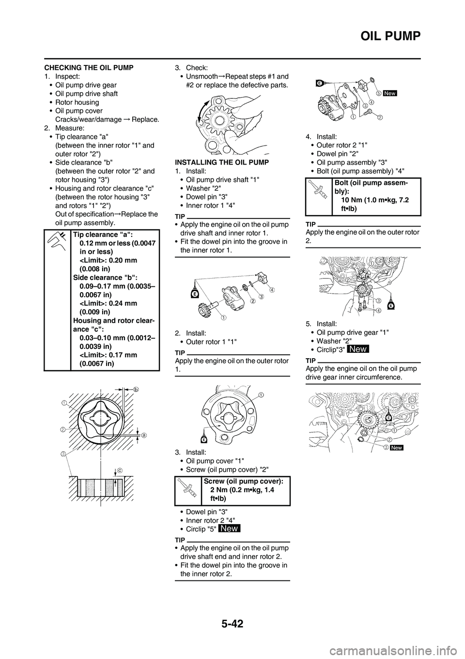
CHECKING THE OIL PUMP
1. Inspect:
• Oil pump drive gear
• Oil pump drive shaft
• Rotor housing
• Oil pump cover
Cracks/wear/damage→Replace.
2. Measure:
• Tip clearance "a"
(between the inner rotor "1" and
outer rotor "2")
• Side clearance "b"
(between the outer rotor "2" and
rotor housing "3")
• Housing and rotor clearance "c"
(between the rotor housing "3"
and rotors "1" "2")
Out of specification→Replace the
oil pump assembly.3. Check:
• Unsmooth→Repeat steps #1 and
#2 or replace the defective parts.
INSTALLING THE OIL PUMP
1. Install:
• Oil pump drive shaft "1"
• Washer "2"
• Dowel pin "3"
• Inner rotor 1 "4"
• Apply the engine oil on the oil pump
drive shaft and inner rotor 1.
• Fit the dowel pin into the groove in
the inner rotor 1.
2. Install:
• Outer rotor 1 "1"
Apply the engine oil on the outer rotor
1.
3. Install:
• Oil pump cover "1"
• Screw (oil pump cover) "2"
• Dowel pin "3"
• Inner rotor 2 "4"
• Circlip "5"
• Apply the engine oil on the oil pump
drive shaft end and inner rotor 2.
• Fit the dowel pin into the groove in
the inner rotor 2.
4. Install:
• Outer rotor 2 "1"
• Dowel pin "2"
• Oil pump assembly "3"
• Bolt (oil pump assembly) "4"
Apply the engine oil on the outer rotor
2.
5. Install:
• Oil pump drive gear "1"
• Washer "2"
• Circlip"3"
Apply the engine oil on the oil pump
drive gear inner circumference.
Tip clearance "a":
0.12 mm or less (0.0047
in or less)
(0.008 in)
Side clearance "b":
0.09–0.17 mm (0.0035–
0.0067 in)
(0.009 in)
Housing and rotor clear-
ance "c":
0.03–0.10 mm (0.0012–
0.0039 in)
(0.0067 in)
Screw (oil pump cover):
2 Nm (0.2 m•kg, 1.4
ft•lb)
Bolt (oil pump assem-
bly):
10 Nm (1.0 m•kg, 7.2
ft•lb)