YAMAHA WR 450F 2009 Owners Manual
Manufacturer: YAMAHA, Model Year: 2009, Model line: WR 450F, Model: YAMAHA WR 450F 2009Pages: 226, PDF Size: 14.26 MB
Page 151 of 226
5-53
ENGINE REMOVAL
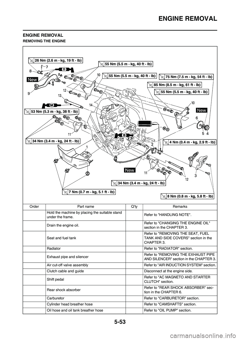
ENGINE REMOVAL
REMOVING THE ENGINE
Order Part name Q'ty Remarks
Hold the machine by placing the suitable stand
under the frame.Refer to "HANDLING NOTE".
Drain the engine oil.Refer to "CHANGING THE ENGINE OIL"
section in the CHAPTER 3.
Seat and fuel tank Refer to "REMOVING THE SEAT, FUEL
TANK AND SIDE COVERS" section in the
CHAPTER 3.
Radiator Refer to "RADIATOR" section.
Exhaust pipe and silencer Refer to "REMOVING THE EXHAUST PIPE
AND SILENCER" section in the CHAPTER 3.
Air cut-off valve assembly Refer to "AIR INDUCTION SYSTEM" section.
Clutch cable and guide Disconnect at the engine side.
Shift pedalRefer to "AC MAGNETO AND STARTER
CLUTCH" section.
Rear shock absorberRefer to "REAR SHOCK ABSORBER" sec-
tion in the CHAPTER 6.
Carburetor Refer to "CARBURETOR" section.
Cylinder head breather hose Refer to "CAMSHAFTS" section.
Oil hose and oil tank breather hose Refer to "OIL PUMP" section.
Page 152 of 226
5-54
ENGINE REMOVAL
Ignition coil
Disconnect the AC magneto lead.
Disconnect the starter motor lead.Refer to "ELECTRIC STARTING SYSTEM"
section in the CHAPTER 7.
Negative battery lead Disconnect at the engine side.
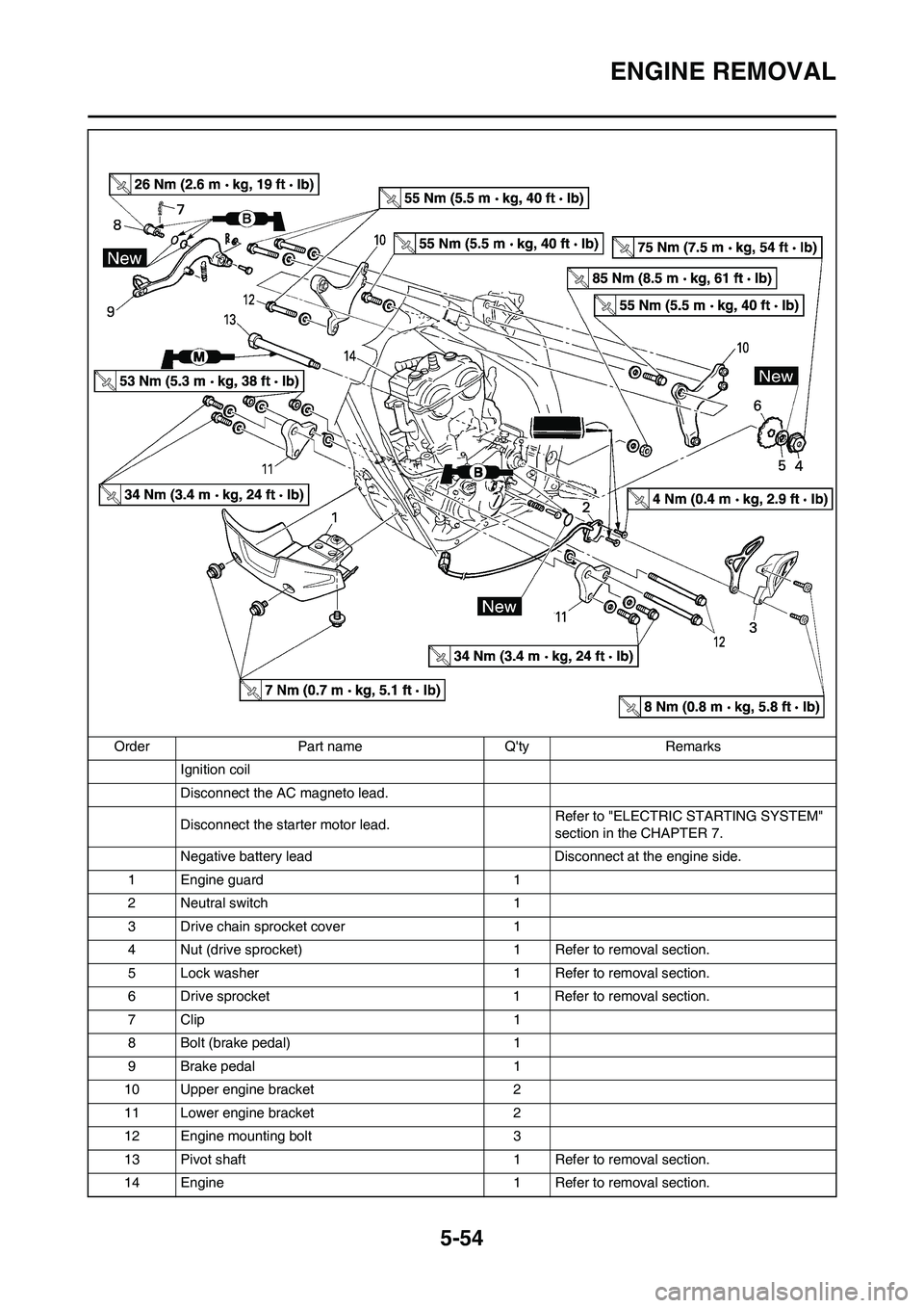
1 Engine guard 1
2 Neutral switch 1
3 Drive chain sprocket cover 1
4 Nut (drive sprocket) 1 Refer to removal section.
5 Lock washer 1 Refer to removal section.
6 Drive sprocket 1 Refer to removal section.
7Clip 1
8 Bolt (brake pedal) 1
9 Brake pedal 1
10 Upper engine bracket 2
11 Lower engine bracket 2
12 Engine mounting bolt 3
13 Pivot shaft 1 Refer to removal section.
14 Engine 1 Refer to removal section. Order Part name Q'ty Remarks
Page 153 of 226
5-55
ENGINE REMOVAL
HANDLING NOTE
Support the machine securely so
there is no danger of it falling over.
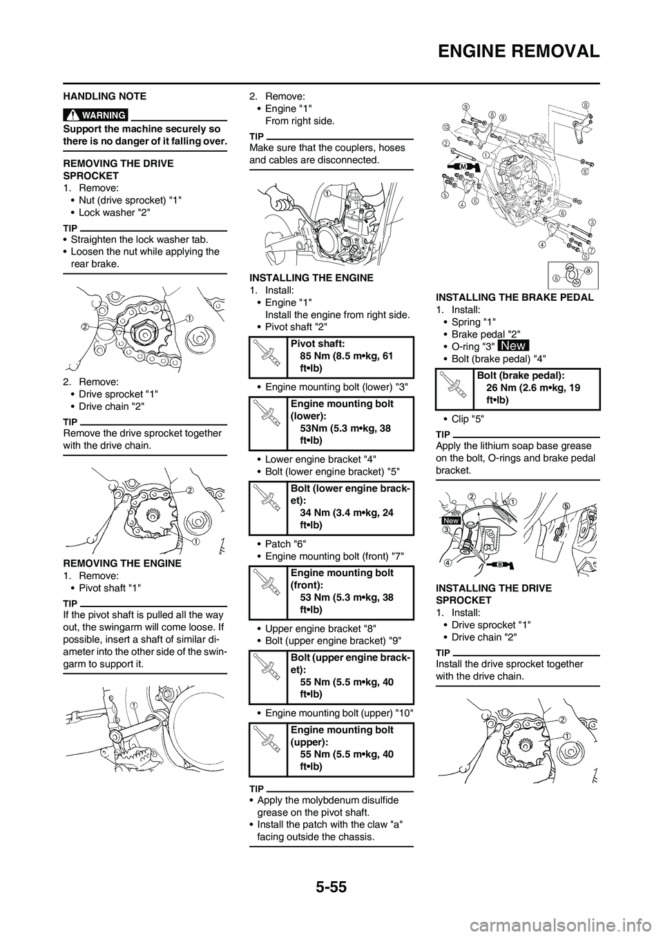
REMOVING THE DRIVE
SPROCKET
1. Remove:
• Nut (drive sprocket) "1"
• Lock washer "2"
• Straighten the lock washer tab.
• Loosen the nut while applying the
rear brake.
2. Remove:
• Drive sprocket "1"
• Drive chain "2"
Remove the drive sprocket together
with the drive chain.
REMOVING THE ENGINE
1. Remove:
• Pivot shaft "1"
If the pivot shaft is pulled all the way
out, the swingarm will come loose. If
possible, insert a shaft of similar di-
ameter into the other side of the swin-
garm to support it.
2. Remove:
• Engine "1"
From right side.
Make sure that the couplers, hoses
and cables are disconnected.
INSTALLING THE ENGINE
1. Install:
• Engine "1"
Install the engine from right side.
• Pivot shaft "2"
• Engine mounting bolt (lower) "3"
• Lower engine bracket "4"
• Bolt (lower engine bracket) "5"
• Patch "6"
• Engine mounting bolt (front) "7"
• Upper engine bracket "8"
• Bolt (upper engine bracket) "9"
• Engine mounting bolt (upper) "10"
• Apply the molybdenum disulfide
grease on the pivot shaft.
• Install the patch with the claw "a"
facing outside the chassis.
INSTALLING THE BRAKE PEDAL
1. Install:
• Spring "1"
• Brake pedal "2"
• O-ring "3"
• Bolt (brake pedal) "4"
• Clip "5"
Apply the lithium soap base grease
on the bolt, O-rings and brake pedal
bracket.
INSTALLING THE DRIVE
SPROCKET
1. Install:
• Drive sprocket "1"
• Drive chain "2"
Install the drive sprocket together
with the drive chain.
Pivot shaft:
85 Nm (8.5 m•kg, 61
ft•lb)
Engine mounting bolt
(lower):
53Nm (5.3 m•kg, 38
ft•lb)
Bolt (lower engine brack-
et):
34 Nm (3.4 m•kg, 24
ft•lb)
Engine mounting bolt
(front):
53 Nm (5.3 m•kg, 38
ft•lb)
Bolt (upper engine brack-
et):
55 Nm (5.5 m•kg, 40
ft•lb)
Engine mounting bolt
(upper):
55 Nm (5.5 m•kg, 40
ft•lb)
Bolt (brake pedal):
26 Nm (2.6 m•kg, 19
ft•lb)
Page 154 of 226
5-56
ENGINE REMOVAL
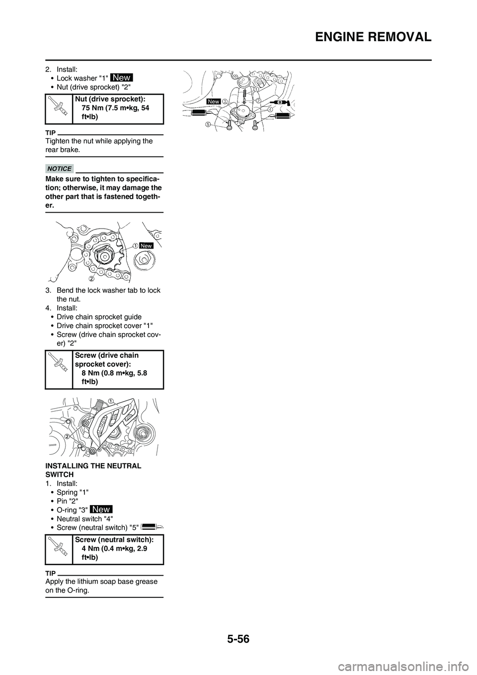
2. Install:
• Lock washer "1"
• Nut (drive sprocket) "2"
Tighten the nut while applying the
rear brake.
Make sure to tighten to specifica-
tion; otherwise, it may damage the
other part that is fastened togeth-
er.
3. Bend the lock washer tab to lock
the nut.
4. Install:
• Drive chain sprocket guide
• Drive chain sprocket cover "1"
• Screw (drive chain sprocket cov-
er) "2"
INSTALLING THE NEUTRAL
SWITCH
1. Install:
• Spring "1"
•Pin "2"
• O-ring "3"
• Neutral switch "4"
• Screw (neutral switch) "5"
Apply the lithium soap base grease
on the O-ring.
Nut (drive sprocket):
75 Nm (7.5 m•kg, 54
ft•lb)
Screw (drive chain
sprocket cover):
8 Nm (0.8 m•kg, 5.8
ft•lb)
Screw (neutral switch):
4 Nm (0.4 m•kg, 2.9
ft•lb)
Page 155 of 226
5-57
CRANKCASE AND CRANKSHAFT
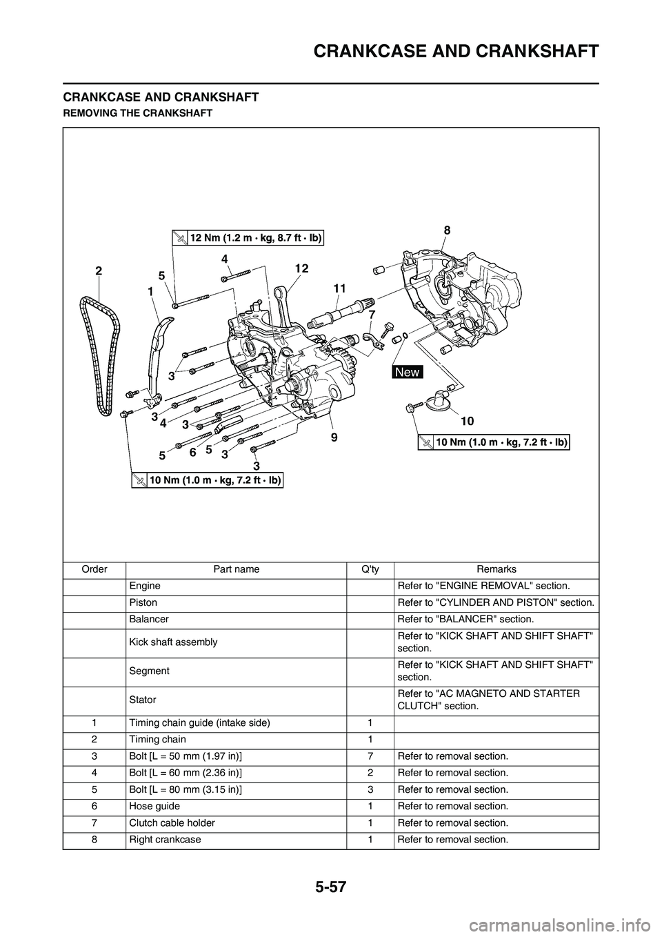
CRANKCASE AND CRANKSHAFT
REMOVING THE CRANKSHAFT
Order Part name Q'ty Remarks
Engine Refer to "ENGINE REMOVAL" section.
Piston Refer to "CYLINDER AND PISTON" section.
Balancer Refer to "BALANCER" section.
Kick shaft assemblyRefer to "KICK SHAFT AND SHIFT SHAFT"
section.
SegmentRefer to "KICK SHAFT AND SHIFT SHAFT"
section.
StatorRefer to "AC MAGNETO AND STARTER
CLUTCH" section.
1 Timing chain guide (intake side) 1
2 Timing chain 1
3 Bolt [L = 50 mm (1.97 in)] 7 Refer to removal section.
4 Bolt [L = 60 mm (2.36 in)] 2 Refer to removal section.
5 Bolt [L = 80 mm (3.15 in)] 3 Refer to removal section.
6 Hose guide 1 Refer to removal section.
7 Clutch cable holder 1 Refer to removal section.
8 Right crankcase 1 Refer to removal section.
Page 156 of 226
5-58
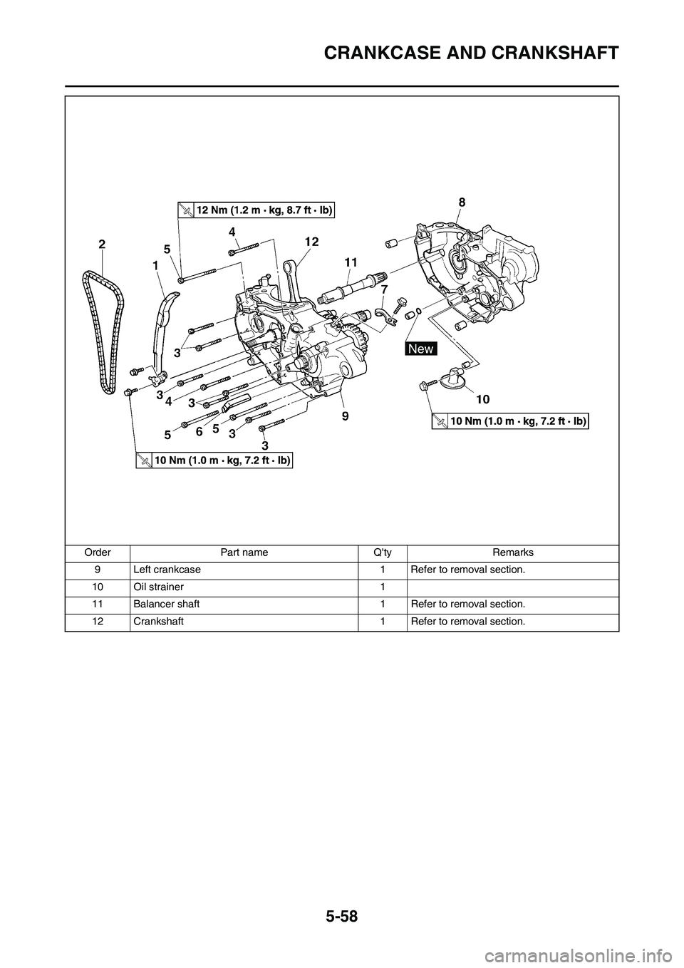
CRANKCASE AND CRANKSHAFT
9 Left crankcase 1 Refer to removal section.
10 Oil strainer 1
11 Balancer shaft 1 Refer to removal section.
12 Crankshaft 1 Refer to removal section. Order Part name Q'ty Remarks
Page 157 of 226
5-59
CRANKCASE AND CRANKSHAFT
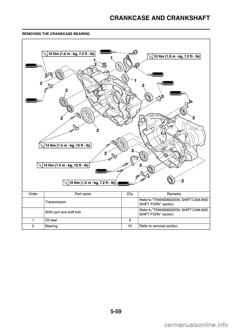
REMOVING THE CRANKCASE BEARING
Order Part name Q'ty Remarks
TransmissionRefer to "TRANSMISSION, SHIFT CAM AND
SHIFT FORK" section.
Shift cam and shift fork Refer to "TRANSMISSION, SHIFT CAM AND
SHIFT FORK" section.
1 Oil seal 3
2 Bearing 10 Refer to removal section.
Page 158 of 226
5-60
CRANKCASE AND CRANKSHAFT
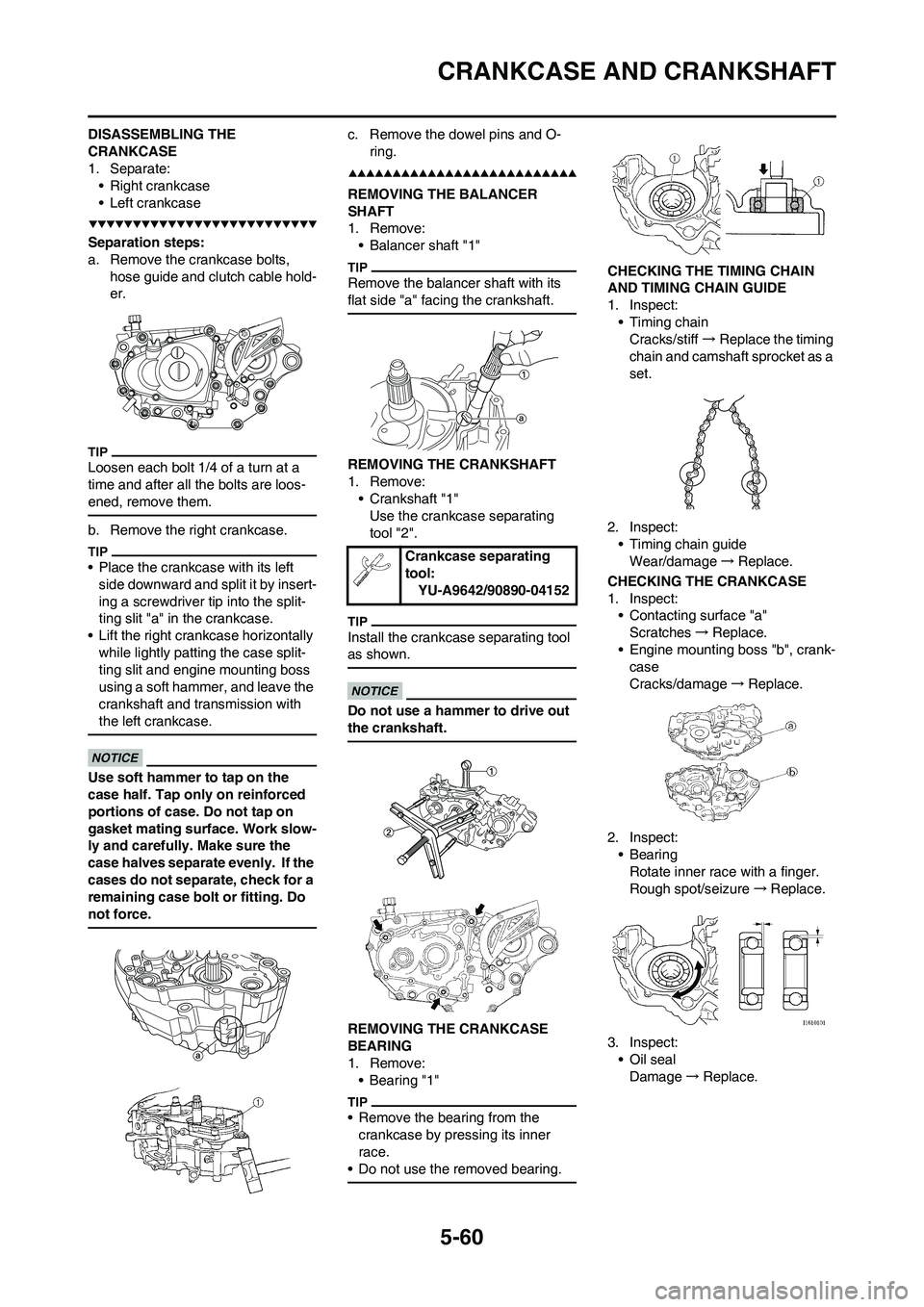
DISASSEMBLING THE
CRANKCASE
1. Separate:
• Right crankcase
• Left crankcase
Separation steps:
a. Remove the crankcase bolts,
hose guide and clutch cable hold-
er.
Loosen each bolt 1/4 of a turn at a
time and after all the bolts are loos-
ened, remove them.
b. Remove the right crankcase.
• Place the crankcase with its left
side downward and split it by insert-
ing a screwdriver tip into the split-
ting slit "a" in the crankcase.
• Lift the right crankcase horizontally
while lightly patting the case split-
ting slit and engine mounting boss
using a soft hammer, and leave the
crankshaft and transmission with
the left crankcase.
Use soft hammer to tap on the
case half. Tap only on reinforced
portions of case. Do not tap on
gasket mating surface. Work slow-
ly and carefully. Make sure the
case halves separate evenly. If the
cases do not separate, check for a
remaining case bolt or fitting. Do
not force.
c. Remove the dowel pins and O-
ring.
REMOVING THE BALANCER
SHAFT
1. Remove:
• Balancer shaft "1"
Remove the balancer shaft with its
flat side "a" facing the crankshaft.
REMOVING THE CRANKSHAFT
1. Remove:
• Crankshaft "1"
Use the crankcase separating
tool "2".
Install the crankcase separating tool
as shown.
Do not use a hammer to drive out
the crankshaft.
REMOVING THE CRANKCASE
BEARING
1. Remove:
•Bearing "1"
• Remove the bearing from the
crankcase by pressing its inner
race.
• Do not use the removed bearing.
CHECKING THE TIMING CHAIN
AND TIMING CHAIN GUIDE
1. Inspect:
• Timing chain
Cracks/stiff→Replace the timing
chain and camshaft sprocket as a
set.
2. Inspect:
• Timing chain guide
Wear/damage→Replace.
CHECKING THE CRANKCASE
1. Inspect:
• Contacting surface "a"
Scratches→Replace.
• Engine mounting boss "b", crank-
case
Cracks/damage→Replace.
2. Inspect:
• Bearing
Rotate inner race with a finger.
Rough spot/seizure→Replace.
3. Inspect:
• Oil seal
Damage→Replace.
Crankcase separating
tool:
YU-A9642/90890-04152
Page 159 of 226
5-61
CRANKCASE AND CRANKSHAFT
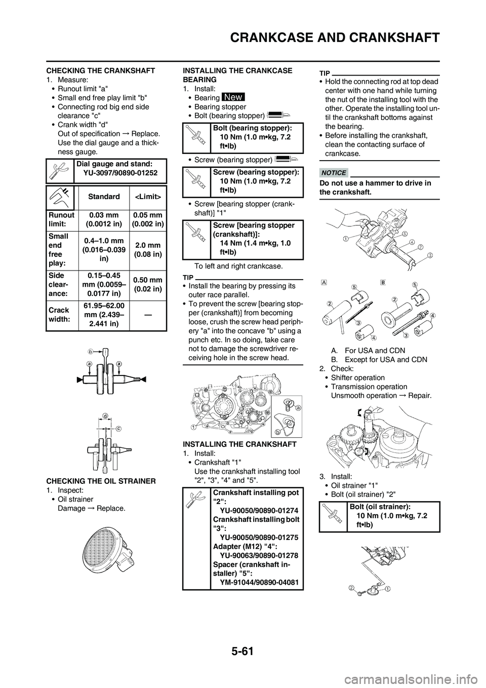
CHECKING THE CRANKSHAFT
1. Measure:
• Runout limit "a"
• Small end free play limit "b"
• Connecting rod big end side
clearance "c"
• Crank width "d"
Out of specification→Replace.
Use the dial gauge and a thick-
ness gauge.
CHECKING THE OIL STRAINER
1. Inspect:
• Oil strainer
Damage→Replace.INSTALLING THE CRANKCASE
BEARING
1. Install:
•Bearing
• Bearing stopper
• Bolt (bearing stopper)
• Screw (bearing stopper)
• Screw [bearing stopper (crank-
shaft)] "1"
To left and right crankcase.
• Install the bearing by pressing its
outer race parallel.
• To prevent the screw [bearing stop-
per (crankshaft)] from becoming
loose, crush the screw head periph-
ery "a" into the concave "b" using a
punch etc. In so doing, take care
not to damage the screwdriver re-
ceiving hole in the screw head.
INSTALLING THE CRANKSHAFT
1. Install:
• Crankshaft "1"
Use the crankshaft installing tool
"2", "3", "4" and "5".
• Hold the connecting rod at top dead
center with one hand while turning
the nut of the installing tool with the
other. Operate the installing tool un-
til the crankshaft bottoms against
the bearing.
• Before installing the crankshaft,
clean the contacting surface of
crankcase.
Do not use a hammer to drive in
the crankshaft.
A. For USA and CDN
B. Except for USA and CDN
2. Check:
• Shifter operation
• Transmission operation
Unsmooth operation→Repair.
3. Install:
• Oil strainer "1"
• Bolt (oil strainer) "2" Dial gauge and stand:
YU-3097/90890-01252
Standard
Runout
limit:0.03 mm
(0.0012 in)0.05 mm
(0.002 in)
Small
end
free
play:0.4–1.0 mm
(0.016–0.039
in)2.0 mm
(0.08 in)
Side
clear-
ance:0.15–0.45
mm (0.0059–
0.0177 in)0.50 mm
(0.02 in)
Crack
width:61.95–62.00
mm (2.439–
2.441 in)—
Bolt (bearing stopper):
10 Nm (1.0 m•kg, 7.2
ft•lb)
Screw (bearing stopper):
10 Nm (1.0 m•kg, 7.2
ft•lb)
Screw [bearing stopper
(crankshaft)]:
14 Nm (1.4 m•kg, 1.0
ft•lb)
Crankshaft installing pot
"2":
YU-90050/90890-01274
Crankshaft installing bolt
"3":
YU-90050/90890-01275
Adapter (M12) "4":
YU-90063/90890-01278
Spacer (crankshaft in-
staller) "5":
YM-91044/90890-04081
Bolt (oil strainer):
10 Nm (1.0 m•kg, 7.2
ft•lb)
Page 160 of 226
5-62
CRANKCASE AND CRANKSHAFT
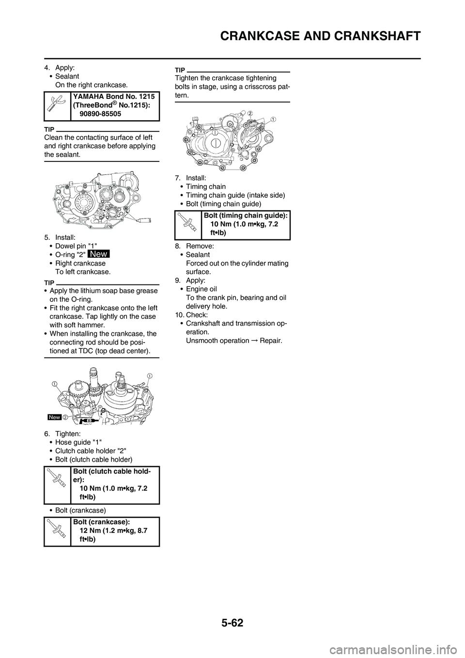
4. Apply:
• Sealant
On the right crankcase.
Clean the contacting surface of left
and right crankcase before applying
the sealant.
5. Install:
• Dowel pin "1"
• O-ring "2"
• Right crankcase
To left crankcase.
• Apply the lithium soap base grease
on the O-ring.
• Fit the right crankcase onto the left
crankcase. Tap lightly on the case
with soft hammer.
• When installing the crankcase, the
connecting rod should be posi-
tioned at TDC (top dead center).
6. Tighten:
• Hose guide "1"
• Clutch cable holder "2"
• Bolt (clutch cable holder)
• Bolt (crankcase)
Tighten the crankcase tightening
bolts in stage, using a crisscross pat-
tern.
7. Install:
• Timing chain
• Timing chain guide (intake side)
• Bolt (timing chain guide)
8. Remove:
• Sealant
Forced out on the cylinder mating
surface.
9. Apply:
• Engine oil
To the crank pin, bearing and oil
delivery hole.
10. Check:
• Crankshaft and transmission op-
eration.
Unsmooth operation→Repair. YAMAHA Bond No. 1215
(ThreeBond
® No.1215):
90890-85505
Bolt (clutch cable hold-
er):
10 Nm (1.0 m•kg, 7.2
ft•lb)
Bolt (crankcase):
12 Nm (1.2 m•kg, 8.7
ft•lb)
Bolt (timing chain guide):
10 Nm (1.0 m•kg, 7.2
ft•lb)