check engine YAMAHA WR 450F 2010 Owner's Guide
[x] Cancel search | Manufacturer: YAMAHA, Model Year: 2010, Model line: WR 450F, Model: YAMAHA WR 450F 2010Pages: 230, PDF Size: 13.87 MB
Page 135 of 230
5-32
CLUTCH
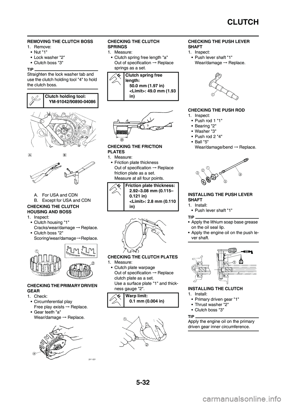
REMOVING THE CLUTCH BOSS
1. Remove:
•Nut "1"
• Lock washer "2"
• Clutch boss "3"
Straighten the lock washer tab and
use the clutch holding tool "4" to hold
the clutch boss.
A. For USA and CDN
B. Except for USA and CDN
CHECKING THE CLUTCH
HOUSING AND BOSS
1. Inspect:
• Clutch housing "1"
Cracks/wear/damage→Replace.
• Clutch boss "2"
Scoring/wear/damage→Replace.
CHECKING THE PRIMARY DRIVEN
GEAR
1. Check:
• Circumferential play
Free play exists→Replace.
• Gear teeth "a"
Wear/damage→Replace.CHECKING THE CLUTCH
SPRINGS
1. Measure:
• Clutch spring free length "a"
Out of specification→Replace
springs as a set.
CHECKING THE FRICTION
PLATES
1. Measure:
• Friction plate thickness
Out of specification→Replace
friction plate as a set.
Measure at all four points.
CHECKING THE CLUTCH PLATES
1. Measure:
• Clutch plate warpage
Out of specification→Replace
clutch plate as a set.
Use a surface plate "1" and thick-
ness gauge "2".CHECKING THE PUSH LEVER
SHAFT
1. Inspect:
• Push lever shaft "1"
Wear/damage→Replace.
CHECKING THE PUSH ROD
1. Inspect:
• Push rod 1 "1"
• Bearing "2"
• Washer "3"
• Push rod 2 "4"
•Ball "5"
Wear/damage/bend→Replace.
INSTALLING THE PUSH LEVER
SHAFT
1. Install:
• Push lever shaft "1"
• Apply the lithium soap base grease
on the oil seal lip.
• Apply the engine oil on the push le-
ver shaft.
INSTALLING THE CLUTCH
1. Install:
• Primary driven gear "1"
• Thrust washer "2"
• Clutch boss "3"
Apply the engine oil on the primary
driven gear inner circumference.
Clutch holding tool:
YM-91042/90890-04086
Clutch spring free
length:
50.0 mm (1.97 in)
in)
Friction plate thickness:
2.92–3.08 mm (0.115–
0.121 in)
in)
Warp limit:
0.1 mm (0.004 in)
Page 136 of 230
5-33
CLUTCH
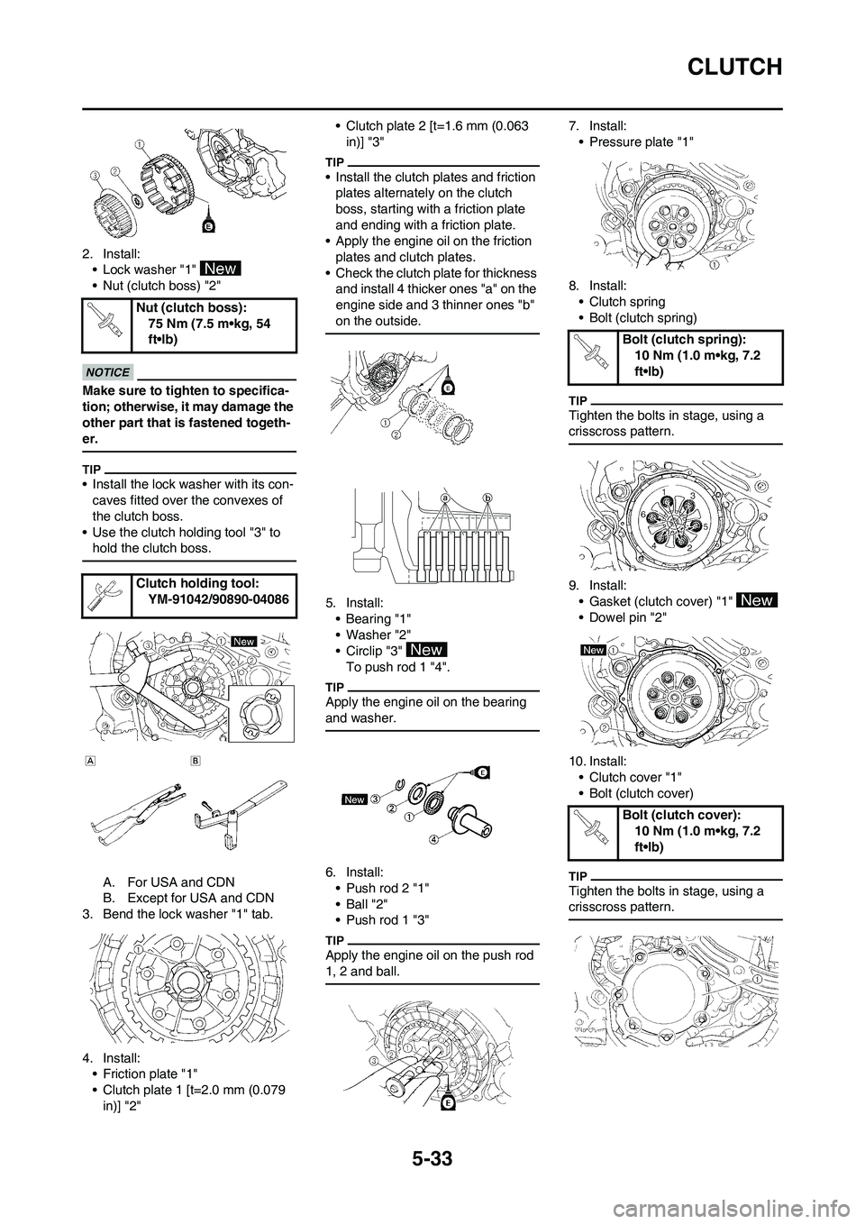
2. Install:
• Lock washer "1"
• Nut (clutch boss) "2"
Make sure to tighten to specifica-
tion; otherwise, it may damage the
other part that is fastened togeth-
er.
• Install the lock washer with its con-
caves fitted over the convexes of
the clutch boss.
• Use the clutch holding tool "3" to
hold the clutch boss.
A. For USA and CDN
B. Except for USA and CDN
3. Bend the lock washer "1" tab.
4. Install:
• Friction plate "1"
• Clutch plate 1 [t=2.0 mm (0.079
in)] "2"• Clutch plate 2 [t=1.6 mm (0.063
in)] "3"
• Install the clutch plates and friction
plates alternately on the clutch
boss, starting with a friction plate
and ending with a friction plate.
• Apply the engine oil on the friction
plates and clutch plates.
• Check the clutch plate for thickness
and install 4 thicker ones "a" on the
engine side and 3 thinner ones "b"
on the outside.
5. Install:
•Bearing "1"
• Washer "2"
• Circlip "3"
To push rod 1 "4".
Apply the engine oil on the bearing
and washer.
6. Install:
• Push rod 2 "1"
• Ball "2"
• Push rod 1 "3"
Apply the engine oil on the push rod
1, 2 and ball.
7. Install:
• Pressure plate "1"
8. Install:
• Clutch spring
• Bolt (clutch spring)
Tighten the bolts in stage, using a
crisscross pattern.
9. Install:
• Gasket (clutch cover) "1"
• Dowel pin "2"
10. Install:
• Clutch cover "1"
• Bolt (clutch cover)
Tighten the bolts in stage, using a
crisscross pattern.
Nut (clutch boss):
75 Nm (7.5 m•kg, 54
ft•lb)
Clutch holding tool:
YM-91042/90890-04086
Bolt (clutch spring):
10 Nm (1.0 m•kg, 7.2
ft•lb)
Bolt (clutch cover):
10 Nm (1.0 m•kg, 7.2
ft•lb)
Page 139 of 230
5-36
OIL FILTER ELEMENT AND WATER PUMP
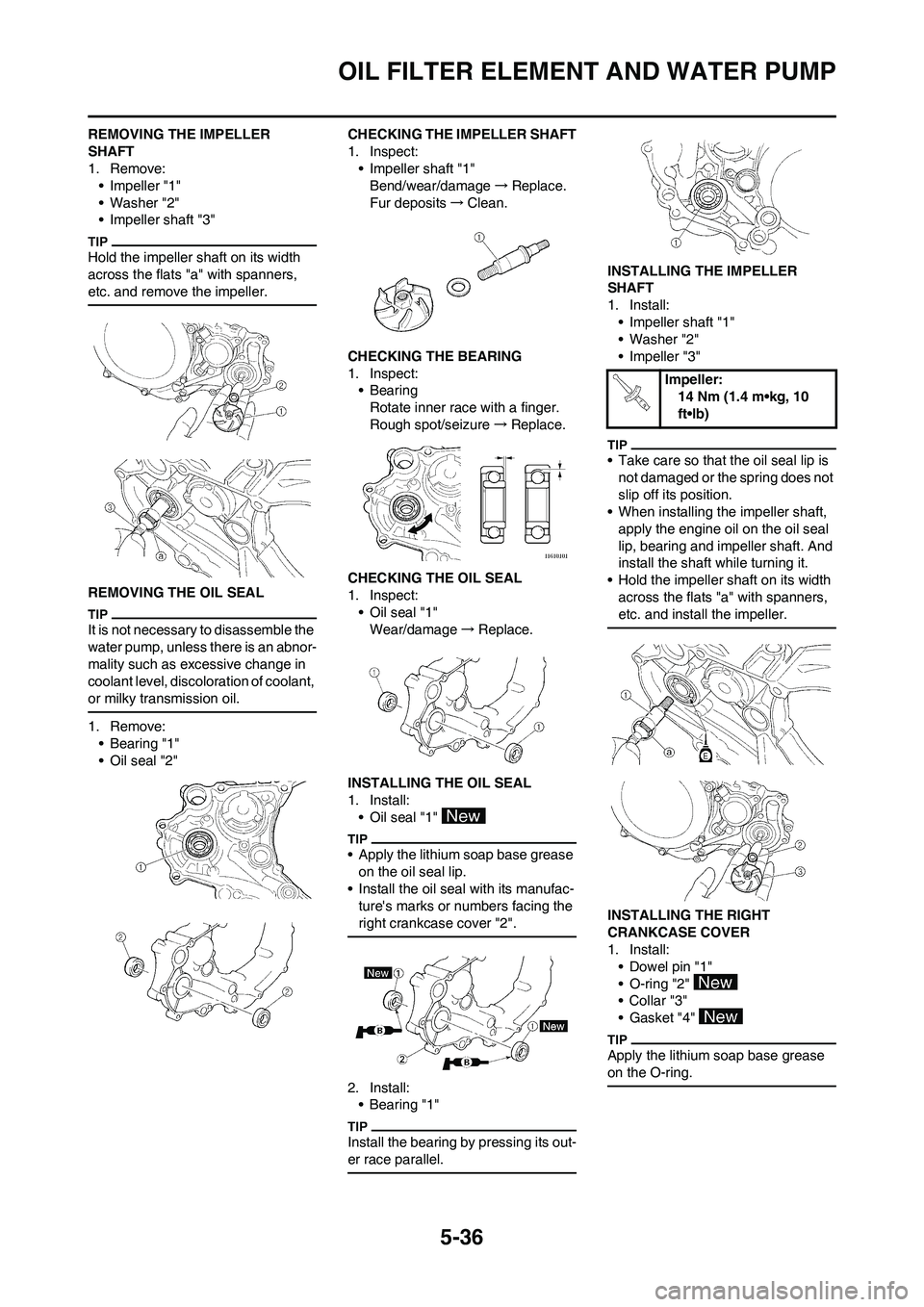
REMOVING THE IMPELLER
SHAFT
1. Remove:
• Impeller "1"
• Washer "2"
• Impeller shaft "3"
Hold the impeller shaft on its width
across the flats "a" with spanners,
etc. and remove the impeller.
REMOVING THE OIL SEAL
It is not necessary to disassemble the
water pump, unless there is an abnor-
mality such as excessive change in
coolant level, discoloration of coolant,
or milky transmission oil.
1. Remove:
• Bearing "1"
• Oil seal "2"CHECKING THE IMPELLER SHAFT
1. Inspect:
• Impeller shaft "1"
Bend/wear/damage→Replace.
Fur deposits→Clean.
CHECKING THE BEARING
1. Inspect:
•Bearing
Rotate inner race with a finger.
Rough spot/seizure→Replace.
CHECKING THE OIL SEAL
1. Inspect:
• Oil seal "1"
Wear/damage→Replace.
INSTALLING THE OIL SEAL
1. Install:
• Oil seal "1"
• Apply the lithium soap base grease
on the oil seal lip.
• Install the oil seal with its manufac-
ture's marks or numbers facing the
right crankcase cover "2".
2. Install:
•Bearing "1"
Install the bearing by pressing its out-
er race parallel.
INSTALLING THE IMPELLER
SHAFT
1. Install:
• Impeller shaft "1"
• Washer "2"
• Impeller "3"
• Take care so that the oil seal lip is
not damaged or the spring does not
slip off its position.
• When installing the impeller shaft,
apply the engine oil on the oil seal
lip, bearing and impeller shaft. And
install the shaft while turning it.
• Hold the impeller shaft on its width
across the flats "a" with spanners,
etc. and install the impeller.
INSTALLING THE RIGHT
CRANKCASE COVER
1. Install:
• Dowel pin "1"
• O-ring "2"
•Collar "3"
• Gasket "4"
Apply the lithium soap base grease
on the O-ring.
Impeller:
14 Nm (1.4 m•kg, 10
ft•lb)
Page 142 of 230
5-39
BALANCER
REMOVING THE BALANCER
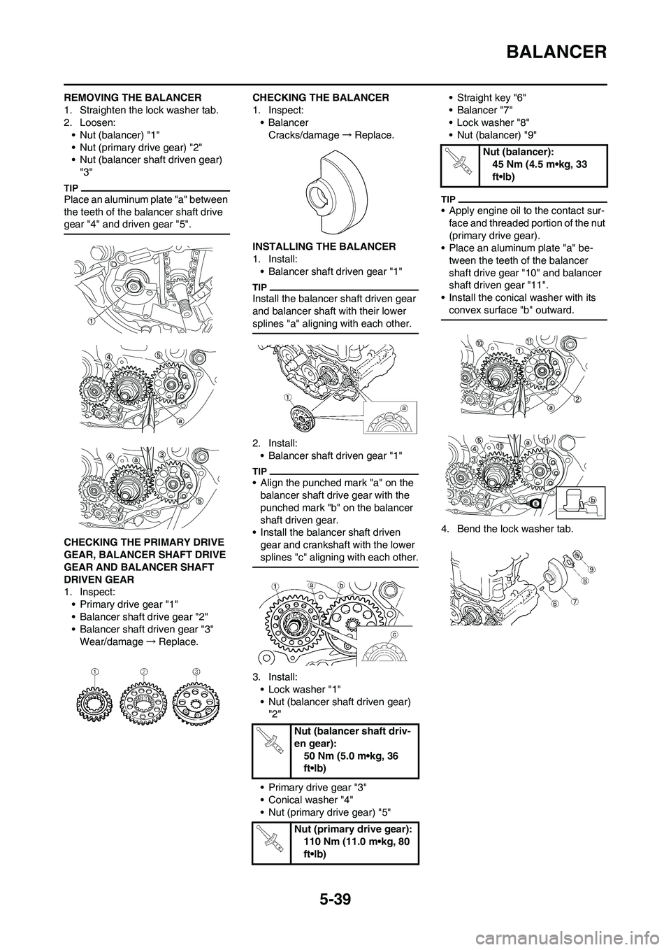
1. Straighten the lock washer tab.
2. Loosen:
• Nut (balancer) "1"
• Nut (primary drive gear) "2"
• Nut (balancer shaft driven gear)
"3"
Place an aluminum plate "a" between
the teeth of the balancer shaft drive
gear "4" and driven gear "5".
CHECKING THE PRIMARY DRIVE
GEAR, BALANCER SHAFT DRIVE
GEAR AND BALANCER SHAFT
DRIVEN GEAR
1. Inspect:
• Primary drive gear "1"
• Balancer shaft drive gear "2"
• Balancer shaft driven gear "3"
Wear/damage→Replace.CHECKING THE BALANCER
1. Inspect:
• Balancer
Cracks/damage→Replace.
INSTALLING THE BALANCER
1. Install:
• Balancer shaft driven gear "1"
Install the balancer shaft driven gear
and balancer shaft with their lower
splines "a" aligning with each other.
2. Install:
• Balancer shaft driven gear "1"
• Align the punched mark "a" on the
balancer shaft drive gear with the
punched mark "b" on the balancer
shaft driven gear.
• Install the balancer shaft driven
gear and crankshaft with the lower
splines "c" aligning with each other.
3. Install:
• Lock washer "1"
• Nut (balancer shaft driven gear)
"2"
• Primary drive gear "3"
• Conical washer "4"
• Nut (primary drive gear) "5"• Straight key "6"
• Balancer "7"
• Lock washer "8"
• Nut (balancer) "9"
• Apply engine oil to the contact sur-
face and threaded portion of the nut
(primary drive gear).
• Place an aluminum plate "a" be-
tween the teeth of the balancer
shaft drive gear "10" and balancer
shaft driven gear "11".
• Install the conical washer with its
convex surface "b" outward.
4. Bend the lock washer tab.
Nut (balancer shaft driv-
en gear):
50 Nm (5.0 m•kg, 36
ft•lb)
Nut (primary drive gear):
110 Nm (11.0 m•kg, 80
ft•lb)
Nut (balancer):
45 Nm (4.5 m•kg, 33
ft•lb)
Page 145 of 230
5-42
OIL PUMP
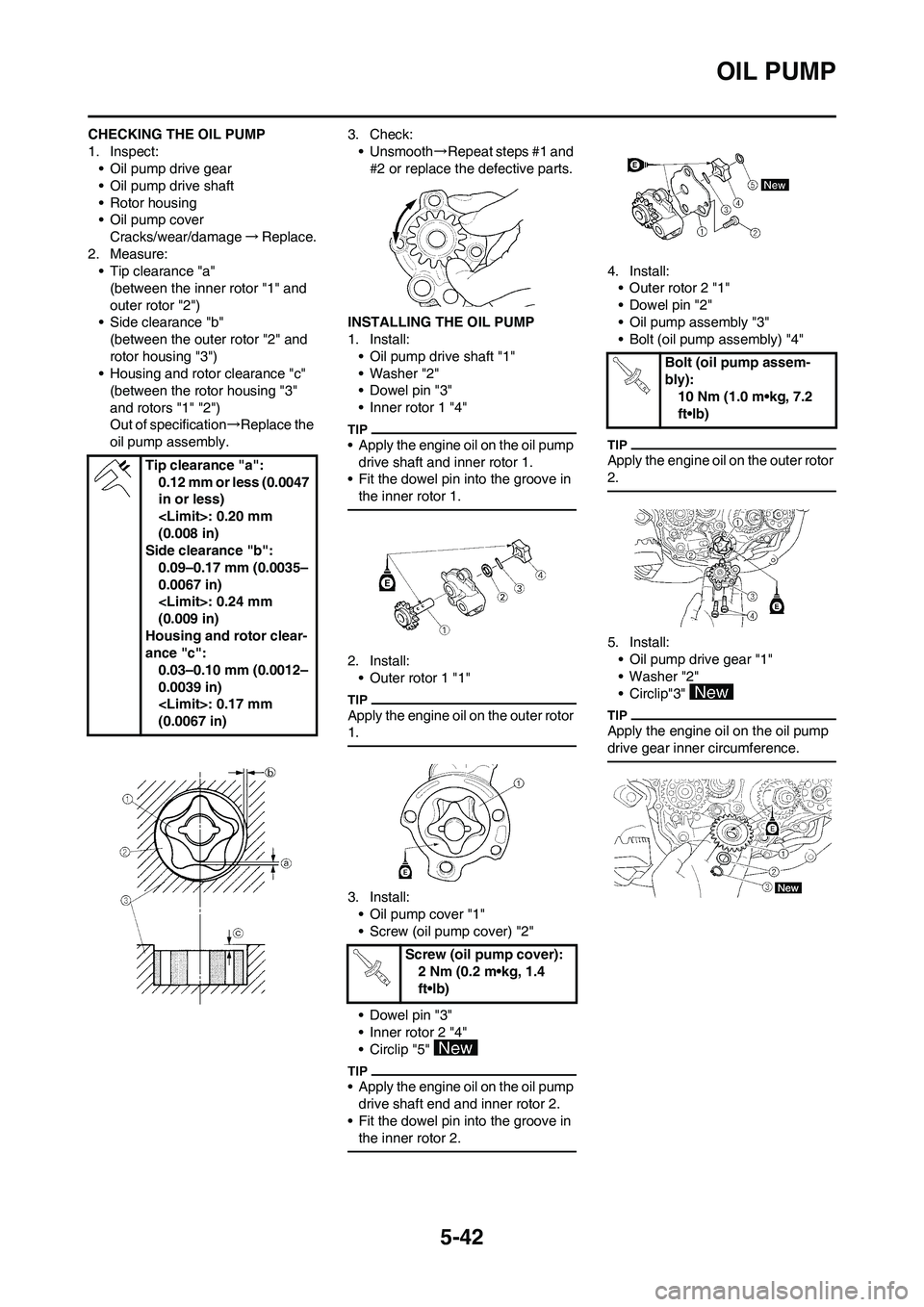
CHECKING THE OIL PUMP
1. Inspect:
• Oil pump drive gear
• Oil pump drive shaft
• Rotor housing
• Oil pump cover
Cracks/wear/damage→Replace.
2. Measure:
• Tip clearance "a"
(between the inner rotor "1" and
outer rotor "2")
• Side clearance "b"
(between the outer rotor "2" and
rotor housing "3")
• Housing and rotor clearance "c"
(between the rotor housing "3"
and rotors "1" "2")
Out of specification→Replace the
oil pump assembly.3. Check:
• Unsmooth→Repeat steps #1 and
#2 or replace the defective parts.
INSTALLING THE OIL PUMP
1. Install:
• Oil pump drive shaft "1"
• Washer "2"
• Dowel pin "3"
• Inner rotor 1 "4"
• Apply the engine oil on the oil pump
drive shaft and inner rotor 1.
• Fit the dowel pin into the groove in
the inner rotor 1.
2. Install:
• Outer rotor 1 "1"
Apply the engine oil on the outer rotor
1.
3. Install:
• Oil pump cover "1"
• Screw (oil pump cover) "2"
• Dowel pin "3"
• Inner rotor 2 "4"
• Circlip "5"
• Apply the engine oil on the oil pump
drive shaft end and inner rotor 2.
• Fit the dowel pin into the groove in
the inner rotor 2.
4. Install:
• Outer rotor 2 "1"
• Dowel pin "2"
• Oil pump assembly "3"
• Bolt (oil pump assembly) "4"
Apply the engine oil on the outer rotor
2.
5. Install:
• Oil pump drive gear "1"
• Washer "2"
• Circlip"3"
Apply the engine oil on the oil pump
drive gear inner circumference.
Tip clearance "a":
0.12 mm or less (0.0047
in or less)
(0.008 in)
Side clearance "b":
0.09–0.17 mm (0.0035–
0.0067 in)
(0.009 in)
Housing and rotor clear-
ance "c":
0.03–0.10 mm (0.0012–
0.0039 in)
(0.0067 in)
Screw (oil pump cover):
2 Nm (0.2 m•kg, 1.4
ft•lb)
Bolt (oil pump assem-
bly):
10 Nm (1.0 m•kg, 7.2
ft•lb)
Page 163 of 230

5-60
CRANKCASE AND CRANKSHAFT
DISASSEMBLING THE
CRANKCASE
1. Separate:
• Right crankcase
• Left crankcase
Separation steps:
a. Remove the crankcase bolts,
hose guide and clutch cable hold-
er.
Loosen each bolt 1/4 of a turn at a
time and after all the bolts are loos-
ened, remove them.
b. Remove the right crankcase.
• Place the crankcase with its left
side downward and split it by insert-
ing a screwdriver tip into the split-
ting slit "a" in the crankcase.
• Lift the right crankcase horizontally
while lightly patting the case split-
ting slit and engine mounting boss
using a soft hammer, and leave the
crankshaft and transmission with
the left crankcase.
Use soft hammer to tap on the
case half. Tap only on reinforced
portions of case. Do not tap on
gasket mating surface. Work slow-
ly and carefully. Make sure the
case halves separate evenly. If the
cases do not separate, check for a
remaining case bolt or fitting. Do
not force.
c. Remove the dowel pins and O-
ring.
REMOVING THE BALANCER
SHAFT
1. Remove:
• Balancer shaft "1"
Remove the balancer shaft with its
flat side "a" facing the crankshaft.
REMOVING THE CRANKSHAFT
1. Remove:
• Crankshaft "1"
Use the crankcase separating
tool "2".
Install the crankcase separating tool
as shown.
Do not use a hammer to drive out
the crankshaft.
REMOVING THE CRANKCASE
BEARING
1. Remove:
•Bearing "1"
• Remove the bearing from the
crankcase by pressing its inner
race.
• Do not use the removed bearing.
CHECKING THE TIMING CHAIN
AND TIMING CHAIN GUIDE
1. Inspect:
• Timing chain
Cracks/stiff→Replace the timing
chain and camshaft sprocket as a
set.
2. Inspect:
• Timing chain guide
Wear/damage→Replace.
CHECKING THE CRANKCASE
1. Inspect:
• Contacting surface "a"
Scratches→Replace.
• Engine mounting boss "b", crank-
case
Cracks/damage→Replace.
2. Inspect:
• Bearing
Rotate inner race with a finger.
Rough spot/seizure→Replace.
3. Inspect:
• Oil seal
Damage→Replace.
Crankcase separating
tool:
YU-A9642/90890-04152
Page 165 of 230

5-62
CRANKCASE AND CRANKSHAFT
4. Apply:
• Sealant
On the right crankcase.
Clean the contacting surface of left
and right crankcase before applying
the sealant.
5. Install:
• Dowel pin "1"
• O-ring "2"
• Right crankcase
To left crankcase.
• Apply the lithium soap base grease
on the O-ring.
• Fit the right crankcase onto the left
crankcase. Tap lightly on the case
with soft hammer.
• When installing the crankcase, the
connecting rod should be posi-
tioned at TDC (top dead center).
6. Tighten:
• Hose guide "1"
• Clutch cable holder "2"
• Bolt (clutch cable holder)
• Bolt (crankcase)
Tighten the crankcase tightening
bolts in stage, using a crisscross pat-
tern.
7. Install:
• Timing chain
• Timing chain guide (intake side)
• Bolt (timing chain guide)
8. Remove:
• Sealant
Forced out on the cylinder mating
surface.
9. Apply:
• Engine oil
To the crank pin, bearing and oil
delivery hole.
10. Check:
• Crankshaft and transmission op-
eration.
Unsmooth operation→Repair. YAMAHA Bond No. 1215
(ThreeBond
® No.1215):
90890-85505
Bolt (clutch cable hold-
er):
10 Nm (1.0 m•kg, 7.2
ft•lb)
Bolt (crankcase):
12 Nm (1.2 m•kg, 8.7
ft•lb)
Bolt (timing chain guide):
10 Nm (1.0 m•kg, 7.2
ft•lb)
Page 168 of 230

5-65
TRANSMISSION, SHIFT CAM AND SHIFT FORK
3. Install:
• Washer "1"
• Circlip "2"
• Be sure the circlip sharp-edged cor-
ner "a" is positioned opposite side
to the washer and gear "b".
• Install the circlip with its ends "c"
settled evenly on the spline crests.
4. Install:
•Collar "1"
• Apply the lithium soap base grease
on the oil seal lip.
• When installing the collar into the
crankcase, pay careful attention to
the crankcase oil seal lip.
5. Install:
• Shift fork 1 (L) "1"
• Shift fork 2 (C) "2"
• Shift fork 3 (R) "3"
• Shift cam "4"
To main axle and drive axle.
• Apply the molybdenum disulfide oil
on the shift fork grooves.
• Apply engine oil to the shift cam
groove, bearing contact surface
and shift fork shaft.
• Mesh the shift fork #1 (L) with the
4th wheel gear "5" and #3 (R) with
the 5th wheel gear "7" on the drive
axle.
• Mesh the shift fork #2 (C) with the
3rd pinion gear "6" on the main ax-
le.
6. Install:
• Transmission assembly "1"
To left crankcase "2".
Apply the engine oil on the bearings
and guide bars.
7. Check:
• Shifter operation
• Transmission operation
Unsmooth operation→Repair.
Page 193 of 230
6-25
HANDLEBAR
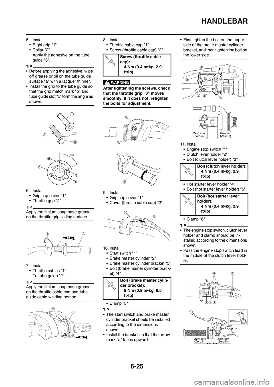
5. Install:
• Right grip "1"
•Collar "2"
Apply the adhesive on the tube
guide "3".
• Before applying the adhesive, wipe
off grease or oil on the tube guide
surface "a" with a lacquer thinner.
• Install the grip to the tube guide so
that the grip match mark "b" and
tube guide slot "c" form the angle as
shown.
6. Install:
• Grip cap cover "1"
• Throttle grip "2"
Apply the lithium soap base grease
on the throttle grip sliding surface.
7. Install:
• Throttle cables "1"
To tube guide "2".
Apply the lithium soap base grease
on the throttle cable end and tube
guide cable winding portion.
8. Install:
• Throttle cable cap "1"
• Screw (throttle cable cap) "2"
After tightening the screws, check
that the throttle grip "3" moves
smoothly. If it does not, retighten
the bolts for adjustment.
9. Install:
• Grip cap cover "1"
• Cover (throttle cable cap) "2"
10. Install:
• Start switch "1"
• Brake master cylinder "2"
• Brake master cylinder bracket "3"
• Bolt (brake master cylinder brack-
et) "4"
•Clamp "5"
• The start switch and brake master
cylinder bracket should be installed
according to the dimensions
shown.
• Install the bracket so that the arrow
mark "a" faces upward.• First tighten the bolt on the upper
side of the brake master cylinder
bracket, and then tighten the bolt on
the lower side.
11. Install:
• Engine stop switch "1"
• Clutch lever holder "2"
• Bolt (clutch lever holder) "3"
• Hot starter lever holder "4"
• Bolt (hot starter lever holder) "5"
• Clamp "6"
• The engine stop switch, clutch lever
holder and clamp should be in-
stalled according to the dimensions
shown.
• Pass the engine stop switch lead in
the middle of the clutch lever hold-
er.
Screw (throttle cable
cap):
4 Nm (0.4 m•kg, 2.9
ft•lb)
Bolt (brake master cylin-
der bracket):
9 Nm (0.9 m•kg, 6.5
ft•lb)
Bolt (clutch lever holder):
4 Nm (0.4 m•kg, 2.9
ft•lb)
Bolt (hot starter lever
holder):
4 Nm (0.4 m•kg, 2.9
ft•lb)
Page 204 of 230

6-36
REAR SHOCK ABSORBER
REAR SHOCK ABSORBER
REMOVING THE REAR SHOCK ABSORBER
Order Part name Q'ty Remarks
Hold the machine by placing the suitable stand
under the engine.Refer to "HANDLING NOTE".
Seat and side cover Refer to "REMOVING THE SEAT, FUEL
TANK AND SIDE COVERS" section in the
CHAPTER 3.
Silencer Refer to "REMOVING THE EXHAUST PIPE
AND SILENCER" section in the CHAPTER 3.
Drain the coolant.Refer to "CHANGING THE COOLANT" sec-
tion in the CHAPTER 3.
Catch tank breather hose Disconnect at the catch tank side.
Catch tank hose Disconnect at the catch tank side.
Air induction hose (air cut-off valve-air filter case) Disconnect at the air filter case side.
Cylinder head breather hose Disconnect at the air filter case side.
BatteryRefer to "CHECKING AND CHARGING THE
BATTERY" section in the CHAPTER 3.
Disconnect the starter relay coupler.
Starter motor lead Disconnect at the starter relay side.
1 Locking tie 4