ABS YAMAHA WR 450F 2010 Owners Manual
[x] Cancel search | Manufacturer: YAMAHA, Model Year: 2010, Model line: WR 450F, Model: YAMAHA WR 450F 2010Pages: 230, PDF Size: 13.87 MB
Page 10 of 230
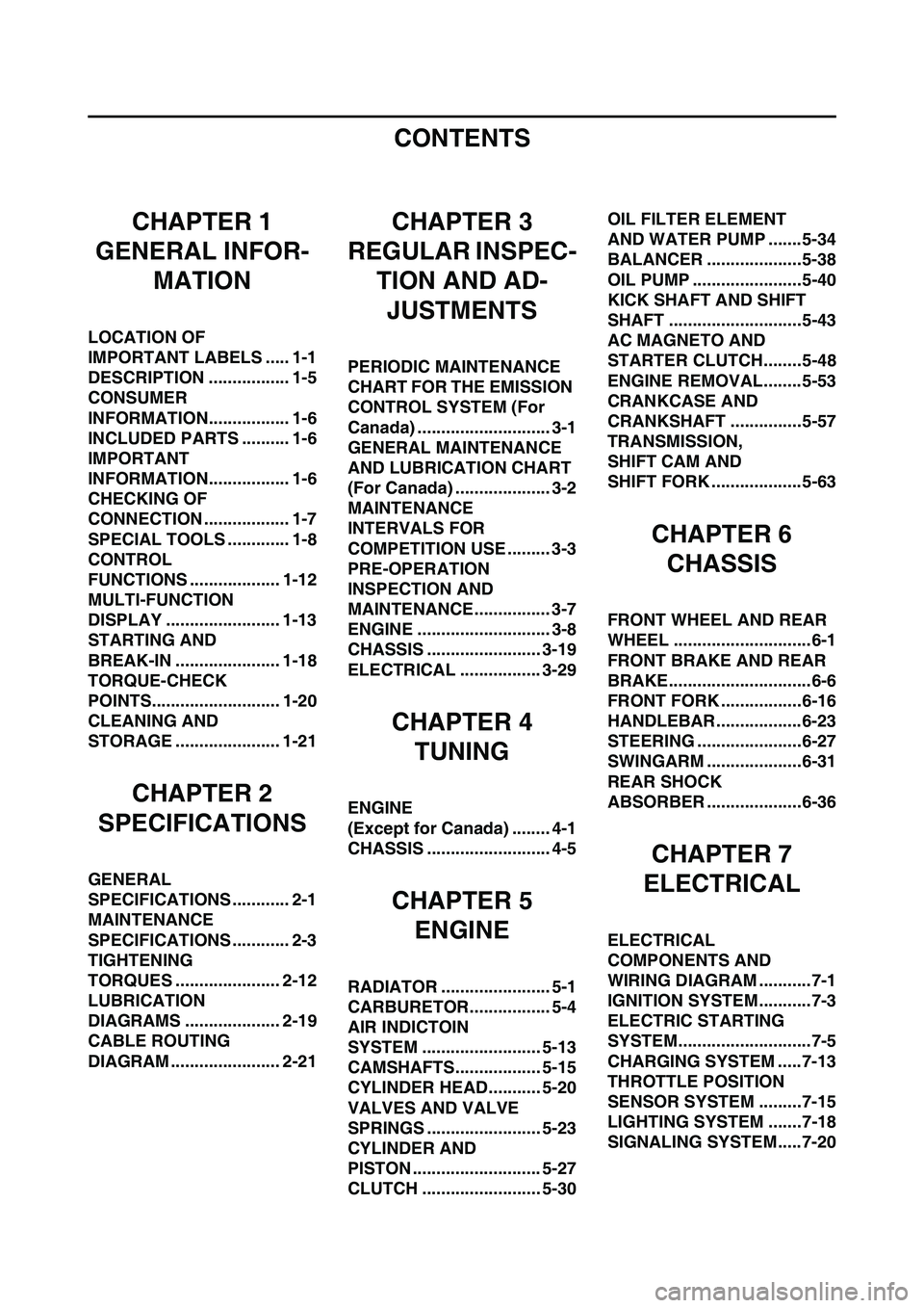
CONTENTS
CHAPTER 1
GENERAL INFOR-
MATION
LOCATION OF
IMPORTANT LABELS ..... 1-1
DESCRIPTION ................. 1-5
CONSUMER
INFORMATION................. 1-6
INCLUDED PARTS .......... 1-6
IMPORTANT
INFORMATION................. 1-6
CHECKING OF
CONNECTION .................. 1-7
SPECIAL TOOLS ............. 1-8
CONTROL
FUNCTIONS ................... 1-12
MULTI-FUNCTION
DISPLAY ........................ 1-13
STARTING AND
BREAK-IN ...................... 1-18
TORQUE-CHECK
POINTS........................... 1-20
CLEANING AND
STORAGE ...................... 1-21
CHAPTER 2
SPECIFICATIONS
GENERAL
SPECIFICATIONS ............ 2-1
MAINTENANCE
SPECIFICATIONS ............ 2-3
TIGHTENING
TORQUES ...................... 2-12
LUBRICATION
DIAGRAMS .................... 2-19
CABLE ROUTING
DIAGRAM ....................... 2-21
CHAPTER 3
REGULAR INSPEC-
TION AND AD-JUSTMENTS
PERIODIC MAINTENANCE
CHART FOR THE EMISSION
CONTROL SYSTEM (For
Canada) ............................ 3-1
GENERAL MAINTENANCE
AND LUBRICATION CHART
(For Canada) .................... 3-2
MAINTENANCE
INTERVALS FOR
COMPETITION USE ......... 3-3
PRE-OPERATION
INSPECTION AND
MAINTENANCE................ 3-7
ENGINE ............................ 3-8
CHASSIS ........................ 3-19
ELECTRICAL ................. 3-29
CHAPTER 4 TUNING
ENGINE
(Except for Canada) ........ 4-1
CHASSIS .......................... 4-5
CHAPTER 5
ENGINE
RADIATOR ....................... 5-1
CARBURETOR................. 5-4
AIR INDICTOIN
SYSTEM ......................... 5-13
CAMSHAFTS.................. 5-15
CYLINDER HEAD........... 5-20
VALVES AND VALVE
SPRINGS ........................ 5-23
CYLINDER AND
PISTON ........................... 5-27
CLUTCH ......................... 5-30 OIL FILTER ELEMENT
AND WATER PUMP .......5-34
BALANCER ....................5-38
OIL PUMP .......................5-40
KICK SHAFT AND SHIFT
SHAFT ............................5-43
AC MAGNETO AND
STARTER CLUTCH........5-48
ENGINE REMOVAL........5-53
CRANKCASE AND
CRANKSHAFT ...............5-57
TRANSMISSION,
SHIFT CAM AND
SHIFT FORK ...................5-63
CHAPTER 6
CHASSIS
FRONT WHEEL AND REAR
WHEEL .............................6-1
FRONT BRAKE AND REAR
BRAKE..............................6-6
FRONT FORK .................6-16
HANDLEBAR..................6-23
STEERING ......................6-27
SWINGARM ....................6-31
REAR SHOCK
ABSORBER ....................6-36
CHAPTER 7
ELECTRICAL
ELECTRICAL
COMPONENTS AND
WIRING DIAGRAM ...........7-1
IGNITION SYSTEM...........7-3
ELECTRIC STARTING
SYSTEM............................7-5
CHARGING SYSTEM .....7-13
THROTTLE POSITION
SENSOR SYSTEM .........7-15
LIGHTING SYSTEM .......7-18
SIGNALING SYSTEM.....7-20
Page 23 of 230
1-13
MULTI-FUNCTION DISPLAY
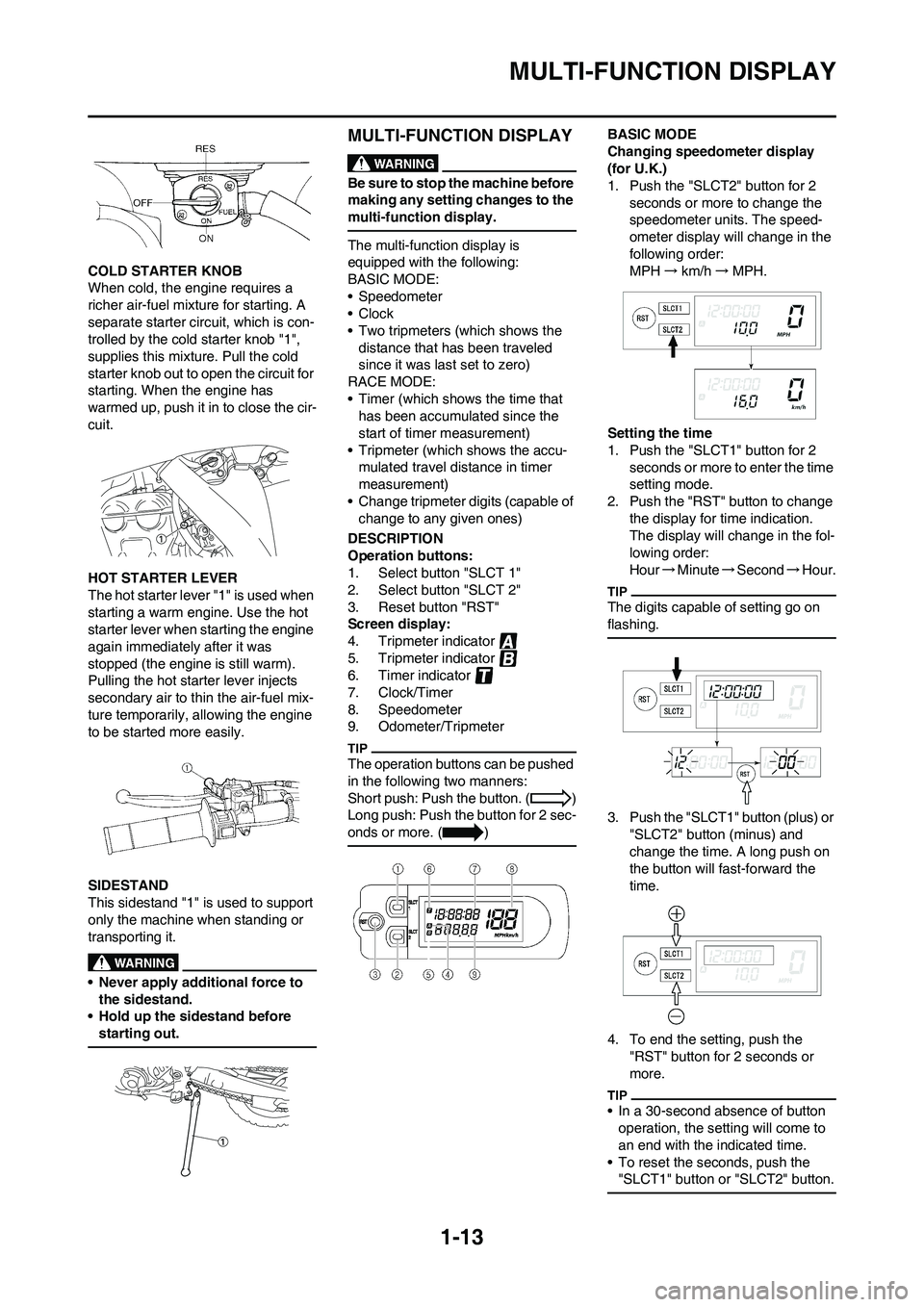
COLD STARTER KNOB
When cold, the engine requires a
richer air-fuel mixture for starting. A
separate starter circuit, which is con-
trolled by the cold starter knob "1",
supplies this mixture. Pull the cold
starter knob out to open the circuit for
starting. When the engine has
warmed up, push it in to close the cir-
cuit.
HOT STARTER LEVER
The hot starter lever "1" is used when
starting a warm engine. Use the hot
starter lever when starting the engine
again immediately after it was
stopped (the engine is still warm).
Pulling the hot starter lever injects
secondary air to thin the air-fuel mix-
ture temporarily, allowing the engine
to be started more easily.
SIDESTAND
This sidestand "1" is used to support
only the machine when standing or
transporting it.
• Never apply additional force to the sidestand.
• Hold up the sidestand before
starting out.
MULTI-FUNCTION DISPLAY
Be sure to stop the machine before
making any setting changes to the
multi-function display.
The multi-function display is
equipped with the following:
BASIC MODE:
• Speedometer
•Clock
• Two tripmeters (which shows the distance that has been traveled
since it was last set to zero)
RACE MODE:
• Timer (which shows the time that has been accumulated since the
start of timer measurement)
• Tripmeter (which shows the accu- mulated travel distance in timer
measurement)
• Change tripmeter digits (capable of change to any given ones)
DESCRIPTION
Operation buttons:
1. Select button "SLCT 1"
2. Select button "SLCT 2"
3. Reset button "RST"
Screen display:
4. Tripmeter indicator
5. Tripmeter indicator
6. Timer indicator
7. Clock/Timer
8. Speedometer
9. Odometer/Tripmeter
The operation buttons can be pushed
in the following two manners:
Short push: Push the button. ( )
Long push: Push the button for 2 sec-
onds or more. ( )
BASIC MODE
Changing speedometer display
(for U.K.)
1. Push the "SLCT2" button for 2 seconds or more to change the
speedometer units. The speed-
ometer display will change in the
following order:
MPH →km/h →MPH.
Setting the time
1. Push the "SLCT1" button for 2 seconds or more to enter the time
setting mode.
2. Push the "RST" button to change the display for time indication.
The display will change in the fol-
lowing order:
Hour →Minute →Second →Hour.
The digits capable of setting go on
flashing.
3. Push the "SLCT1" button (plus) or
"SLCT2" button (minus) and
change the time. A long push on
the button will fast-forward the
time.
4. To end the setting, push the "RST" button for 2 seconds or
more.
• In a 30-second absence of button operation, the setting will come to
an end with the indicated time.
• To reset the seconds, push the "SLCT1" button or "SLCT2" button.
Page 30 of 230
1-20
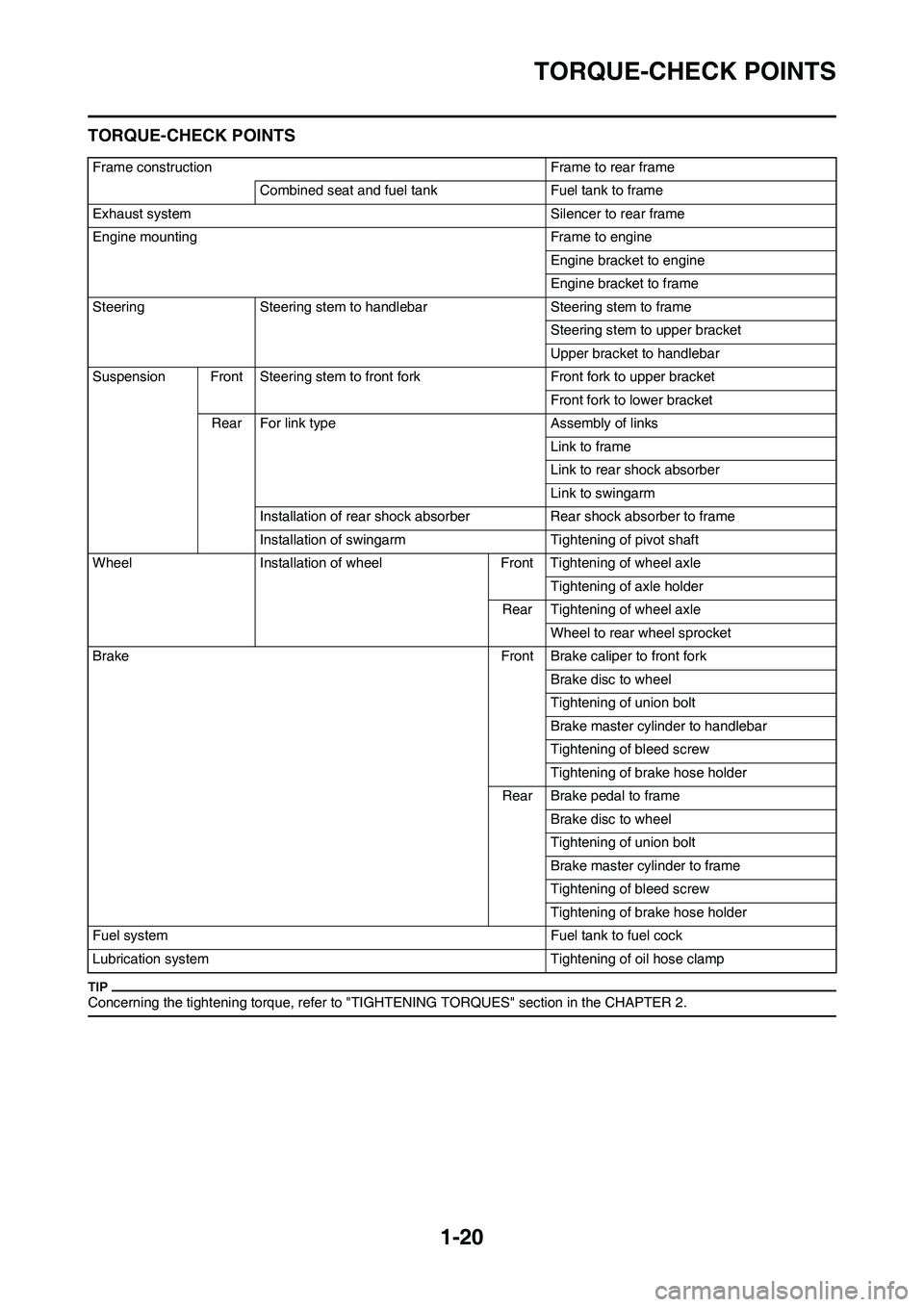
TORQUE-CHECK POINTS
TORQUE-CHECK POINTS
Concerning the tightening torque, refer to "TIGHTENING TORQUES" section in the CHAPTER 2.
Frame construction Frame to rear frameCombined seat and fuel tank Fuel tank to frame
Exhaust system Silencer to rear frame
Engine mounting Frame to engine Engine bracket to engine
Engine bracket to frame
Steering Steering stem to handlebar Steering stem to frame Steering stem to upper bracket
Upper bracket to handlebar
Suspension Front Steering stem to front fork Front fork to upper bracket
Front fork to lower bracket
Rear For link type Assembly of links Link to frame
Link to rear shock absorber
Link to swingarm
Installation of rear shock absorber Rear shock absorber to frame
Installation of swingarm Tightening of pivot shaft
Wheel Installation of wheel Front Tightening of wheel axle Tightening of axle holder
Rear Tightening of wheel axle Wheel to rear wheel sprocket
Brake Front Brake caliper to front fork Brake disc to wheel
Tightening of union bolt
Brake master cylinder to handlebar
Tightening of bleed screw
Tightening of brake hose holder
Rear Brake pedal to frame Brake disc to wheel
Tightening of union bolt
Brake master cylinder to frame
Tightening of bleed screw
Tightening of brake hose holder
Fuel system Fuel tank to fuel cock
Lubrication system Tighteni ng of oil hose clamp
Page 34 of 230
2-3
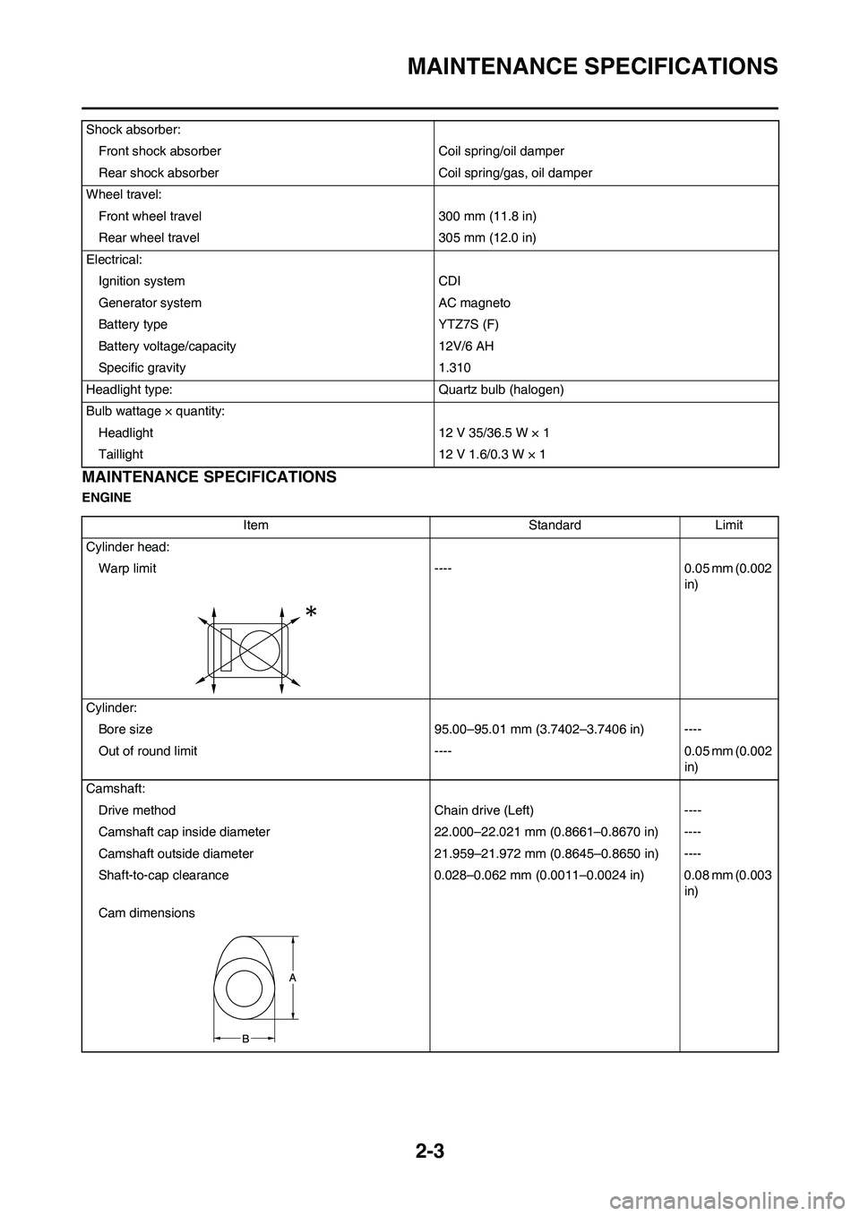
MAINTENANCE SPECIFICATIONS
MAINTENANCE SPECIFICATIONS
ENGINEShock absorber:
Front shock absorber Coil spring/oil damper
Rear shock absorber Coil spring/gas, oil damper
Wheel travel:
Front wheel travel 300 mm (11.8 in)
Rear wheel travel 305 mm (12.0 in)
Electrical:
Ignition system CDI
Generator system AC magneto
Battery type YTZ7S (F)
Battery voltage/capacity 12V/6 AH
Specific gravity 1.310
Headlight type: Quartz bulb (halogen)
Bulb wattage × quantity:
Headlight 12 V 35/36.5 W × 1
Taillight 12 V 1.6/0.3 W × 1
Item Standard Limit
Cylinder head:
Warp limit ---- 0.05 mm (0.002
in)
Cylinder:
Bore size 95.00–95.01 mm (3.7402–3.7406 in) ----
Out of round limit ---- 0.05 mm (0.002
in)
Camshaft:
Drive method Chain drive (Left) ----
Camshaft cap inside diameter 22.000–22.021 mm (0.8661–0.8670 in) ----
Camshaft outside diameter 21.959–21.972 mm (0.8645–0.8650 in) ----
Shaft-to-cap clearance 0.028–0.062 mm (0.0011–0.0024 in) 0.08 mm (0.003
in)
Cam dimensions
Page 40 of 230
2-9
MAINTENANCE SPECIFICATIONS
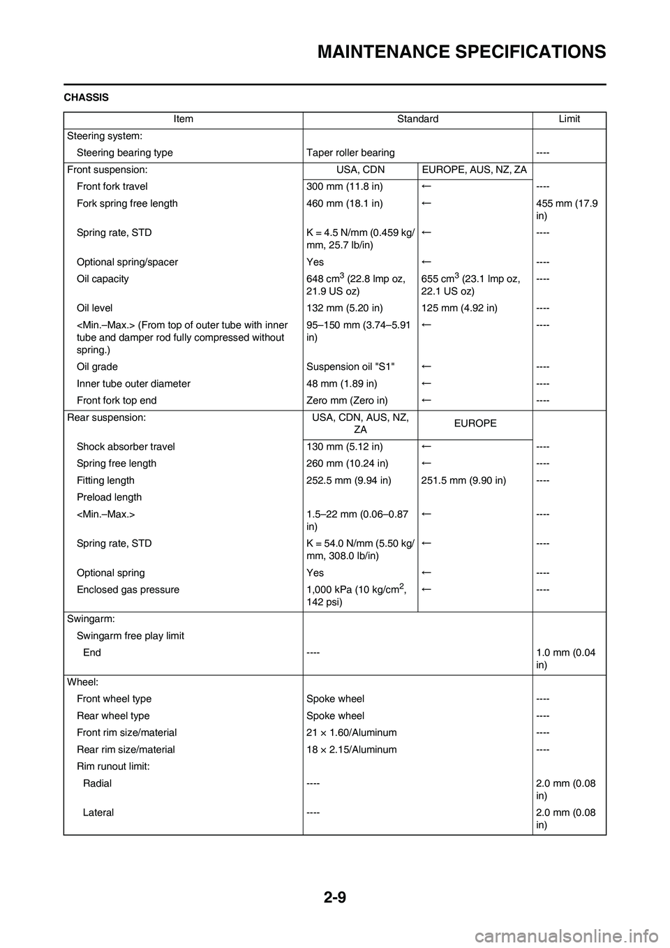
CHASSIS
Item Standard Limit
Steering system:
Steering bearing typeTaper roller bearing ----
Front suspension: USA, CDN EUROPE, AUS, NZ, ZA
Front fork travel 300 mm (11.8 in)←----
Fork spring free length 460 mm (18.1 in)←455 mm (17.9
in)
Spring rate, STD K = 4.5 N/mm (0.459 kg/
mm, 25.7 lb/in)←----
Optional spring/spacer Yes←----
Oil capacity 648 cm
3 (22.8 lmp oz,
21.9 US oz)655 cm3 (23.1 lmp oz,
22.1 US oz)----
Oil level 132 mm (5.20 in) 125 mm (4.92 in) ----
tube and damper rod fully compressed without
spring.)95–150 mm (3.74–5.91
in)←----
Oil grade Suspension oil "S1"←----
Inner tube outer diameter 48 mm (1.89 in)←----
Front fork top end Zero mm (Zero in)←----
Rear suspension: USA, CDN, AUS, NZ,
ZAEUROPE
Shock absorber travel 130 mm (5.12 in)←----
Spring free length 260 mm (10.24 in)←----
Fitting length 252.5 mm (9.94 in) 251.5 mm (9.90 in) ----
Preload length
in)←----
Spring rate, STD K = 54.0 N/mm (5.50 kg/
mm, 308.0 lb/in)←----
Optional spring Yes←----
Enclosed gas pressure 1,000 kPa (10 kg/cm
2,
142 psi)←----
Swingarm:
Swingarm free play limit
End ---- 1.0 mm (0.04
in)
Wheel:
Front wheel type Spoke wheel ----
Rear wheel typeSpoke wheel ----
Front rim size/material 21 × 1.60/Aluminum ----
Rear rim size/material 18 × 2.15/Aluminum ----
Rim runout limit:
Radial ---- 2.0 mm (0.08
in)
Lateral ---- 2.0 mm (0.08
in)
Page 46 of 230

2-15
TIGHTENING TORQUES
△Driven sprocket and wheel hub M8 × 1.25 6 50 5.0 36
△Nipple (spoke) — 72 3 0.3 2.2
△Disc cover and rear brake caliper M6 × 1.0 2 10 1.0 7.2
△Protector and rear brake caliper M6 × 1.0 2 7 0.7 5.1
Chain puller adjust bolt and locknut M8 × 1.25 2 19 1.9 13
Engine mounting:
△Engine upper bracket and frame M10 × 1.25 4 55 5.5 40
△Engine lower bracket and frame M8 × 1.25 4 34 3.4 24
△Engine and engine bracket (lower) M10 × 1.25 1 53 5.3 38
△Engine and engine bracket (upper) M10 × 1.25 1 55 5.5 40
△Engine and frame (lower) M10 × 1.25 1 53 5.3 38
△Engine guard M6 × 1.0 3 7 0.7 5.1
Regulator mounting M6 × 1.0 2 7 0.7 5.1
△Pivot shaft and nut M16 × 1.5 1 85 8.5 61
△Relay arm and swingarm M14 × 1.5 1 70 7.0 50
△Relay arm and connecting rod M14 × 1.5 1 80 8.0 58
△Connecting rod and frame M14 × 1.5 1 80 8.0 58
△Rear shock absorber and frame M10 × 1.25 1 56 5.6 40
△Rear shock absorber and relay arm M10 × 1.25 1 53 5.3 38
△Rear frame and frame (upper) M8 × 1.25 1 38 3.8 27
△Rear frame and frame (lower) M8 × 1.25 2 32 3.2 23
△Swingarm and brake hose holder M5 × 0.8 4 2 0.2 1.4
Swingarm and patch M4 × 0.7 4 2 0.2 1.4
Drive chain tensioner mounting (upper) M8 × 1.25 1 16 1.6 11
Drive chain tensioner mounting (lower) M8 × 1.25 1 16 1.6 11
Chain support and swingarm M6 × 1.0 3 7 0.7 5.1
Seal guard and swingarm M5 × 0.8 4 6 0.6 4.3
△Fuel tank mounting M6 × 1.0 2 9 0.9 6.5
△Fuel tank and fuel cock M6 × 1.0 2 4 0.4 2.9
Fuel tank and seat set bracket M6 × 1.0 1 7 0.7 5.1
Fuel tank and fuel tank bracket M6 × 1.0 4 7 0.7 5.1
Seat mounting M8 × 1.25 2 22 2.2 16
△Side cover mounting M6 × 1.0 2 7 0.7 5.1
△Air scoop and fuel tank M6 × 1.0 6 7 0.7 5.1
△Air scoop and radiator panel (lower) M6 × 1.0 2 6 0.6 4.3
△Front fender mounting M6 × 1.0 4 7 0.7 5.1
△Rear fender mounting (front) M6 × 1.0 2 7 0.7 5.1
△Rear fender mounting (rear) M6 × 1.0 2 11 1.1 8.0
Multi-function display bracket mounting M6 × 1.0 2 7 0.7 5.1
Multi-function display mounting M5 × 0.8 2 4 0.4 2.9
Plate 1 and protector M5 × 0.8 2 4 0.4 2.9
Plate 2 and protector — 2 0.5 0.05 0.36
Speed sensor lead holder and under bracket M6 × 1.0 1 13 1.3 9.4
Headlight body and headlight unit — 2 1 0.1 0.7Part to be tightened Thread size Q'tyTightening torque
Nm m•kg ft•lb
Page 53 of 230

2-22
CABLE ROUTING DIAGRAM
A. Insert the end of the fuel tank
breather hose into the hole in
the steering stem.
B. Fasten the throttle cable, hot
starter cable and rectifier/regula-
tor lead onto the frame. Locate
the clamp under the throttle ca-
ble on the right side of the frame,
and face its ends, as well as the
tie ends, downward.
C. Fasten the diode (at the mark-
ing), throttle cable and hot start-
er cable onto the frame. Locate
the clamp end facing toward the
lower right of the frame and with
the tie end facing downward.
D. Fasten the wire harness, throttle
position sensor lead and clutch
cable onto the frame. Pass the
clamp through the hole in the
stay (air cut-off valve). Locate
the clamp end facing toward the
lower side of the frame and cut
off the tie end.
E. Pass the carburetor breather
hoses, carburetor overflow hose
and catch tank breather hose
between the connecting rod and
cross tube (frame).
F. Pass the neutral switch lead on
the inside of the engine bracket.
G. Fasten the neutral switch lead
and AC magneto lead onto the
frame. Locate the clamp end
facing toward the outside of the
frame and tie end facing toward
the rear of the frame.
H. Fasten the AC magneto lead
and neutral switch lead onto the
frame. Locate the clamp end
facing toward the rear of the
frame and cut off the tie end.
I. Pass the neutral switch lead and
AC magneto lead on the inside
of the wire harness.
J. Fasten the AC magneto lead
and neutral switch lead onto the
frame.
K. Pass the wire harness through
the cable guide.
L. Locate the couplers in the frame
recess.
M. Pass the carburetor breather
hoses, carburetor overflow hose
and catch tank breather hose so
that the hoses do not contact the
rear shock absorber.
N. Secure the coupler by pushing it
into the hole in the headlight
unit.
O. Fasten the throttle position sen-
sor lead and the hot starter ca-
ble.P. Locate the clamp between the
hot starter cable protector and
rubber cap.
Page 55 of 230
2-24
CABLE ROUTING DIAGRAM
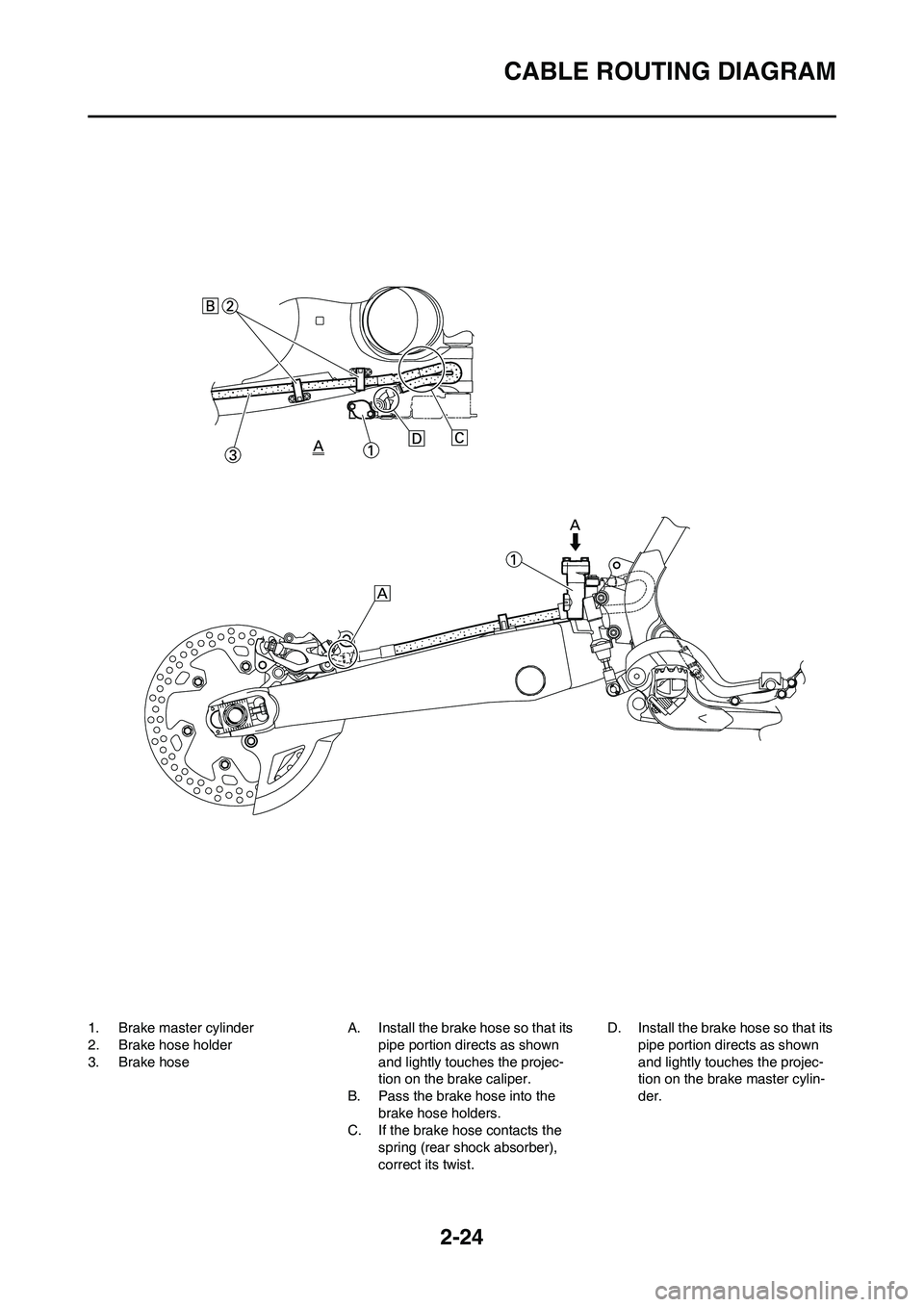
1. Brake master cylinder
2. Brake hose holder
3. Brake hoseA. Install the brake hose so that its
pipe portion directs as shown
and lightly touches the projec-
tion on the brake caliper.
B. Pass the brake hose into the
brake hose holders.
C. If the brake hose contacts the
spring (rear shock absorber),
correct its twist.D. Install the brake hose so that its
pipe portion directs as shown
and lightly touches the projec-
tion on the brake master cylin-
der.
Page 62 of 230
3-3
MAINTENANCE INTERVALS FOR COMPETITION USE
• The air filter needs more frequent service if you are riding in unusually wet or dusty areas.
• Hydraulic brake service
• After disassembling the brake master cylinders and calipers, always change the fluid. Regularly check the brake fluid
levels and fill the reservoirs as required.
• Every two years replace the internal components of the brake master cylinders and calipers, and change the brake fluid.
• Replace the brake hoses every four years and if cracked or damaged.
MAINTENANCE INTERVALS FOR COMPETITION USE
• The following schedule is intended as a general guide to maintenance and lubrication. Bear in mind that such factors as
weather, terrain, geographical location, and individual usage will alter the required maintenance and lubrication intervals.
If you are a doubt as to what intervals to follow in maintaining and lubricating your machine, consult your Yamaha dealer.
• Periodic inspection is essential in making full use of the machine performance. The service life of the parts varies sub-
stantially according to the environment in which the machine runs (e.g., rain, dirt, etc.). Therefore, earlier inspection is
required by reference to the list below.
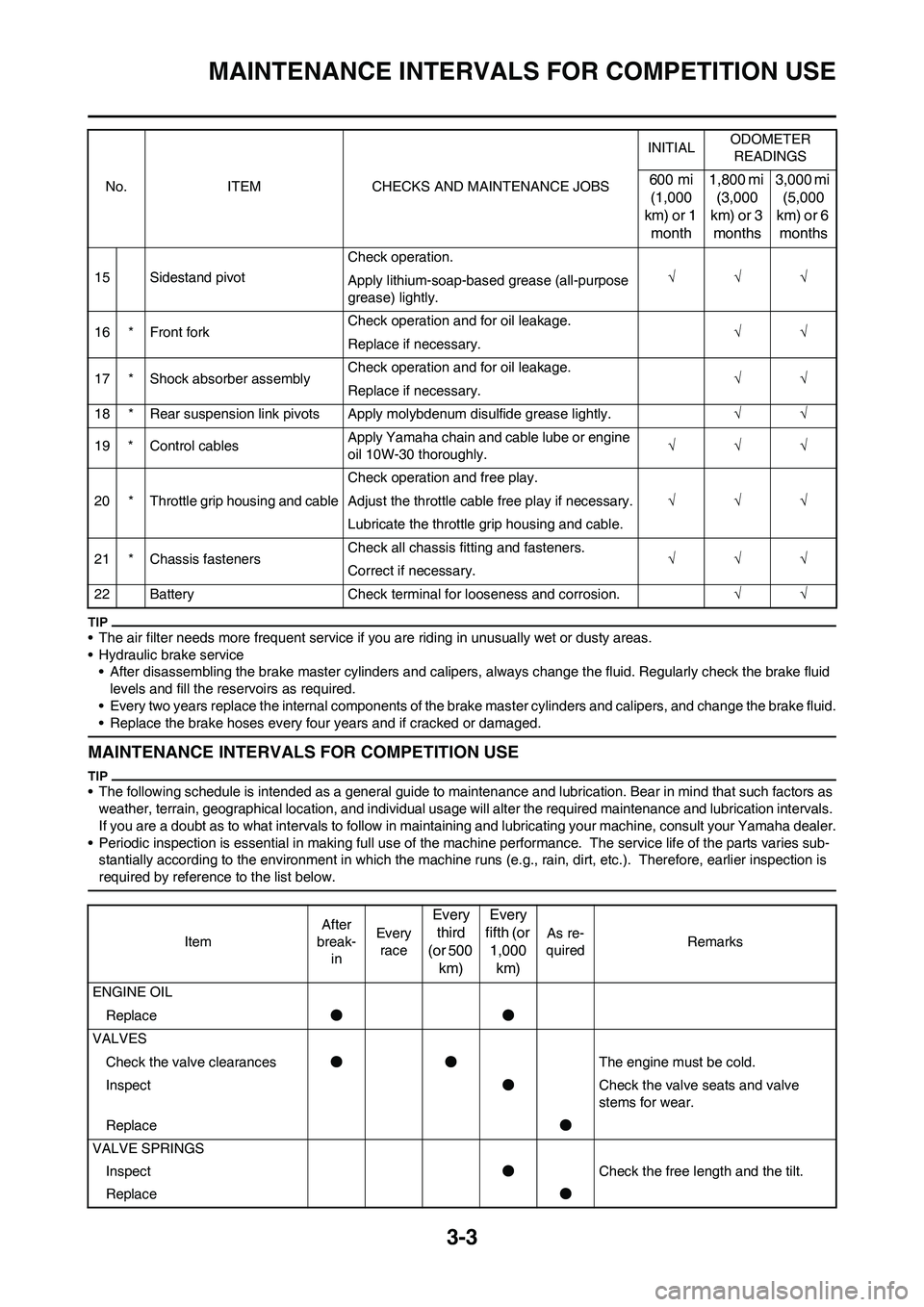
15 Sidestand pivotCheck operation.
√√√
Apply lithium-soap-based grease (all-purpose
grease) lightly.
16 * Front forkCheck operation and for oil leakage.
√√
Replace if necessary.
17 * Shock absorber assemblyCheck operation and for oil leakage.
√√
Replace if necessary.
18 * Rear suspension link pivots Apply molybdenum disulfide grease lightly.√√
19 * Control cablesApply Yamaha chain and cable lube or engine
oil 10W-30 thoroughly.√√√
20 * Throttle grip housing and cableCheck operation and free play.
√√√ Adjust the throttle cable free play if necessary.
Lubricate the throttle grip housing and cable.
21 * Chassis fastenersCheck all chassis fitting and fasteners.
√√√
Correct if necessary.
22 Battery Check terminal for looseness and corrosion.√√ No. ITEM CHECKS AND MAINTENANCE JOBSINITIALODOMETER
READINGS
600 mi
(1,000
km) or 1
month1,800 mi
(3,000
km) or 3
months3,000 mi
(5,000
km) or 6
months
ItemAfter
break-
inEvery
race
Every
third
(or 500
km)Every
fifth (or
1,000
km)
As re-
quiredRemarks
ENGINE OIL
Replace●●
VALVES
Check the valve clearances●●The engine must be cold.
Inspect●Check the valve seats and valve
stems for wear.
Replace●
VALVE SPRINGS
Inspect●Check the free length and the tilt.
Replace●
Page 65 of 230
3-6
MAINTENANCE INTERVALS FOR COMPETITION USE
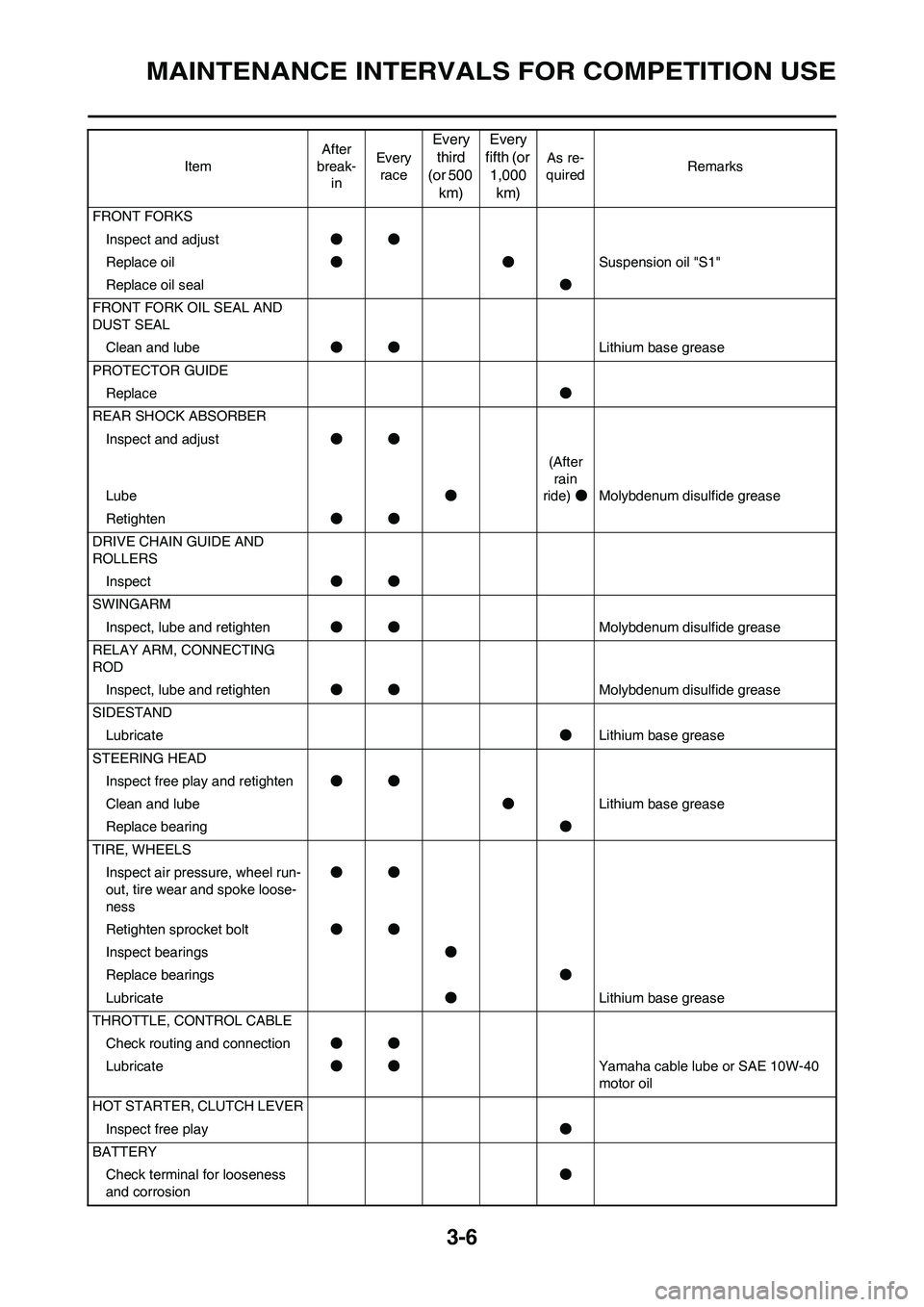
FRONT FORKS
Inspect and adjust●●
Replace oil●●Suspension oil "S1"
Replace oil seal●
FRONT FORK OIL SEAL AND
DUST SEAL
Clean and lube●●Lithium base grease
PROTECTOR GUIDE
Replace●
REAR SHOCK ABSORBER
Inspect and adjust●●
Lube●(After
rain
ride)●Molybdenum disulfide grease
Retighten●●
DRIVE CHAIN GUIDE AND
ROLLERS
Inspect●●
SWINGARM
Inspect, lube and retighten●●Molybdenum disulfide grease
RELAY ARM, CONNECTING
ROD
Inspect, lube and retighten●●Molybdenum disulfide grease
SIDESTAND
Lubricate●Lithium base grease
STEERING HEAD
Inspect free play and retighten●●
Clean and lube●Lithium base grease
Replace bearing●
TIRE, WHEELS
Inspect air pressure, wheel run-
out, tire wear and spoke loose-
ness●●
Retighten sprocket bolt●●
Inspect bearings●
Replace bearings●
Lubricate●Lithium base grease
THROTTLE, CONTROL CABLE
Check routing and connection●●
Lubricate●●Yamaha cable lube or SAE 10W-40
motor oil
HOT STARTER, CLUTCH LEVER
Inspect free play●
BATTERY
Check terminal for looseness
and corrosion● ItemAfter
break-
inEvery
race
Every
third
(or 500
km)Every
fifth (or
1,000
km)
As re-
quiredRemarks