diagram YAMAHA WR 450F 2016 Owner's Manual
[x] Cancel search | Manufacturer: YAMAHA, Model Year: 2016, Model line: WR 450F, Model: YAMAHA WR 450F 2016Pages: 426, PDF Size: 10.86 MB
Page 92 of 426

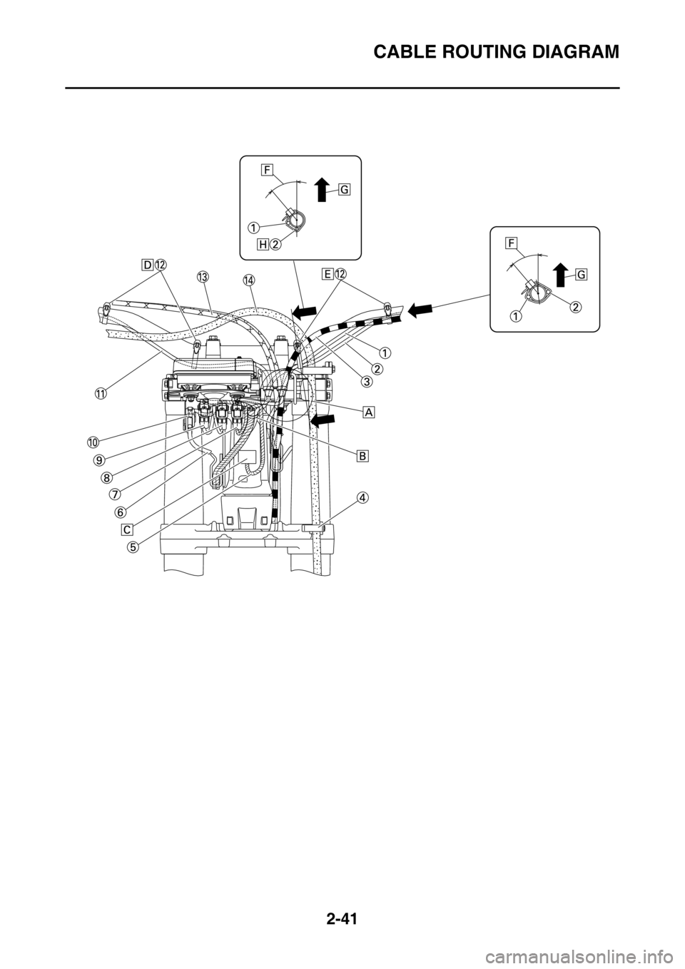
CABLE ROUTING DIAGRAM
2-41
Page 93 of 426

CABLE ROUTING DIAGRAM
2-42
1. Clutch switch lead
2. Engine stop switch lead
3. Clutch cable
4. Brake hose guide
5. Headlight lead
6. Speed sensor lead
7. Indicator light coupler
8. Meter assembly optional switch coupler
9. Meter assembly coupler
10. Speed sensor coupler
11. Start switch lead
12. Plastic band
13. Throttle cable
14. Front brake hose
A. Route the throttle cable, clutch cable, clutch switch lead, engine stop switch lead and start
switch lead between the cable guide of the meter
bracket and handle crown. The cables and leads
may be routed in any order.
B. Clamp the wire harness, clutch switch lead and start switch lead to the meter bracket. The clamp
shall be located at a pos ition where there is no
slack with the handle turned fully to the left.
C. Connect the headlight lead to the headlight.
D. Clamp the start switch lead to the handlebar by the plastic band.
E. Clamp the engine stop switch lead and clutch switch lead to the handlebar by the plastic band.
F. 40°±10°
G. Vertical direction
H. Pass the engine stop switch lead under the han- dlebar.
Page 94 of 426

CABLE ROUTING DIAGRAM
2-43
Page 95 of 426

CABLE ROUTING DIAGRAM
2-44
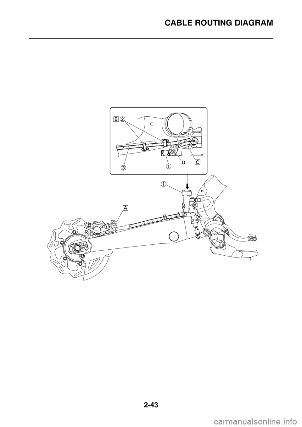
1. Brake master cylinder
2. Brake hose holder
3. Brake hoses
A. While installing the brake hose, direct a bend in its pipe portion as shown, and bring it into contact
with the projection on the brake caliper.
B. Pass the brake hose into the brake hose holders.
C. If the brake hose interfer es with the rear shock
absorber, correct its twist.
D. While installing the brake hose, direct a bend in its pipe portion as shown, and bring it into contact
with the projection on the brake master cylinder.
Page 96 of 426

CABLE ROUTING DIAGRAM
2-45
Page 329 of 426

9
ELECTRICAL SYSTEM
IGNITION SYSTEM.......................................................................................... 9-2
CIRCUIT DIAGRAM ................................................................................... 9-2
TROUBLESHOOTING ............................................................................... 9-4
ELECTRIC STARTING SYSTEM ..................................................................... 9-6
CIRCUIT DIAGRAM ................................................................................... 9-6
STARTING CIRCUIT CUT-OFF SYSTEM OPERATION ........................... 9-8
TROUBLESHOOTING ............................................................................. 9-10
CHARGING SYSTEM ..................................................................................... 9-12
CIRCUIT DIAGRAM ................................................................................. 9-12
TROUBLESHOOTING ............................................................................. 9-14
LIGHTING SYSTEM ....................................................................................... 9-16
CIRCUIT DIAGRAM ................................................................................. 9-16
TROUBLESHOOTING ............................................................................. 9-18
SIGNALING SYSTEM .................................................................................... 9-20
CIRCUIT DIAGRAM ................................................................................. 9-20
TROUBLESHOOTING ............................................................................. 9-22
COOLING SYSTEM ........................................................................................ 9-24
CIRCUIT DIAGRAM ................................................................................. 9-24
TROUBLESHOOTING ............................................................................. 9-26
FUEL INJECTION SYSTEM ........................................................................... 9-28
CIRCUIT DIAGRAM ................................................................................. 9-28
ECU SELF-DIAGNOSTIC FUNCTION ..................................................... 9-30
TROUBLESHOOTING METHOD ............................................................. 9-31
YAMAHA DIAGNOSTIC TOOL ................................................................ 9-32
TROUBLESHOOTING DETAILS ............................................................. 9-35
FUEL PUMP SYSTEM .................................................................................... 9-56
CIRCUIT DIAGRAM ................................................................................. 9-56
TROUBLESHOOTING ............................................................................. 9-58
Page 332 of 426

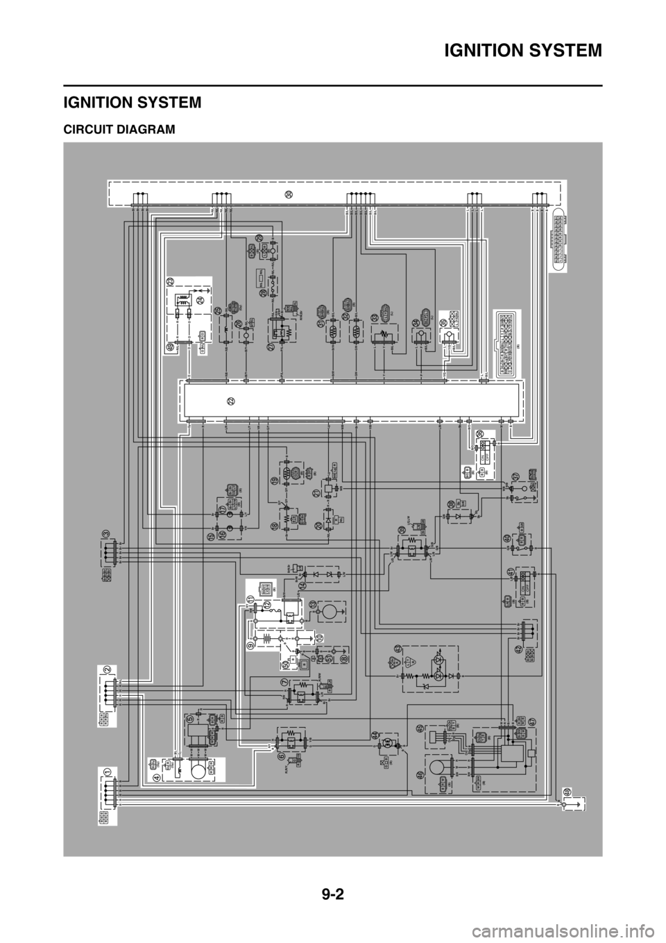
IGNITION SYSTEM
9-2
EAS2GC1358
IGNITION SYSTEM
EAS2GC1359CIRCUIT DIAGRAM
ONOFF
ONOFF
BBB
BBB
RRR
RRR/L
Br Br BrBr Br
(Gy)
(Gy)B/LGyWW W BGy
BR
WW W
BR
R,R/Y
G
R
Y/B
R,R/W
Br
RL/R
(B)R/YR/WBr/WL/G
Br/W,BrL/W
(B)
(B) Br BrL/Y
Y/R
G/YBrBB
BrBrL/YY/W
(B) (B)B BGG/Y
RR/L
RLg
W/B
(B)
BGyBr RW/BB/LLYP
G/WB/Y
R/BLgG/YW
Br/W
OL/RY/BB/OL/BSbY/R
L/Y P/L
Y/G
(Gy)R/L R/BR/LB/Y
R/WR/L
R/W,BrP/L
R/L R/L
(B)
(B) (B)
(L)
(L) (B)
BR/LLBR/L R/L R/L R/L R/L B/L B/L B/L B/L B/L B/L B/LLLLLBBBB
Br Br Br Br
B/LBr/W
B/LG/WLYB/L
B/LPLB/LY/GL
(B)
(B)B/OBBBSbW/B
Sb
SbG/B
L/G,L/WL/BBrG/BG/BB
BB
(B)
(B)L/BBBB
Br Br
Br BrBr
BB
LY
(B)
(B)
(B)
(B)
(B)
GB
ChDg YB
BRW
BrRBW
B/WRW
Ch DgYBBrR/WBW
R
O
OR/L
BB
B
B
BBBBBB
RRRRRR/L
BrBrBrBrBr
Br
Br
BrBrBrBrR/LR/LR/LR/LR/L
B
LLLP
PL
Y
Y
RR
Br
R/LR/L
R/L
P/L
P/L
R/L
R/L
R/LR/B
R/B
L/RL/Y
L/Y
Y/R
Y/R
G/Y
G/YG/Y
G/Y
B/Y
B/Y
R/LB/LB/L
B/LB/LB/LY/G
Y/GB/L
B/OL/BY/BW/B
W/B
G/B
L/B
W/BW/B
L/BL/BL/GL/W
L/W
L/R
Br/W
Br/W
R/W
R/W
R/Y
R/Y
G/BG/B
G/B
B/O
B/LB/LB/LB/LB/LB/LB/L
G/W
G/W
Br/W
Br/W
R/WR/WBr
O
OOR
OR
RGy
LLLLBBBB
B
B
B
B
BB
B
B
RRWW
Y
Y
Dg
Dg
Ch
Ch
RW
BrBrBrBr
Br
B
W
Sb
SbSb
SbBr
Br
B
Br
Lg
Lg
R/L
R
R
RR
Gy
BB
WWWWWW
R
RRGGBB
B
Y/B
RBBB
BB
B
BBB
Br
Br
Br
L/G
B/L
B/WB/W
BB
Page 335 of 426

IGNITION SYSTEM
9-5
8. Check the lean angle sensor.Refer to “CHECKING THE LEAN
ANGLE SENSOR” on page 9-75. NG
Replace the lean angle sensor.
OK
9. Check the entire ignition system’s wiring.
Refer to “CIRCUIT DIAGRAM” on
page 9-2. NG
Properly connect or repair the ignition sys-
tem’s wiring.
OK
Replace the ECU.
Page 336 of 426

ELECTRIC STARTING SYSTEM
9-6
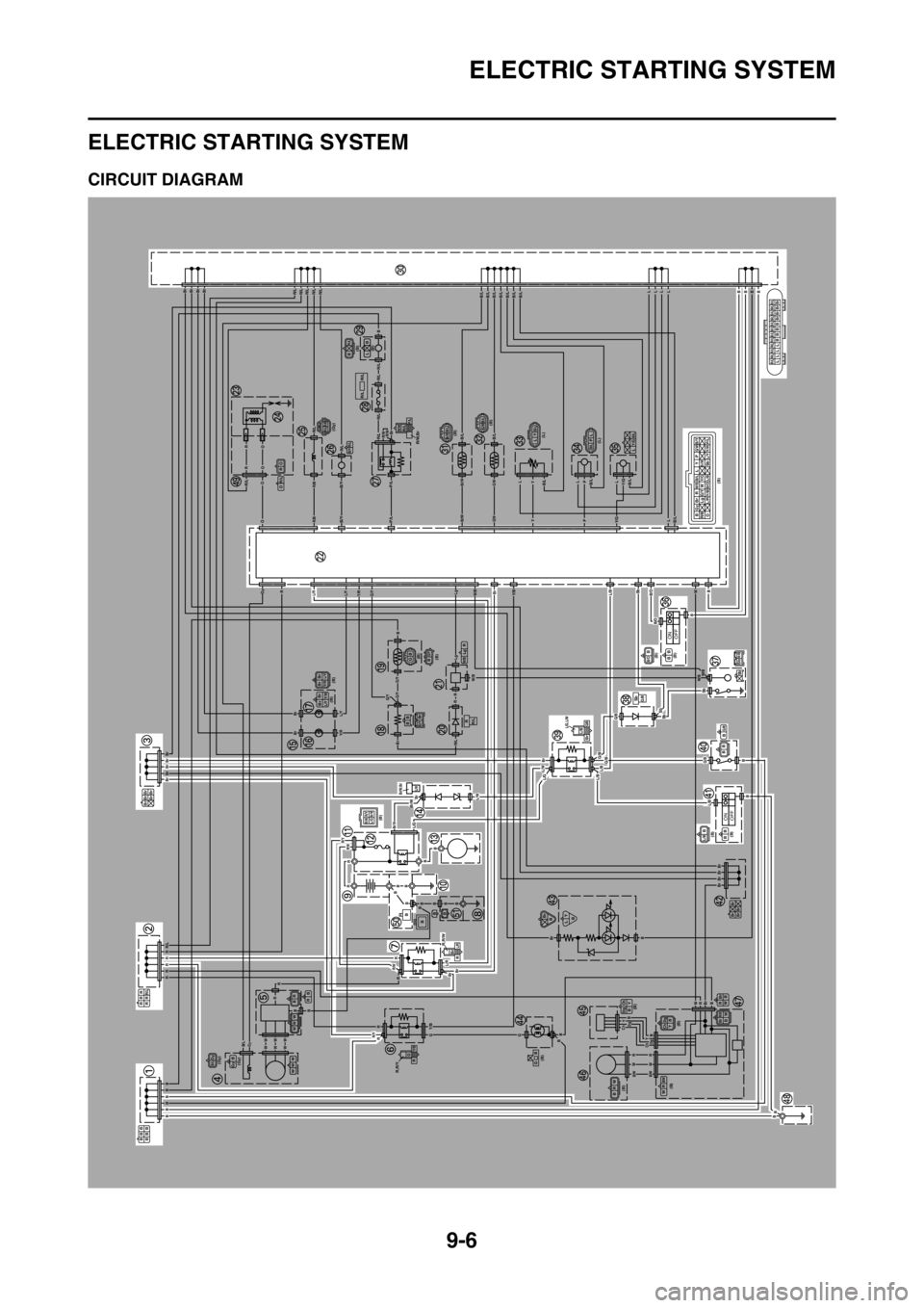
EAS27160
ELECTRIC STARTING SYSTEM
EAS2GC1361CIRCUIT DIAGRAM
ONOFF
ONOFF
BBB
BBB
RRR
RRR/L
Br Br Br
Br Br
(Gy)
(Gy)B/LGyWW W BGy
BR
WW W
BR
R,R/Y
G
R
Y/B
R,R/W
Br
RL/R
(B)R/YR/WBr/WL/G
Br/W,BrL/W
(B)
(B) Br BrL/Y
Y/R
G/YBrBB
BrBrL/YY/W
(B) (B)B BGG/Y
RR/L
RLg
W/B
(B)
BGyBr RW/BB/LLYP
G/WB/Y
R/BLgG/YW
Br/W
OL/RY/BB/OL/BSbY/R
L/Y P/L
Y/G
(Gy)R/L R/BR/LB/Y
R/WR/L
R/W,BrP/L
R/L R/L
(B)
(B) (B)
(L)
(L) (B)
BR/LLBR/L R/L R/L R/L R/L B/L B/L B/L B/L B/L B/L B/LLLLLBBBB
Br Br Br Br
B/LBr/W
B/LG/WLYB/L
B/LPLB/LY/GL
(B)
(B)B/OBBBSbW/B
Sb
SbG/B
L/G,L/WL/BBrG/BG/BB
BB
(B)
(B)L/BBBB
Br Br
Br BrBr
BB
LY
(B)
(B)
(B)
(B)
(B)
GB
ChDg YB
BRW
BrRBW
B/WRW
Ch DgYBBrR/WBW
R
O
OR/L
BB
B
B
BBBBBB
RRRRRR/L
BrBrBrBrBr
Br
Br
BrBrBrBrR/LR/LR/LR/LR/L
B
LLLP
PL
Y
Y
RR
Br
R/LR/L
R/L
P/L
P/L
R/L
R/L
R/LR/B
R/B
L/RL/Y
L/Y
Y/R
Y/R
G/Y
G/YG/Y
G/Y
B/Y
B/Y
R/LB/LB/L
B/LB/LB/LY/G
Y/GB/L
B/OL/BY/BW/B
W/B
G/B
L/B
W/BW/B
L/BL/BL/GL/W
L/W
L/R
Br/W
Br/W
R/W
R/W
R/Y
R/Y
G/BG/B
G/B
B/O
B/LB/LB/LB/LB/LB/LB/L
G/W
G/W
Br/W
Br/W
R/WR/WBr
O
O
RGy
LLLLBBBB
B
B
B
B
BB
B
B
RRWW
Y
Y
Dg
Dg
Ch
Ch
RW
BrBrBrBr
Br
B
W
Sb
SbSb
SbBr
Br
B
Br
Lg
Lg
R/L
R
R
RR
Gy
BB
WWWWWW
R
RRGGBB
B
Y/B
R
BB
Br
Br
Br
L/G
B/L
B/WB/W
OR
OR
BBB
B
BBBBB
Page 341 of 426

ELECTRIC STARTING SYSTEM
9-11
8. Check the main relay.Refer to “CHECKING THE RE-
LAYS” on page 9-72. NG
Replace the main relay.
OK
9. Check the neutral switch. Refer to “CHECKING THE
SWITCHES” on page 9-64. NG
Replace the neutral switch.
OK
10.Check the clutch switch. Refer to “CHECKING THE
SWITCHES” on page 9-64. NG
Replace the clutch switch.
OK
11.Check the engine stop switch. Refer to “CHECKING THE
SWITCHES” on page 9-64. NG
Replace the engine stop switch.
OK
12.Check the start switch. Refer to “CHECKING THE
SWITCHES” on page 9-64. NG
Replace the start switch.
OK
13.Check the entire starting system’s wiring.
Refer to “CIRCUIT DIAGRAM” on
page 9-6. NG
Properly connect or repair the starting sys-
tem’s wiring.
OK
Replace the ECU.