ad blue YAMAHA WR 450F 2016 Owners Manual
[x] Cancel search | Manufacturer: YAMAHA, Model Year: 2016, Model line: WR 450F, Model: YAMAHA WR 450F 2016Pages: 426, PDF Size: 10.86 MB
Page 85 of 426

CABLE ROUTING DIAGRAM
2-34
1. Clutch cable
2. Throttle cable (return)
3. Throttle cable (pull)
4. Engine stop switch lead
5. Coupler for connecting optional part
6. Engine stop switch coupler
7. Rectifier/regulator coupler
8. AC magneto lead
9. Starter knob/idle screw
10. Engine ground sub-lead
11. Starter motor lead
12. Radiator fan fuse
13. Taillight lead
14. Headlight relay (yellow tape)
15. Starting circuit cut-off relay (no identification tape)
16. Diode
17. Holder plate
18. Left of the vehicle:radiator fan motor relay (blue tape)
Right of the vehicle:main relay (red tape)
19. Neutral switch lead
20. Front engine bracket
21. Plastic locking tie
22. Radiator hose
23. Neutral switch coupler
24. Crankshaft position sensor coupler
25. Tension arm
26. Wire harness
27. Tank rail
28. Rectifier/regulator
29. Rectifier/regulator bracket
30. Rear frame
31. Side cover 5
32. Crankcase cover
33. Crankcase
34. Lead holder
35. Frame
36. Engine ground sub-lead coupler
A. Pass the engine stop switch lead between the frame and the cable holder.
B. Insert the coupler for connecting optional part into the connector, and fix it to the bracket.
C. Insert and fix the engine stop switch coupler to the bracket.
D. Insert and fix the rectifie r/regulator coupler to the
bracket.
E. Pass the AC magneto lead to the front of the ve- hicle beyond the starter knob/idle screw and to
the rear of the vehicle beyond the radiator. No
pinch is allowed between the radiator and the
tension arm.
F. Make sure that there is no slack so that the starter motor lead cannot touch the end of the bolt.
G. Place the rear grommet of the starter motor lead matching the rear end of the side cover.
H. Insert the radiator fan motor fuse into the protru- sion of the holder plate.
I. Place the diode on top of the rear fender on the inner side of the rear frame.
J. Bring the neutral switch lead into line with the crankcase cover with no sag allowed.
K. Route the AC magneto lead inside the starter clutch cover.
L. Pass the neutral switch l ead to the inside of the
front engine bracket (the side of the vehicle).
M. Insert the plastic locking tie into the bracket hole and clamp the clutch cable. Clamp it so that the
lock of the plastic locking tie faces downward,
and then cut off the end of the plastic locking tie. N. Pass the clutch cable
with no downward sag al-
lowed.
O. Place the grommet of the clutch cable so that it contacts the radiator hose. Route the clutch cable
outside the neutral switch lead, AC magneto lead
and starter motor lead.
P. Route each lead so that the leads are not pinched
between the radiator hose and the frame.
Q. 40 mm (1.57 in)
R. Clamp the clutch cable, AC magneto lead, neu- tral switch lead and starter motor lead by the plas-
tic locking tie. Make sure that they are clamped at
the positioning tapes in the clutch cable and the
starter motor lead. Make the lock on the plastic
locking tie face the front of the vehicle, and cut
the end.
S. Clamp the starter motor lead to the inside of the tension arm with a plastic locking tie. Clamp it so
that the lock of the plastic locking tie faces up-
ward and outward, and do not cut off the end of
the plastic locking tie. R oute the lead so that there
is no slack at the bottom from the clamp position
onwards.
T. After connecting the neutral switch coupler, at- tach the coupler cover.
U. After connecting the crankshaft position sensor coupler, attach the coupler cover.
V. Pass the rectifier/regulator lead to the inside of the tension arm (the side of the vehicle).
W. Pass the main harness to the front of the radiator
hose (the front of the vehicle), and to the inside of
the clutch cable (the side of the vehicle).
X. Pass the engine stop switch lead between the coupler for connecting optional part and the tank
rail, with the lead on the main harness side facing
the top of the vehicle.
Y. Insert the starter motor lead completely into the end of the side cover 5.
Z. Clamp the clutch cable at the front of the lead (the
front of the vehicle).
AA.Insert the clip of the pl astic locking tie into the
frame. Face the lock of the plastic locking tie for-
ward, and then cut off the end.
Page 91 of 426

CABLE ROUTING DIAGRAM
2-40
1. Battery negative lead
2. Fuel hose
3. Fuel pump coupler
4. Fuel pump lead
5. Resistor
6. Resistor coupler
7. Battery positive lead
8. Lean angle sensor
9. Starter motor lead
10. Radiator fan motor relay (blue tape)
11. Main relay (red tape)
12. Wire harness
13. Ground lead coupler
14. Starter relay coupler
15. Starter relay
16. Cross member
17. Diode
18. Taillight lead
19. Clamp
20. Fuel tank
21. Damper
22. Rear frame
23. Side cover 6
24. Plastic locking tie
A. After connecting the fuel pump coupler, attach the coupler cover.
B. Pass the fuel hose to the front of the battery.
C. Route the resistor lead to the outside of the leads.
D. Connect the battery positive lead to the starter re- lay terminal (in the left side of the vehicle).
E. Insert the protruding end of the wire harness into
the battery bracket hole and holder plate hole.
F. After connecting the negative lead coupler, place it on the right side of the battery.
G. Route the diode under the cross member and place it on top of the rear fender.
H. Secure the two ends of the taillight coupler with the starter motor lead.
I. Route the taillight lead so that it does not slack at
the rear of the vehicle.
J. Clamp the taillight lead and insert the clip into the rear fender. Clamp it so that the lock faces in-
ward, and then cut off the excess end.
K. Lower end of the rear frame
L. Clamp it so that the lock of the plastic locking tie
faces downward, insert the end into the rear
frame and side cover 6, and then cut off the ex-
cess end. After cutting off the excess end, make
sure that the plastic locki ng tie does not protrude
from the lower end of the rear frame.
M. Clamp it so that the lock of the plastic locking tie
faces downward, and then pass the end between
the fuel hose and rear frame.
N. Clamp the wire harness at the position of the white tape.
O. Route the battery positive lead under the cross member.
P. After connecting the battery positive lead in the direction indicated in the illustration, put the cover
on.
Page 145 of 426
CHASSIS
4-4
TIP
• If the machine is new and after it is broken in, the same set length of the spring may change
because of the initial fatigue, etc. of the
spring. Therefore, be sure to make reevalua-
tion.
• If the standard figure cannot be achieved by adjusting the adjuster and changing the set
length, replace the spri ng with an optional one
and make readjustment.
EAS2GC1146SETTING OF SPRING AFTER REPLACE-
MENT
After replacement, be sure to adjust the spring
to the set length [sunken length 90–100 mm
(3.5–3.9 in)] and set it.
1. Use of soft spring
• Adjust to decrease rebound damping force to compensate for less spring load. Run with
the rebound damping force adjuster one or
two clicks turned out, and readjust it to suit
your preference.
2. Use of stiff spring • Adjust to increase rebound damping force to
compensate for greater spring load. Run
with the rebound damping force adjuster
one or two clicks turned in, and readjust it to
suit your preference.
TIP
Adjusting the rebound damping force will be fol-
lowed more or less by a change in the com-
pression damping force. For correction, adjust
to decrease compression damping force.
EWA
WARNING
When using a rear shock absorber other
than currently installed, use the one whose
overall length “a” does not exceed the stan-
dard as it may result in faulty performance.
Never use one whose overall length is
greater than standard.
EAS2GC1147REAR SHOCK ABSORBER SETTING
PARTS
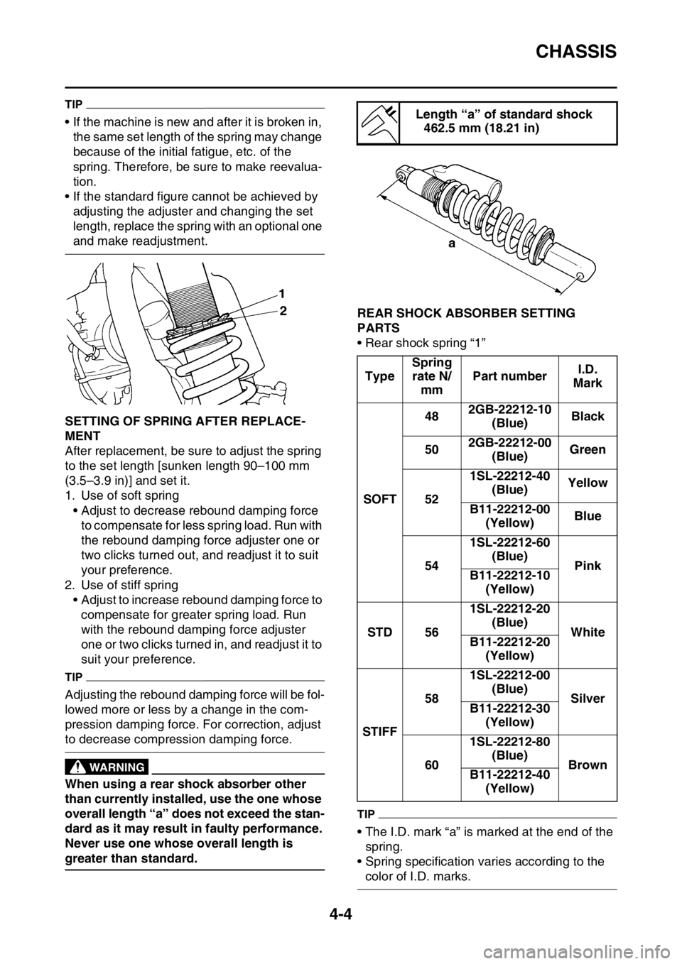
• Rear shock spring “1”
TIP
• The I.D. mark “a” is marked at the end of the spring.
• Spring specification varies according to the
color of I.D. marks.
Length “a” of standard shock 462.5 mm (18.21 in)
Type Spring
rate N/ mm Part number
I.D.
Mark
SOFT 48
2GB-22212-10
(Blue) Black
50 2GB-22212-00
(Blue) Green
52 1SL-22212-40
(Blue) Yellow
B11-22212-00 (Yellow) Blue
54 1SL-22212-60
(Blue) Pink
B11-22212-10
(Yellow)
STD 56 1SL-22212-20
(Blue) White
B11-22212-20
(Yellow)
STIFF 58
1SL-22212-00
(Blue) Silver
B11-22212-30
(Yellow)
60 1SL-22212-80
(Blue) Brown
B11-22212-40
(Yellow)
Page 241 of 426
CAMSHAFT
6-14
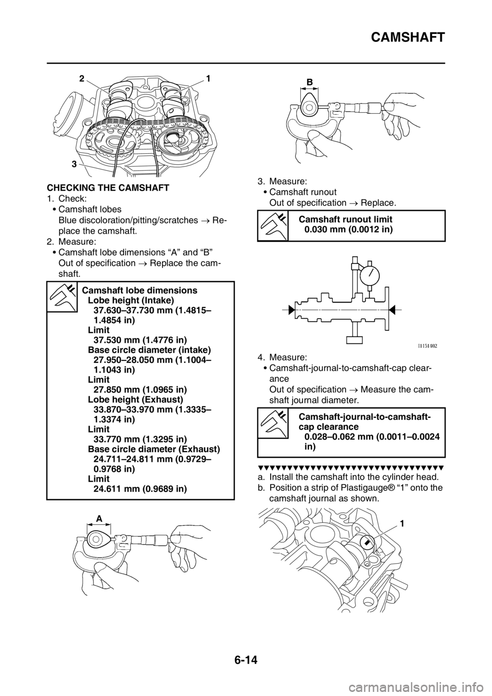
EAS2GC1239CHECKING THE CAMSHAFT
1. Check:• Camshaft lobes
Blue discoloration/pitting/scratches Re-
place the camshaft.
2. Measure:
• Camshaft lobe dimensions “A” and “B”Out of specification Replace the cam-
shaft. 3. Measure:
• Camshaft runout
Out of specification Replace.
4. Measure: • Camshaft-journal-to-camshaft-cap clear-ance
Out of specification Measure the cam-
shaft journal diameter.
▼▼▼▼▼▼▼▼▼▼▼▼▼▼▼▼▼▼▼▼▼▼▼▼▼▼▼▼▼▼▼▼
a. Install the camshaft into the cylinder head.
b. Position a strip of Plastigauge® “1” onto the camshaft journal as shown.
Camshaft lobe dimensions
Lobe height (Intake)37.630–37.730 mm (1.4815–
1.4854 in)
Limit 37.530 mm (1.4776 in)
Base circle diameter (intake) 27.950–28.050 mm (1.1004–
1.1043 in)
Limit 27.850 mm (1.0965 in)
Lobe height (Exhaust) 33.870–33.970 mm (1.3335–
1.3374 in)
Limit 33.770 mm (1.3295 in)
Base circle diameter (Exhaust) 24.711–24.811 mm (0.9729–
0.9768 in)
Limit 24.611 mm (0.9689 in)
1
2
3
Camshaft runout limit 0.030 mm (0.0012 in)
Camshaft-journal-to-camshaft-
cap clearance 0.028–0.062 mm (0.0011–0.0024
in)
1
Page 254 of 426
VALVES AND VALVE SPRINGS
6-27
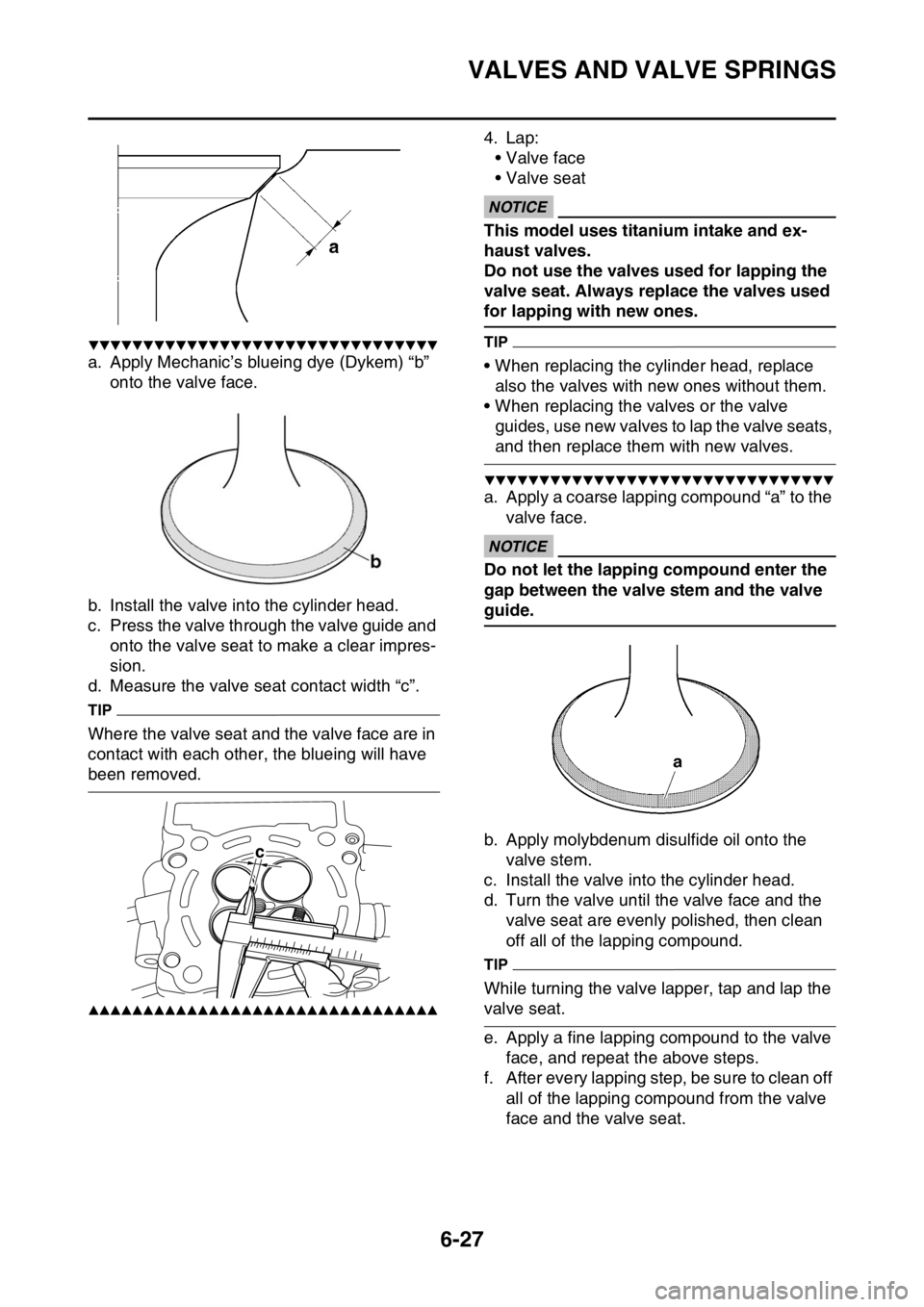
▼▼▼▼▼▼▼▼▼▼▼▼▼▼▼▼▼▼▼▼▼▼▼▼▼▼▼▼▼▼▼▼
a. Apply Mechanic’s blueing dye (Dykem) “b” onto the valve face.
b. Install the valve into the cylinder head.
c. Press the valve through the valve guide and onto the valve seat to make a clear impres-
sion.
d. Measure the valve seat contact width “c”.
TIP
Where the valve seat and the valve face are in
contact with each other, the blueing will have
been removed.
▲▲▲▲▲▲▲▲▲▲▲▲▲▲▲▲▲▲▲▲▲▲▲▲▲▲▲▲▲▲▲▲
4. Lap:
• Valve face
• Valve seat
ECA
NOTICE
This model uses titanium intake and ex-
haust valves.
Do not use the valves used for lapping the
valve seat. Always replace the valves used
for lapping with new ones.
TIP
• When replacing the cylinder head, replace also the valves with new ones without them.
• When replacing the valves or the valve guides, use new valves to lap the valve seats,
and then replace them with new valves.
▼▼▼▼▼▼▼▼▼▼▼▼▼▼▼▼▼▼▼▼▼▼▼▼▼▼▼▼▼▼▼▼
a. Apply a coarse lapping compound “a” to the
valve face.
ECA
NOTICE
Do not let the lapping compound enter the
gap between the valve stem and the valve
guide.
b. Apply molybdenum disulfide oil onto the valve stem.
c. Install the valve into the cylinder head.
d. Turn the valve until the valve face and the valve seat are evenly polished, then clean
off all of the lapping compound.
TIP
While turning the valve lapper, tap and lap the
valve seat.
e. Apply a fine lapping co mpound to the valve
face, and repeat the above steps.
f. After every lapping step, be sure to clean off all of the lapping compound from the valve
face and the valve seat.
c
Page 255 of 426
VALVES AND VALVE SPRINGS
6-28
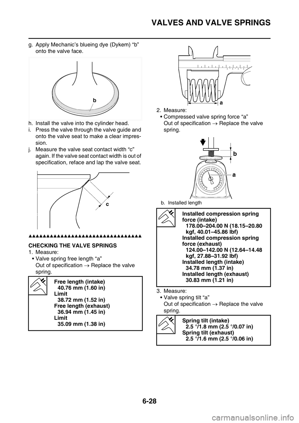
g. Apply Mechanic’s blueing dye (Dykem) “b” onto the valve face.
h. Install the valve into the cylinder head.
i. Press the valve through the valve guide and onto the valve seat to make a clear impres-
sion.
j. Measure the valve seat contact width “c” again. If the valve seat contact width is out of
specification, reface and lap the valve seat.
▲▲▲▲▲▲▲▲▲▲▲▲▲▲▲▲▲▲▲▲▲▲▲▲▲▲▲▲▲▲▲▲
EAS2GC1253CHECKING THE VALVE SPRINGS
1. Measure:
• Valve spring free length “a”Out of specification Replace the valve
spring. 2. Measure:
• Compressed valve spring force “a”
Out of specification Replace the valve
spring.
3. Measure: • Valve spring tilt “a”Out of specification Replace the valve
spring.
Free length (intake)
40.76 mm (1.60 in)
Limit 38.72 mm (1.52 in)
Free length (exhaust) 36.94 mm (1.45 in)
Limit 35.09 mm (1.38 in)
b. Installed length
Installed compression spring
force (intake) 178.00–204.00 N (18.15–20.80
kgf, 40.01–45.86 lbf)
Installed compression spring
force (exhaust) 124.00–142.00 N (12.64–14.48
kgf, 27.88–31.92 lbf)
Installed length (intake) 34.78 mm (1.37 in)
Installed length (exhaust) 30.83 mm (1.21 in)
Spring tilt (intake) 2.5 °/1.8 mm (2.5 °/0.07 in)
Spring tilt (exhaust) 2.5 °/1.6 mm (2.5 °/0.06 in)
Page 261 of 426
CYLINDER AND PISTON
6-34
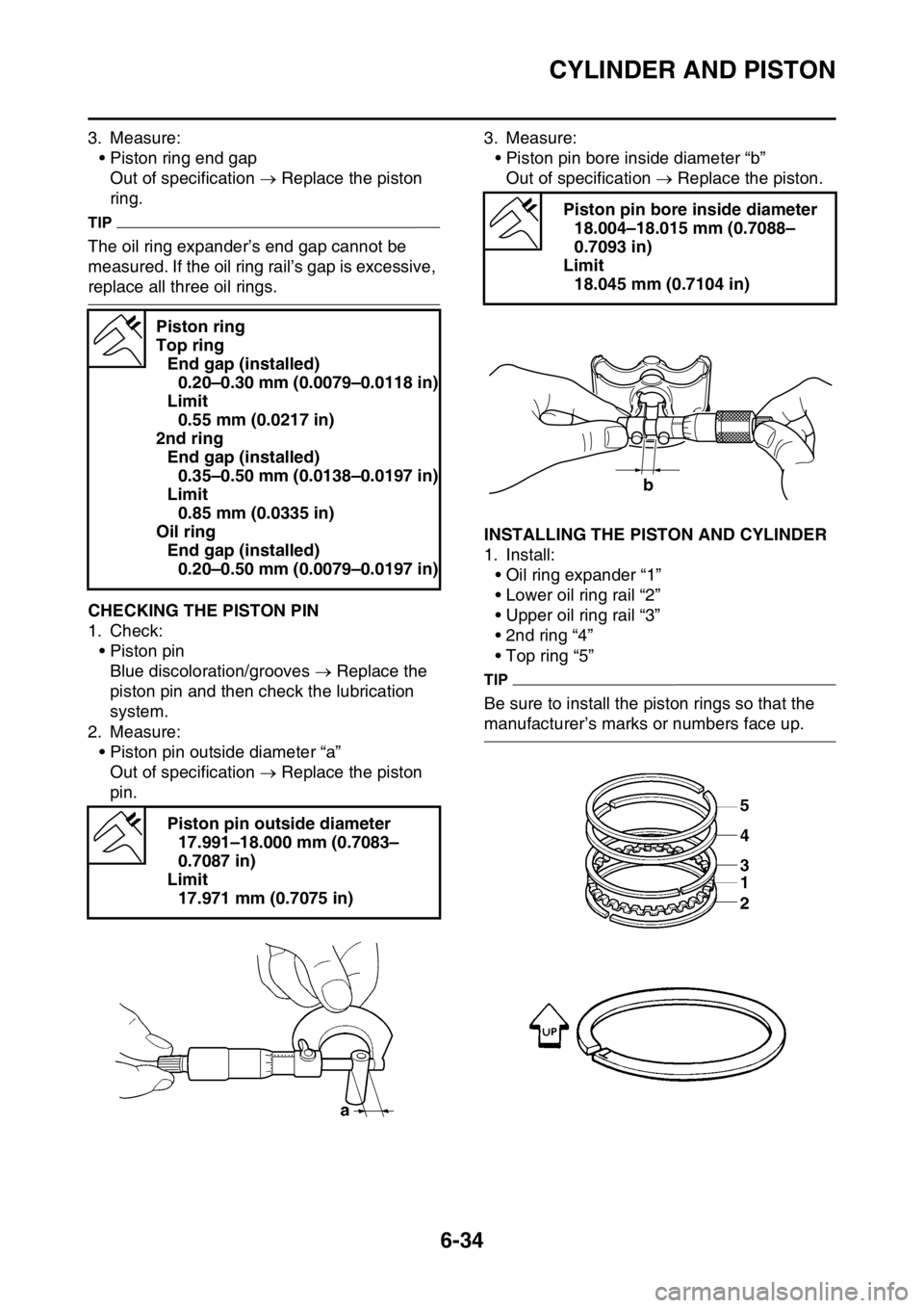
3. Measure:• Piston ring end gapOut of specification Replace the piston
ring.
TIP
The oil ring expander’s end gap cannot be
measured. If the oil ring ra il’s gap is excessive,
replace all three oil rings.
EAS2GC1260CHECKING THE PISTON PIN
1. Check:
• Piston pinBlue discoloration/grooves Replace the
piston pin and then check the lubrication
system.
2. Measure: • Piston pin outside diameter “a”
Out of specification Replace the piston
pin. 3. Measure:
• Piston pin bore inside diameter “b”Out of specification Replace the piston.
EAS2GC1261INSTALLING THE PISTON AND CYLINDER
1. Install:
• Oil ring expander “1”
• Lower oil ring rail “2”
• Upper oil ring rail “3”
• 2nd ring “4”
• Top ring “5”
TIP
Be sure to install the piston rings so that the
manufacturer’s marks or numbers face up.
Piston ring
Top ring
End gap (installed)0.20–0.30 mm (0.0079–0.0118 in)
Limit 0.55 mm (0.0217 in)
2nd ring End gap (installed)0.35–0.50 mm (0.0138–0.0197 in)
Limit 0.85 mm (0.0335 in)
Oil ring End gap (installed)0.20–0.50 mm (0.0079–0.0197 in)
Piston pin outside diameter 17.991–18.000 mm (0.7083–
0.7087 in)
Limit 17.971 mm (0.7075 in)
Piston pin bore inside diameter 18.004–18.015 mm (0.7088–
0.7093 in)
Limit 18.045 mm (0.7104 in)
b
Page 306 of 426
TRANSMISSION
6-79
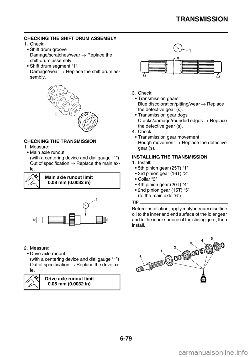
EAS2GC1325CHECKING THE SHIFT DRUM ASSEMBLY
1. Check:• Shift drum grooveDamage/scratches/wear Replace the
shift drum assembly.
• Shift drum segment “1” Damage/wear Replace the shift drum as-
sembly.
EAS2GC1326CHECKING THE TRANSMISSION
1. Measure: • Main axle runout(with a centering device and dial gauge “1”)
Out of specification Replace the main ax-
le.
2. Measure: • Drive axle runout(with a centering device and dial gauge “1”)
Out of specification Replace the drive ax-
le. 3. Check:
• Transmission gears
Blue discoloration/pitting/wear Replace
the defective gear (s).
• Transmission gear dogs
Cracks/damage/rounded edges Replace
the defective gear (s).
4. Check:
• Transmission gear movementRough movement Replace the defective
gear (s).
EAS2GC1327INSTALLING THE TRANSMISSION
1. Install:
• 5th pinion gear (25T) “1”
• 3rd pinion gear (16T) “2”
• Collar “3”
• 4th pinion gear (20T) “4”
• 2nd pinion gear (15T) “5”(to the main axle “6”)
TIP
Before installation, apply molybdenum disulfide
oil to the inner and end surface of the idler gear
and to the inner surface of the sliding gear, then
install.
Main axle runout limit
0.08 mm (0.0032 in)
Drive axle runout limit 0.08 mm (0.0032 in)
3 4
2
1
6
5
M
Page 366 of 426

FUEL INJECTION SYSTEM
9-36
2 Connection of wire harness ECU coupler.
Check the locking condition
of the coupler.
Disconnect the coupler and
check the pins (bent or bro-
ken terminals and locking
condition of the pins). Improperly connected
Connect the coupler securely
or repair/replace the wire har-
ness. Crank the engine.
Fault code number is not dis-
played
Service is finished.
Fault code number is dis-
played Go to item 3.
3 Wire harness continuity. Open or short circuit Re-
place the wire harness.
Between the crankshaft posi-
tion sensor coupler and ECU
coupler.
black/blue–black/blue
gray–gray Crank the engine.
Fault code number is not dis-
played
Service is finished.
Fault code number is dis-
played Go to item 4.
4 Installed condition of crank- shaft position sensor.
Check for looseness or
pinching.
Check the gap between the
crankshaft position sensor
and the pickup rotor. Improperly installed sensor
Reinstall or replace the
sensor.
Refer to “GENERATOR AND
STARTER CLUTCH” on
page 6-63. Crank the engine.
Fault code number is not dis-
played
Service is finished.
Fault code number is dis-
played Go to item 5.
5 Defective crankshaft position sensor. Check the crankshaft position
sensor.
Refer to “CHECKING THE
CRANKSHAFT POSITION
SENSOR” on page 9-74. Crank the engine.
Fault code number is not dis-
played
Service is finished.
Fault code number is dis-
played Go to item 6.
6 Malfunction in ECU. Replace the ECU. Fault code No. 12
Item Crankshaft position sensor: no normal signals are received
from the crankshaft position sensor.
Page 367 of 426

FUEL INJECTION SYSTEM
9-37
TIP
• If fault code Nos. 13 and 14 are both displayed, perform the checks and maintenance jobs for fault
code No. 13 first.
• Before troubleshooting, disconnect the star ter motor lead from the starter relay.
Fault code No. 13
Item Intake air pressure sensor: open or short circuit detected.
Fail-safe system Able to start engine
Able to drive vehicle
Diagnostic code No. 03
Diagnostic tool display Displays the intake air pressure.
Procedure Operate the throttle while pushing the start switch.(If the display
value changes, the performance is OK.)
Item Probable cause of malfunc-
tion and check Maintenance jobConfirmation of service
completion
1 Connection of intake air pres- sure sensor coupler.
Check the locking condition
of the coupler.
Disconnect the coupler and
check the pins (bent or bro-
ken terminals and locking
condition of the pins). Improperly connected
Connect the coupler securely
or repair/replace the wire har-
ness. Push the start switch.
Fault code number is not dis-
played
Service is finished.
Fault code number is dis-
played Go to item 2.
2 Connection of wire harness ECU coupler.
Check the locking condition
of the coupler.
Disconnect the coupler and
check the pins (bent or bro-
ken terminals and locking
condition of the pins). Improperly connected
Connect the coupler securely
or repair/replace the wire har-
ness. Push the start switch.
Fault code number is not dis-
played
Service is finished.
Fault code number is dis-
played Go to item 3.
3 Wire harness continuity. Open or short circuit Re-
place the wire harness.
Between intake air pressure
sensor coupler and ECU cou-
pler.
black/blue–black/blue
pink–pink
blue–blue Push the start switch.
Fault code number is not dis-
played
Service is finished.
Fault code number is dis-
played Go to item 4.
4 Installed condition of intake air pressure sensor.
Check for looseness or
pinching. Improperly installed sensor
Reinstall or replace the
sensor. Push the start switch.
Fault code number is not dis-
played
Service is finished.
Fault code number is dis-
played Go to item 5.