fault codes YAMAHA WR 450F 2016 Owners Manual
[x] Cancel search | Manufacturer: YAMAHA, Model Year: 2016, Model line: WR 450F, Model: YAMAHA WR 450F 2016Pages: 426, PDF Size: 10.86 MB
Page 362 of 426
FUEL INJECTION SYSTEM
9-32
EAS2GC1377YAMAHA DIAGNOSTIC TOOL
This model uses the Yamaha diagnostic tool to identify malfunctions.
For information about using the Yamaha diagnostic tool, refer to the operation manual that is included
with the tool.
FEATURES OF THE YAMAHA DIAGNOSTIC TOOL
A diagnosis can be made more quickly than traditional methods with the Yamaha diagnostic tool.
Using this software, ECU and sensor data, as well as fault diagnosis, vehicle maintenance, and any
necessary information can be recorded and disp layed on your computer screen through a USB
adapter connected to the computer interface with a communication cable connected to the vehicle’s
ECU.
Data obtained in various functions can be saved as vehicle history, and can be accumulated.
FUNCTIONS OF THE YAMAHA DIAGNOSTIC TOOL
However, the diagnostic tool cannot be used to freely change the basic vehicle functions, such as
adjusting the ignition timing.
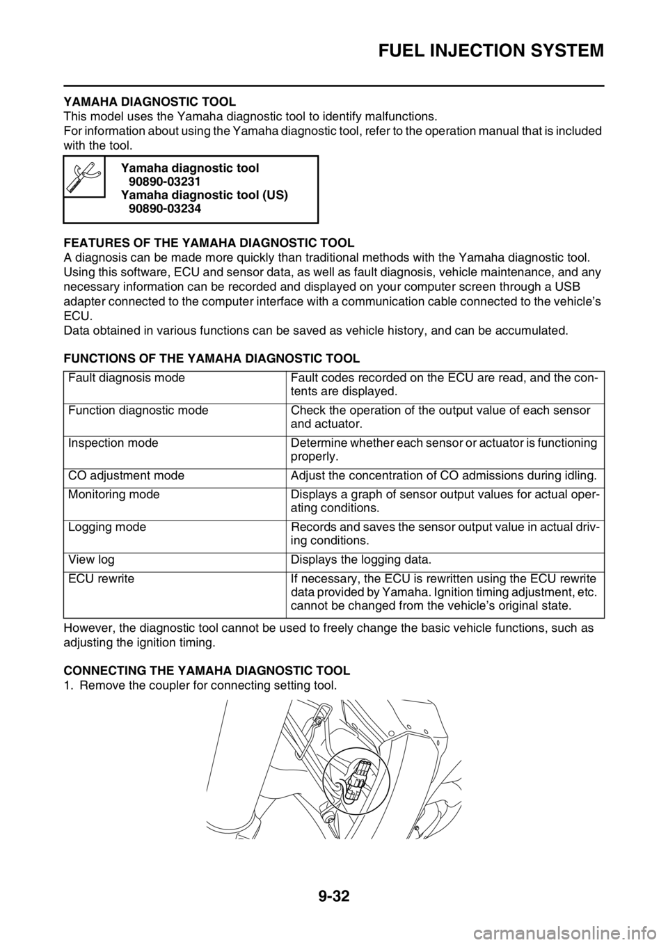
CONNECTING THE YAMAHA DIAGNOSTIC TOOL
1. Remove the coupler for connecting setting tool. Yamaha diagnostic tool
90890-03231
Yamaha diagnostic tool (US) 90890-03234
Fault diagnosis mode Fault codes recorded on the ECU are read, and the con- tents are displayed.
Function diagnostic mode Check the operation of the output value of each sensor
and actuator.
Inspection mode Determine whether each s ensor or actuator is functioning
properly.
CO adjustment mode Adjust the concentration of CO admissions during idling.
Monitoring mode Displays a graph of sensor output values for actual oper-
ating conditions.
Logging mode Records and saves the sensor output value in actual driv-
ing conditions.
View log Displays the logging data.
ECU rewrite If necessary, the ECU is rewritten using the ECU rewrite
data provided by Yamaha. Ignition timing adjustment, etc.
cannot be changed from the vehicle’s original state.
Page 365 of 426

FUEL INJECTION SYSTEM
9-35
6. ConditionThe current conditions are displayed. (Detected/Recovered)
7. Symptom
The symptoms of the detected malfunction are displayed.
8. Diagnosis code The diagnosis codes related to the detected malfunction are displayed.
9. FFD (only for models that can display freeze frame data) The mark “ ” is displayed when the freeze frame data is available.
10.ECU conduction time (hour: minute: second)
The total ECU conduction time (total hours the vehicle’s start switch was ON) when the malfunc-
tion was detected is displayed.
11.Number of main switch operation after detection
The number of times the meter light comes on by pushing the start switch between the malfunction
detection and code reading is displayed.
12.Number of occurrences The number of malfunction occurrences between th e malfunction detection and code reading is
displayed.
EAS2GC1378TROUBLESHOOTING DETAILS
This section describes the measures per fault c ode number displayed on the diagnostic tool. Check
and service the items or components that are the probable cause of the malfunction following the or-
der given.
After the check and service of the malfunctioning part have been completed, reset the diagnostic tool
display according to the reinstatement method.
Fault code No.:
Fault code number displayed on the diagnostic tool when the engine failed to work normally.
Diagnostic code No.:
Diagnostic code number to be used when the diagnostic mode is operated.
Fault code No. 12
Item Crankshaft position sensor: no normal signals are received
from the crankshaft position sensor.
Fail-safe system Unable to start engine
Unable to drive vehicle
Diagnostic code No. —
Diagnostic tool display —
Procedure —
Item Probable cause of malfunc-
tion and check Maintenance jobConfirmation of service
completion
1 Connection of crankshaft po- sition sensor coupler.
Check the locking condition
of the coupler.
Disconnect the coupler and
check the pins (bent or bro-
ken terminals and locking
condition of the pins). Improperly connected
Connect the coupler securely
or repair/replace the wire har-
ness. Crank the engine.
Fault code number is not dis-
played
Service is finished.
Fault code number is dis-
played Go to item 2.
Page 418 of 426

LIST OF SELF-DIAGNOSTIC AND FAIL-SAFE ACTIONS
10-5
EAS2GC1425
LIST OF SELF-DIAGNOSTIC AND FAIL-SAFE ACTIONS
LIST OF DIAGNOSTIC CODES
COMMUNICATION ERROR WITH YAMAHA DIAGNOSTIC TOOLFault
code Item Page
12 Crankshaft position sensor: no normal signals are received from the crankshaft position sensor. 9-35
13 Intake air pressure sensor: open or short circuit detected. 9-37
14 Intake air pressure sensor: hose system malfunction (clogged or de- tached hose) 9-38
15 Throttle position sensor: open or short circuit detected. 9-39
16 Throttle position sensor: stuck throttle position sensor is detected. 9-41
21 Coolant temperature sensor: open or short circuit detected. 9-42
22 Intake air temperature sensor: open or short circuit detected. 9-43
30 Latch up detected. 9-44
33 Ignition coil: open or short circuit detected in the primary lead of the ignition coil. 9-45
39 Injector: open or short circuit detected. 9-47
41 Lean angle sensor: open or short circuit detected. 9-48
43 Fuel system voltage: incorrect voltage supplied to the fuel injector and fuel pump. 9-49
44 EEPROM fault code number: an error is detected while reading or writing on EEPROM. 9-50
46 Charging voltage is abnormal. 9-51
50 Faulty ECU memory. (When this malfunction is detected in the ECU, the fault code number might not appear on the meter.) 9-52
Fault code Item Page
Waiting
for con-
nection No communication signal is received from the ECU.
9-52
Er-2 Signals from the ECU cannot be re ceived within the specified period
of time. 9-53
Er-3 Data from the ECU cannot be received correctly. 9-54
Er-4 Registered data cannot be received from the Yamaha diagnostic tool. 9-55