width YAMAHA WR 450F 2016 Owners Manual
[x] Cancel search | Manufacturer: YAMAHA, Model Year: 2016, Model line: WR 450F, Model: YAMAHA WR 450F 2016Pages: 426, PDF Size: 10.86 MB
Page 52 of 426

GENERAL SPECIFICATIONS
2-1
EAS2GC1061
GENERAL SPECIFICATIONS
ModelModel 2GC1 (USA) 2GC2 (CAN)
2GC3 (EUR)
2GC4, 2GC5 (AUS) (NZL) (ZAF)
DimensionsOverall length 2165 mm (85.2 in)
Overall width 825 mm (32.5 in)
Overall height 1280 mm (50.4 in)
Seat height 965 mm (38.0 in)
Wheelbase 1465 mm (57.7 in)
Ground clearance 325 mm (12.80 in)
WeightCurb weight 123 kg (271 lb)
Page 53 of 426

ENGINE SPECIFICATIONS
2-2
EAS2GC1062
ENGINE SPECIFICATIONS
EngineEngine type Liquid cooled 4-stroke, DOHC
Displacement 449 cm
3
Number of cylinders Single cylinder
Bore stroke 97.0 60.8 mm (3.82 2.39 in)
Compression ratio 12.5:1
Starting system Electric starter and kickstarter
Fuel
Recommended fuel Premium unleaded gasoline only
Fuel tank capacity 7.5 L (2.0 US gal, 1.7 Imp.gal)
Fuel reserve amount 2.0 L (0.5 US gal, 0.4 Imp.gal)
Engine oilLubrication system Wet sump
Recommended brand YAMALUBE
Type SAE 10W-40, SAE 10W-50, SAE 15W-40, SAE 20W-40 or SAE 20W-50
Recommended engine oil grade API service SG type or higher, JASO standard MA
Engine oil quantity
Quantity (disassembled) 0.95 L (1.00 US qt, 0.84 Imp.qt)
Oil change 0.67 L (0.71 US qt, 0.59 Imp.qt)
With oil filter removal 0.69 L (0.73 US qt, 0.61 Imp.qt)
Oil filterOil filter type Paper
Bypass valve opening pressure 40.0–80.0 kPa (0.40–0.80 kgf/cm
2,
5.8–11.6 psi)
Oil pump Oil pump type Trochoid
Inner-rotor-to-outer-rotor-tip clear ance 0.000–0.150 mm (0.0000–0.0059 in)
Limit 0.20 mm (0.0079 in)
Outer-rotor-to-oil-pump-housing clearance 0.13–0.18 mm (0.0051–0.0071 in)
Limit 0.24 mm (0.0094 in)
Oil-pump-housing-to -inner-and-outer-rotor
clearance 0.06–0.11 mm (0.0024–0.0043 in)
Limit 0.17 mm (0.0067 in)
Cooling system
Radiator (including all routes) 1.03 L (1.09 US qt, 0.91 Imp.qt)
Radiator capacity 0.57 L (0.60 US qt, 0.50 Imp.qt)
Radiator cap valve opening pressure 107.9–137.3 kPa (1.08–1.37 kg/cm
2,
15.6–19.9 psi)
Radiator core Width 112.6 mm (4.43 in)
Height 235.0 mm (9.25 in)
Depth 28.0 mm (1.10 in)
Water pump
Water pump type Single suction centrifugal pump
Spark plug(s)Manufacturer/model NGK/CR8E
Spark plug gap 0.7–0.8 mm (0.028–0.031 in)
Page 54 of 426

ENGINE SPECIFICATIONS
2-3
Cylinder headCombustion chamber volume 25.98–26.78 cm3 (1.59–1.63 cu.in)
Warpage limit 0.05 mm (0.0020 in)
Camshaft Drive system Chain drive (left)
Camshaft cap inside diameter 22.000–22.021 mm (0.8661–0.8670 in)
Camshaft journal diameter 21.959–21.972 mm (0.8645–0.8650 in)
Camshaft-journal-to-camshaft-cap cl earance 0.028–0.062 mm (0.0011–0.0024 in)
Camshaft lobe dimensions
Lobe height (Intake) 37.630–37.730 mm (1.4815–1.4854 in)
Limit 37.530 mm (1.4776 in)
Base circle diameter (intake) 27.950–28.050 mm (1.1004–1.1043 in)
Limit 27.850 mm (1.0965 in)
Lobe height (Exhaust) 33.870–33.970 mm (1.3335–1.3374 in)
Limit 33.770 mm (1.3295 in)
Base circle diameter (Exhaust) 24.711–24.811 mm (0.9729–0.9768 in)
Limit 24.611 mm (0.9689 in)
Camshaft runout limit 0.030 mm (0.0012 in)
Timing chain Tensioning system Automatic
Valve, valve seat, valve guide
Valve clearance (cold) Intake 0.13–0.20 mm (0.0051–0.0079 in)
Exhaust 0.18–0.25 mm (0.0071–0.0098 in)
Valve dimensions
Valve head diameter (intake) 36.90–37.10 mm (1.4528–1.4606 in)
Valve head diameter (exhaust) 30.40–30.60 mm (1.1968–1.2047 in)
Valve face width (intake) 1.697 mm (0.0668 in)
Valve face width (exhaust) 1.768 mm (0.0696 in)
Valve seat contact width (intake) 0.90–1.10 mm (0.0354–0.0433 in)
Valve seat contact width (exhaust) 0.90–1.10 mm (0.0354–0.0433 in)
Valve margin thickness (intake) 1.20 mm (0.0472 in)
Valve margin thickness (exhaust) 0.85 mm (0.0335 in)
Valve stem diameter (intake) 5.475–5.490 mm (0.2156–0.2161 in)
Limit 5.445 mm (0.2144 in)
Valve stem diameter (exhaust) 5.465–5.480 mm (0.2152–0.2157 in)
Limit 5.435 mm (0.2140 in)
Valve guide inside diameter (intake) 5.500–5.512 mm (0.2165–0.2170 in)
Limit 5.550 mm (0.2185 in)
Valve guide inside diameter (exhaus t) 5.500–5.512 mm (0.2165–0.2170 in)
Limit 5.550 mm (0.2185 in)
Valve-stem-to-valve-guide clearance (intake) 0.010–0.037 mm (0.0004–0.0015 in)
Limit 0.080 mm (0.0032 in)
Valve-stem-to-valve-guide clearance (exhaust) 0.020–0.047 mm (0.0008–0.0019 in)
Limit 0.100 mm (0.0039 in)
Valve stem runout 0.010 mm (0.0004 in)
Page 56 of 426

ENGINE SPECIFICATIONS
2-5
CrankshaftCrank assembly width 61.93–62.00 mm (2.438–2.441 in)
Runout limit 0.030 mm (0.0012 in)
Big end side clearance 0.150–0.450 mm (0.0059–0.0177 in)
BalancerBalancer drive method Gear
ClutchClutch type Wet, multiple-disc
Clutch release method Inner push, cam push
Clutch lever free play 7.0–12.0 mm (0.28–0.47 in)
Friction plate 1 thickness 2.92–3.08 mm (0.115–0.121 in)
Wear limit 2.85 mm (0.112 in)
Plate quantity 3 pcs
Friction plate 2 thickness 2.92–3.08 mm (0.115–0.121 in)
Wear limit 2.85 mm (0.112 in)
Plate quantity 5 pcs
Clutch plate 1 thickness 1.90–2.10 mm (0.075–0.083 in)
Plate quantity 4 pcs
Warpage limit 0.10 mm (0.004 in)
Clutch plate 2 thickness 1.50–1.70 mm (0.059–0.067 in)
Plate quantity 3 pcs
Warpage limit 0.10 mm (0.004 in)
Clutch spring free length 50.00 mm (1.97 in)
Limit 47.50 mm (1.87 in)
Spring quantity 6 pcs
Push rod bending limit 0.10 mm (0.004 in)
TransmissionTransmission type Constant mesh 5-speed
Primary reduction system Spur gear
Primary reduction ratio 2.609 (60/23)
Final drive Chain
Secondary reduction ratio 3.846 (50/13)
Operation Left foot operation
Gear ratio
1st 2.417 (29/12)
2nd 1.733 (26/15)
3rd 1.313 (21/16)
4th 1.050 (21/20)
5th 0.840 (21/25)
Main axle runout limit 0.08 mm (0.0032 in)
Drive axle runout limit 0.08 mm (0.0032 in)
Shifting mechanism
Shift mechanism type Shift drum and guide bar
Shift fork guide bar bending limit 0.050 mm (0.0020 in)
Shift fork thickness 4.85 mm (0.1909 in)
Decompression deviceDevice type Auto decomp
Air filterAir filter element Wet element
Air filter oil grade Yamaha foam air filter oil or other quality foam air filter oil
Page 242 of 426
CAMSHAFT
6-15
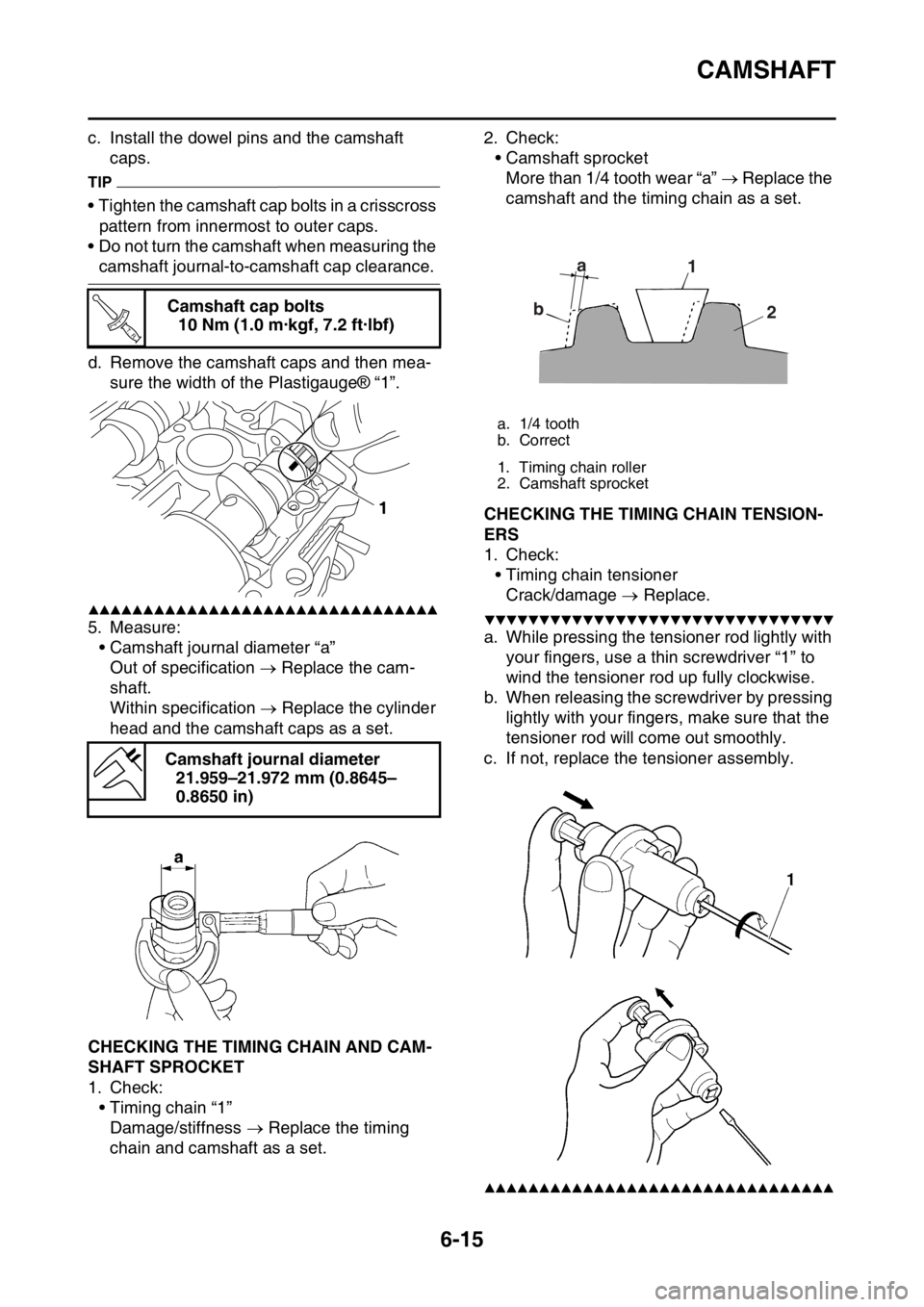
c. Install the dowel pins and the camshaft caps.
TIP
• Tighten the camshaft cap bolts in a crisscross pattern from innermost to outer caps.
• Do not turn the camshaft when measuring the
camshaft journal-to-camshaft cap clearance.
d. Remove the camshaft caps and then mea- sure the width of the Plastigauge® “1”.
▲▲▲▲▲▲▲▲▲▲▲▲▲▲▲▲▲▲▲▲▲▲▲▲▲▲▲▲▲▲▲▲
5. Measure:• Camshaft journal diameter “a”Out of specification Replace the cam-
shaft.
Within specification Replace the cylinder
head and the camshaft caps as a set.
EAS2GC1240CHECKING THE TIMING CHAIN AND CAM-
SHAFT SPROCKET
1. Check: • Timing chain “1”
Damage/stiffness Replace the timing
chain and camshaft as a set. 2. Check:
• Camshaft sprocketMore than 1/4 tooth wear “a” Replace the
camshaft and the timing chain as a set.
EAS2GC1241CHECKING THE TIMING CHAIN TENSION-
ERS
1. Check: • Timing chain tensioner
Crack/damage Replace.
▼▼▼▼▼▼▼▼▼▼▼▼▼▼▼▼▼▼▼▼▼▼▼▼▼▼▼▼▼▼▼▼
a. While pressing the tensioner rod lightly with
your fingers, use a thin screwdriver “1” to
wind the tensioner rod up fully clockwise.
b. When releasing the screwdriver by pressing lightly with your fingers, make sure that the
tensioner rod will come out smoothly.
c. If not, replace the tensioner assembly.
▲▲▲▲▲▲▲▲▲▲▲▲▲▲▲▲▲▲▲▲▲▲▲▲▲▲▲▲▲▲▲▲
Camshaft cap bolts 10 Nm (1.0 m·kgf, 7.2 ft·lbf)
Camshaft journal diameter 21.959–21.972 mm (0.8645–
0.8650 in)
T R..
1
a. 1/4 tooth
b. Correct
1. Timing chain roller
2. Camshaft sprocket
a
b 1
2
Page 251 of 426
VALVES AND VALVE SPRINGS
6-24
EAS2GC1250REMOVING THE VALVES
TIP
Before removing the internal parts of the cylin-
der head (e.g., valves, valve springs, valve
seats), make sure that the valves are properly
sealed.
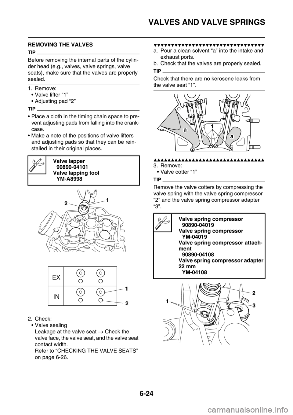
1. Remove:• Valve lifter “1”
• Adjusting pad “2”
TIP
• Place a cloth in the timing chain space to pre-vent adjusting pads from falling into the crank-
case.
• Make a note of the positions of valve lifters and adjusting pads so that they can be rein-
stalled in their original places.
2. Check: • Valve sealingLeakage at the valve seat Check the
valve face, the valve seat, and the valve seat
contact width.
Refer to “CHECKING THE VALVE SEATS”
on page 6-26.
▼▼▼▼▼▼▼▼▼▼▼▼▼▼▼▼▼▼▼▼▼▼▼▼▼▼▼▼▼▼▼▼
a. Pour a clean solvent “a” into the intake and exhaust ports.
b. Check that the valves are properly sealed.
TIP
Check that there are no kerosene leaks from
the valve seat “1”.
▲▲▲▲▲▲▲▲▲▲▲▲▲▲▲▲▲▲▲▲▲▲▲▲▲▲▲▲▲▲▲▲
3. Remove: • Valve cotter “1”
TIP
Remove the valve cotters by compressing the
valve spring with the valve spring compressor
“2” and the valve spring compressor adapter
“3”.
Valve lapper
90890-04101
Valve lapping tool YM-A8998
1
2
Valve spring compressor
90890-04019
Valve spring compressor YM-04019
Valve spring compressor attach-
ment 90890-04108
Valve spring compressor adapter
22 mm YM-04108
a 1
a
Page 253 of 426
VALVES AND VALVE SPRINGS
6-26
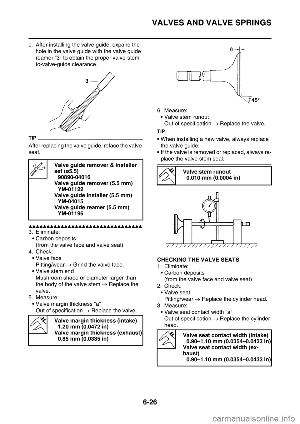
c. After installing the valve guide, expand the hole in the valve guide with the valve guide
reamer “3” to obtain the proper valve-stem-
to-valve-guide clearance.
TIP
After replacing the valve guide, reface the valve
seat.
▲▲▲▲▲▲▲▲▲▲▲▲▲▲▲▲▲▲▲▲▲▲▲▲▲▲▲▲▲▲▲▲
3. Eliminate:• Carbon deposits(from the valve face and valve seat)
4. Check: • Valve facePitting/wear Grind the valve face.
• Valve stem end Mushroom shape or diameter larger than
the body of the valve stem Replace the
valve.
5. Measure: • Valve margin thickness “a”
Out of specification Replace the valve. 6. Measure:
• Valve stem runout
Out of specification Replace the valve.
TIP
• When installing a new valve, always replace
the valve guide.
• If the valve is removed or replaced, always re-
place the valve stem seal.
EAS2GC1252CHECKING THE VALVE SEATS
1. Eliminate: • Carbon deposits(from the valve face and valve seat)
2. Check: • Valve seatPitting/wear Replace the cylinder head.
3. Measure: • Valve seat contact width “a”Out of specification Replace the cylinder
head.
Valve guide remover & installer
set (ø5.5)
90890-04016
Valve guide remover (5.5 mm) YM-01122
Valve guide installer (5.5 mm) YM-04015
Valve guide reamer (5.5 mm) YM-01196
Valve margin thickness (intake) 1.20 mm (0.0472 in)
Valve margin thickness (exhaust) 0.85 mm (0.0335 in)
Valve stem runout 0.010 mm (0.0004 in)
Valve seat contact width (intake) 0.90–1.10 mm (0.0354–0.0433 in)
Valve seat contact width (ex-
haust) 0.90–1.10 mm (0.0354–0.0433 in)
Page 254 of 426
VALVES AND VALVE SPRINGS
6-27
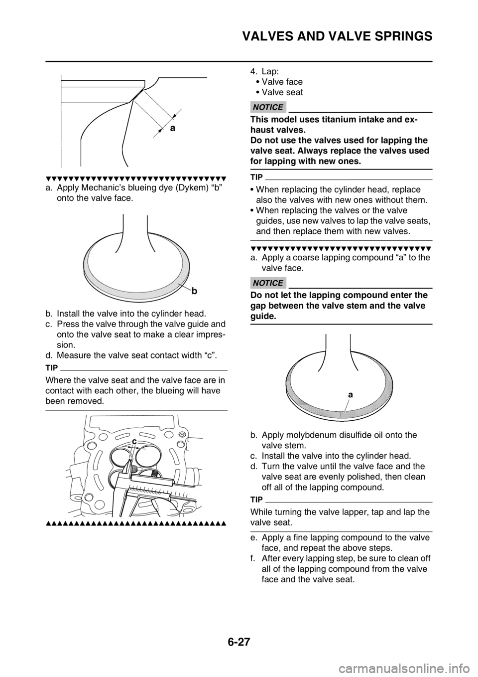
▼▼▼▼▼▼▼▼▼▼▼▼▼▼▼▼▼▼▼▼▼▼▼▼▼▼▼▼▼▼▼▼
a. Apply Mechanic’s blueing dye (Dykem) “b” onto the valve face.
b. Install the valve into the cylinder head.
c. Press the valve through the valve guide and onto the valve seat to make a clear impres-
sion.
d. Measure the valve seat contact width “c”.
TIP
Where the valve seat and the valve face are in
contact with each other, the blueing will have
been removed.
▲▲▲▲▲▲▲▲▲▲▲▲▲▲▲▲▲▲▲▲▲▲▲▲▲▲▲▲▲▲▲▲
4. Lap:
• Valve face
• Valve seat
ECA
NOTICE
This model uses titanium intake and ex-
haust valves.
Do not use the valves used for lapping the
valve seat. Always replace the valves used
for lapping with new ones.
TIP
• When replacing the cylinder head, replace also the valves with new ones without them.
• When replacing the valves or the valve guides, use new valves to lap the valve seats,
and then replace them with new valves.
▼▼▼▼▼▼▼▼▼▼▼▼▼▼▼▼▼▼▼▼▼▼▼▼▼▼▼▼▼▼▼▼
a. Apply a coarse lapping compound “a” to the
valve face.
ECA
NOTICE
Do not let the lapping compound enter the
gap between the valve stem and the valve
guide.
b. Apply molybdenum disulfide oil onto the valve stem.
c. Install the valve into the cylinder head.
d. Turn the valve until the valve face and the valve seat are evenly polished, then clean
off all of the lapping compound.
TIP
While turning the valve lapper, tap and lap the
valve seat.
e. Apply a fine lapping co mpound to the valve
face, and repeat the above steps.
f. After every lapping step, be sure to clean off all of the lapping compound from the valve
face and the valve seat.
c
Page 255 of 426
VALVES AND VALVE SPRINGS
6-28
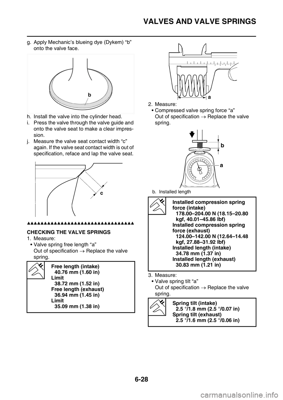
g. Apply Mechanic’s blueing dye (Dykem) “b” onto the valve face.
h. Install the valve into the cylinder head.
i. Press the valve through the valve guide and onto the valve seat to make a clear impres-
sion.
j. Measure the valve seat contact width “c” again. If the valve seat contact width is out of
specification, reface and lap the valve seat.
▲▲▲▲▲▲▲▲▲▲▲▲▲▲▲▲▲▲▲▲▲▲▲▲▲▲▲▲▲▲▲▲
EAS2GC1253CHECKING THE VALVE SPRINGS
1. Measure:
• Valve spring free length “a”Out of specification Replace the valve
spring. 2. Measure:
• Compressed valve spring force “a”
Out of specification Replace the valve
spring.
3. Measure: • Valve spring tilt “a”Out of specification Replace the valve
spring.
Free length (intake)
40.76 mm (1.60 in)
Limit 38.72 mm (1.52 in)
Free length (exhaust) 36.94 mm (1.45 in)
Limit 35.09 mm (1.38 in)
b. Installed length
Installed compression spring
force (intake) 178.00–204.00 N (18.15–20.80
kgf, 40.01–45.86 lbf)
Installed compression spring
force (exhaust) 124.00–142.00 N (12.64–14.48
kgf, 27.88–31.92 lbf)
Installed length (intake) 34.78 mm (1.37 in)
Installed length (exhaust) 30.83 mm (1.21 in)
Spring tilt (intake) 2.5 °/1.8 mm (2.5 °/0.07 in)
Spring tilt (exhaust) 2.5 °/1.6 mm (2.5 °/0.06 in)
Page 302 of 426
CRANKSHAFT ASSEMBLY AND BALANCER SHAFT
6-75
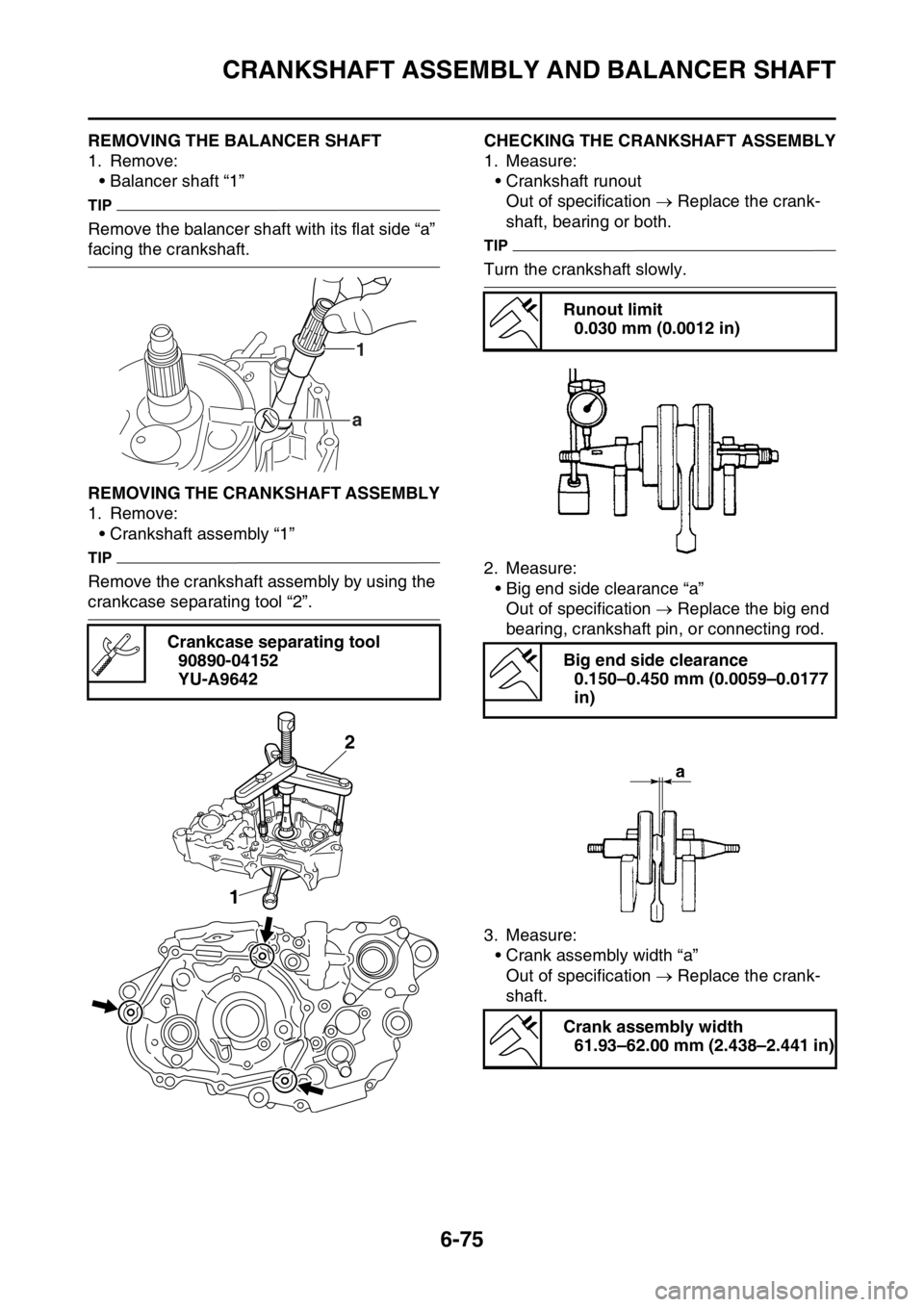
EAS2GC1318REMOVING THE BALANCER SHAFT
1. Remove:• Balancer shaft “1”
TIP
Remove the balancer shaft with its flat side “a”
facing the crankshaft.
EAS2GC1319REMOVING THE CRANKSHAFT ASSEMBLY
1. Remove:• Crankshaft assembly “1”
TIP
Remove the crankshaft assembly by using the
crankcase separating tool “2”.
EAS2GC1320CHECKING THE CRANKSHAFT ASSEMBLY
1. Measure:• Crankshaft runoutOut of specification Replace the crank-
shaft, bearing or both.
TIP
Turn the crankshaft slowly.
2. Measure: • Big end side clearance “a”Out of specification Replace the big end
bearing, crankshaft pin, or connecting rod.
3. Measure: • Crank assembly width “a”Out of specification Replace the crank-
shaft.
Crankcase separating tool
90890-04152
YU-A9642
1
a
2
1
Runout limit 0.030 mm (0.0012 in)
Big end side clearance 0.150–0.450 mm (0.0059–0.0177
in)
Crank assembly width 61.93–62.00 mm (2.438–2.441 in)