YAMAHA XJ6-N 2010 Owner's Manual
Manufacturer: YAMAHA, Model Year: 2010, Model line: XJ6-N, Model: YAMAHA XJ6-N 2010Pages: 104, PDF Size: 2.86 MB
Page 21 of 104
INSTRUMENT AND CONTROL FUNCTIONS
3-6
3
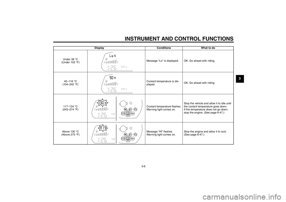
DisplayConditionsWhat to do
Under 39 °C
(Under 103 °F) Message “Lo” is displayed. OK. Go ahead with riding.
40–116 °C
(104–242 °F) Coolant temperature is dis-
played.
OK. Go ahead with riding.
117–134 °C
(243–274 °F) Coolant temperature flashes.
Warning light comes on.Stop the vehicle and allow it to idle until
the coolant temperature goes down.
If the temperature does not go down,
stop the engine. (See page 6-47.)
Above 135 °C
(Above 275 °F) Message “HI” flashes.
Warning light comes on.Stop the engine and allow it to cool.
(See page 6-47.)
ABSABS
U20SE3E0.book Page 6 Monday, April 23, 2012 10:47 AM
Page 22 of 104
INSTRUMENT AND CONTROL FUNCTIONS
3-7
3
EAU11534
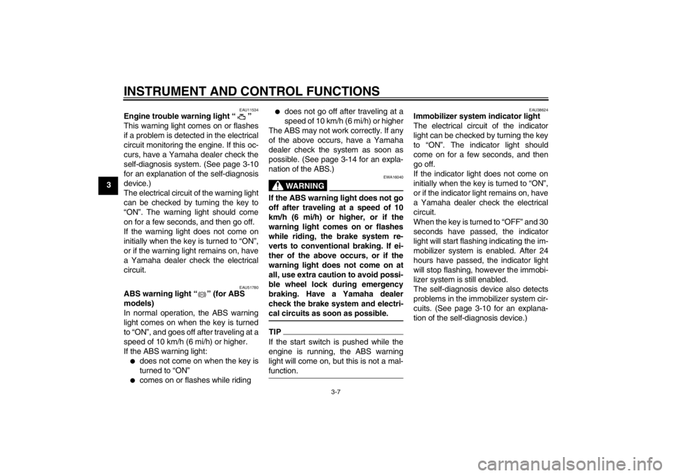
Engine trouble warning light “ ”
This warning light comes on or flashes
if a problem is detected in the electrical
circuit monitoring the engine. If this oc-
curs, have a Yamaha dealer check the
self-diagnosis system. (See page 3-10
for an explanation of the self-diagnosis
device.)
The electrical circuit of the warning light
can be checked by turning the key to
“ON”. The warning light should come
on for a few seconds, and then go off.
If the warning light does not come on
initially when the key is turned to “ON”,
or if the warning light remains on, have
a Yamaha dealer check the electrical
circuit.
EAU51780
ABS warning light “ ” (for ABS
models)
In normal operation, the ABS warning
light comes on when the key is turned
to “ON”, and goes off after traveling at a
speed of 10 km/h (6 mi/h) or higher.
If the ABS warning light:●
does not come on when the key is
turned to “ON”
●
comes on or flashes while riding
●
does not go off after traveling at a
speed of 10 km/h (6 mi/h) or higher
The ABS may not work correctly. If any
of the above occurs, have a Yamaha
dealer check the system as soon as
possible. (See page 3-14 for an expla-
nation of the ABS.)WARNING
EWA16040
If the ABS warning light does not go
off after traveling at a speed of 10
km/h (6 mi/h) or higher, or if the
warning light comes on or flashes
while riding, the brake system re-
verts to conventional braking. If ei-
ther of the above occurs, or if the
warning light does not come on at
all, use extra caution to avoid possi-
ble wheel lock during emergency
braking. Have a Yamaha dealer
check the brake system and electri-
cal circuits as soon as possible.TIPIf the start switch is pushed while the
engine is running, the ABS warning
light will come on, but this is not a mal-
function.
EAU38624
Immobilizer system indicator light
The electrical circuit of the indicator
light can be checked by turning the key
to “ON”. The indicator light should
come on for a few seconds, and then
go off.
If the indicator light does not come on
initially when the key is turned to “ON”,
or if the indicator light remains on, have
a Yamaha dealer check the electrical
circuit.
When the key is turned to “OFF” and 30
seconds have passed, the indicator
light will start flashing indicating the im-
mobilizer system is enabled. After 24
hours have passed, the indicator light
will stop flashing, however the immobi-
lizer system is still enabled.
The self-diagnosis device also detects
problems in the immobilizer system cir-
cuits. (See page 3-10 for an explana-
tion of the self-diagnosis device.)
ABS
U20SE3E0.book Page 7 Monday, April 23, 2012 10:47 AM
Page 23 of 104
INSTRUMENT AND CONTROL FUNCTIONS
3-8
3
EAU46765
Multi-function meter unit
WARNING
EWA12422
Be sure to stop the vehicle before
making any setting changes to the
multi-function meter unit. Changing
settings while riding can distract the
operator and increase the risk of an
accident.
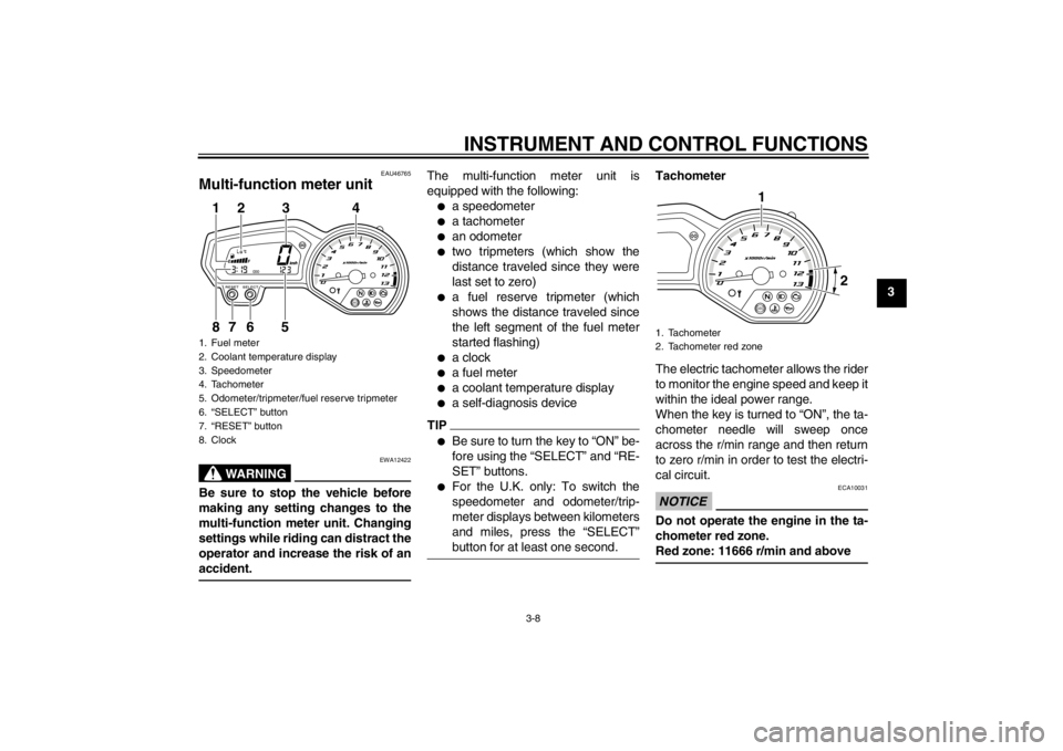
The multi-function meter unit is
equipped with the following:●
a speedometer
●
a tachometer
●
an odometer
●
two tripmeters (which show the
distance traveled since they were
last set to zero)
●
a fuel reserve tripmeter (which
shows the distance traveled since
the left segment of the fuel meter
started flashing)
●
a clock
●
a fuel meter
●
a coolant temperature display
●
a self-diagnosis device
TIP●
Be sure to turn the key to “ON” be-
fore using the “SELECT” and “RE-
SET” buttons.
●
For the U.K. only: To switch the
speedometer and odometer/trip-
meter displays between kilometers
and miles, press the “SELECT”
button for at least one second.
Tachometer
The electric tachometer allows the rider
to monitor the engine speed and keep it
within the ideal power range.
When the key is turned to “ON”, the ta-
chometer needle will sweep once
across the r/min range and then return
to zero r/min in order to test the electri-
cal circuit.NOTICE
ECA10031
Do not operate the engine in the ta-
chometer red zone.
Red zone: 11666 r/min and above
1. Fuel meter
2. Coolant temperature display
3. Speedometer
4. Tachometer
5. Odometer/tripmeter/fuel reserve tripmeter
6. “SELECT” button
7. “RESET” button
8. Clock
ABS
1
8
2
3
4
7
6
5
1. Tachometer
2. Tachometer red zone
ABS1 2
U20SE3E0.book Page 8 Monday, April 23, 2012 10:47 AM
Page 24 of 104
INSTRUMENT AND CONTROL FUNCTIONS
3-9
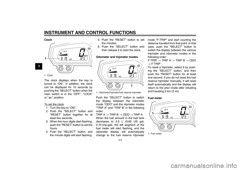
3Clock
The clock displays when the key is
turned to “ON”. In addition, the clock
can be displayed for 10 seconds by
pushing the “SELECT” button when the
main switch is in the “OFF”, “LOCK”
or “ ” position.
To set the clock
1. Turn the key to “ON”.
2. Push the “SELECT” button and
“RESET” button together for at
least two seconds.
3. When the hour digits start flashing, push the “RESET” button to set the
hours.
4. Push the “SELECT” button, and the minute digits will start flashing. 5. Push the “RESET” button to set
the minutes.
6. Push the “SELECT” button and then release it to start the clock.
Odometer and tripmeter modes
Push the “SELECT” button to switch
the display between the odometer
mode “ODO” and the tripmeter modes
“TRIP A” and “TRIP B” in the following
order:
TRIP A → TRIP B → ODO → TRIP A
When the fuel amount in the fuel tank
decreases to 3.2 L (0.85 US gal,
0.70 Imp.gal), the left segment of the
fuel meter will start flashing, and the
odometer display will automatically
change to the fuel reserve tripmeter mode “F-TRIP” and start counting the
distance traveled from that point. In that
case, push the “SELECT” button to
switch the display between the various
tripmeter and odometer modes in the
following order:
F-TRIP
→ TRIP A → TRIP B → ODO
→ F-TRIP
To reset a tripmeter, select it by push-
ing the “SELECT” button, and then
push the “RESET” button for at least
one second. If you do not reset the fuel
reserve tripmeter manually, it will reset
itself automatically and the display will
return to the prior mode after refueling
and traveling 5 km (3 mi).
Fuel meter1. Clock1
1. Odometer/tripmeter/fuel reserve tripmeter
1
1. Fuel meter
1
U20SE3E0.book Page 9 Monday, April 23, 2012 10:47 AM
Page 25 of 104
INSTRUMENT AND CONTROL FUNCTIONS
3-10
3
The fuel meter indicates the amount of
fuel in the fuel tank. The display seg-
ments of the fuel meter disappear to-
wards “E” (Empty) as the fuel level
decreases. When the last segment on
the left starts flashing, refuel as soon as
possible.
TIPThis fuel meter is equipped with a self-
diagnosis system. If a problem is de-
tected in the electrical circuit, the follow-
ing cycle is repeated until the
malfunction is corrected: fuel level seg-
ments and symbol “ ” flash eight
times, then go off for approximately 3
seconds. If this occurs, have a Yamaha
dealer check the electrical circuit.
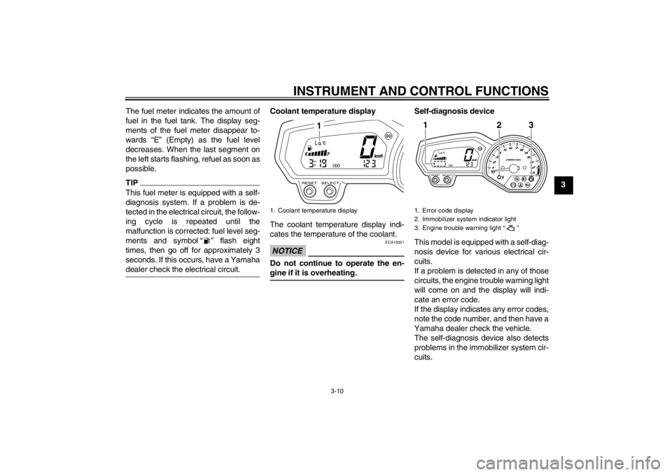
Coolant temperature display
The coolant temperature display indi-
cates the temperature of the coolant.NOTICE
ECA10021
Do not continue to operate the en-
gine if it is overheating.
Self-diagnosis device
This model is equipped with a self-diag-
nosis device for various electrical cir-
cuits.
If a problem is detected in any of those
circuits, the engine trouble warning light
will come on and the display will indi-
cate an error code.
If the display indicates any error codes,
note the code number, and then have a
Yamaha dealer check the vehicle.
The self-diagnosis device also detects
problems in the immobilizer system cir-
cuits.
1. Coolant temperature display
1
1. Error code display
2. Immobilizer system indicator light
3. Engine trouble warning light “ ”
ABS
1
2
3
U20SE3E0.book Page 10 Monday, April 23, 2012 10:47 AM
Page 26 of 104
INSTRUMENT AND CONTROL FUNCTIONS
3-11
3If a problem is detected in the immobi-
lizer system circuits, the immobilizer
system indicator light will flash and the
display will indicate an error code.
TIPIf the display indicates error code 52,
this could be caused by transponder in-
terference. If this error code appears,
try the following.1. Use the code re-registering key to
start the engine.TIPMake sure there are no other immobi-
lizer keys close to the main switch, and
do not keep more than one immobilizer
key on the same key ring! Immobilizer
system keys may cause signal interfer-
ence, which may prevent the engine
from starting.2. If the engine starts, turn it off andtry starting the engine with the
standard keys.
3. If one or both of the standard keys do not start the engine, take the
vehicle, the code re-registering key and both standard keys to a
Yamaha dealer and have the stan-
dard keys re-registered.
NOTICE
ECA11590
If the display indicates an error
code, the vehicle should be checked
as soon as possible in order to avoid
engine damage.
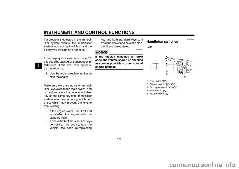
EAU1234A
Handlebar switches Left1. Pass switch “ ”
2. Dimmer switch “ / ”
3. Turn signal switch “ / ”
4. Horn switch “ ”
5. Hazard switch “ ”
U20SE3E0.book Page 11 Monday, April 23, 2012 10:47 AM
Page 27 of 104
INSTRUMENT AND CONTROL FUNCTIONS
3-12
3
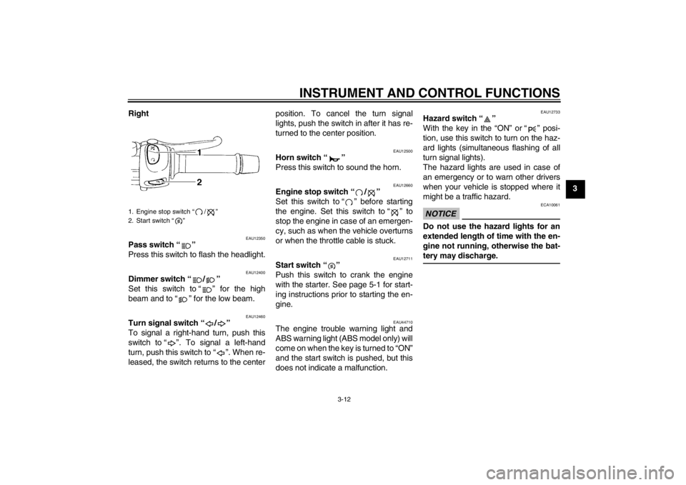
Right
EAU12350
Pass switch “ ”
Press this switch to flash the headlight.
EAU12400
Dimmer switch “ / ”
Set this switch to “ ” for the high
beam and to “ ” for the low beam.
EAU12460
Turn signal switch “ / ”
To signal a right-hand turn, push this
switch to “ ”. To signal a left-hand
turn, push this switch to “ ”. When re-
leased, the switch returns to the center position. To cancel the turn signal
lights, push the switch in after it has re-
turned to the center position.
EAU12500
Horn switch “ ”
Press this switch to sound the horn.
EAU12660
Engine stop switch “ / ”
Set this switch to “ ” before starting
the engine. Set this switch to “ ” to
stop the engine in case of an emergen-
cy, such as when the vehicle overturns
or when the throttle cable is stuck.
EAU12711
Start switch “ ”
Push this switch to crank the engine
with the starter. See page 5-1 for start-
ing instructions prior to starting the en-
gine.
EAU44710
The engine trouble warning light and
ABS warning light (ABS model only) will
come on when the key is turned to “ON”
and the start switch is pushed, but this
does not indicate a malfunction.
EAU12733
Hazard switch “ ”
With the key in the “ON” or “ ” posi-
tion, use this switch to turn on the haz-
ard lights (simultaneous flashing of all
turn signal lights).
The hazard lights are used in case of
an emergency or to warn other drivers
when your vehicle is stopped where it
might be a traffic hazard.NOTICE
ECA10061
Do not use the hazard lights for an
extended length of time with the en-
gine not running, otherwise the bat-
tery may discharge.
1. Engine stop switch “ / ”
2. Start switch “ ”
U20SE3E0.book Page 12 Monday, April 23, 2012 10:47 AM
Page 28 of 104
INSTRUMENT AND CONTROL FUNCTIONS
3-13
3
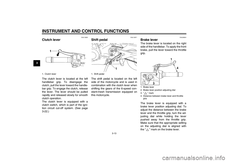
EAU12820
Clutch lever The clutch lever is located at the left
handlebar grip. To disengage the
clutch, pull the lever toward the handle-
bar grip. To engage the clutch, release
the lever. The lever should be pulled
rapidly and released slowly for smooth
clutch operation.
The clutch lever is equipped with a
clutch switch, which is part of the igni-
tion circuit cut-off system. (See page
3-22.)
EAU12871
Shift pedal The shift pedal is located on the left
side of the motorcycle and is used in
combination with the clutch lever when
shifting the gears of the 6-speed con-
stant-mesh transmission equipped on
this motorcycle.
EAU26824
Brake lever The brake lever is located on the right
side of the handlebar. To apply the front
brake, pull the lever toward the throttle
grip.
The brake lever is equipped with a
brake lever position adjusting dial. To
adjust the distance between the brake
lever and the throttle grip, turn the ad-
justing dial while holding the lever
pushed away from the throttle grip.
Make sure that the appropriate setting
on the adjusting dial is aligned with
the “ ” mark on the brake lever.
1. Clutch lever
1. Shift pedal
1
1. Brake lever
2. Brake lever position adjusting dial
3. “ ” mark
4. Distance between brake lever and throttle grip
U20SE3E0.book Page 13 Monday, April 23, 2012 10:47 AM
Page 29 of 104
INSTRUMENT AND CONTROL FUNCTIONS
3-14
3
EAU12941
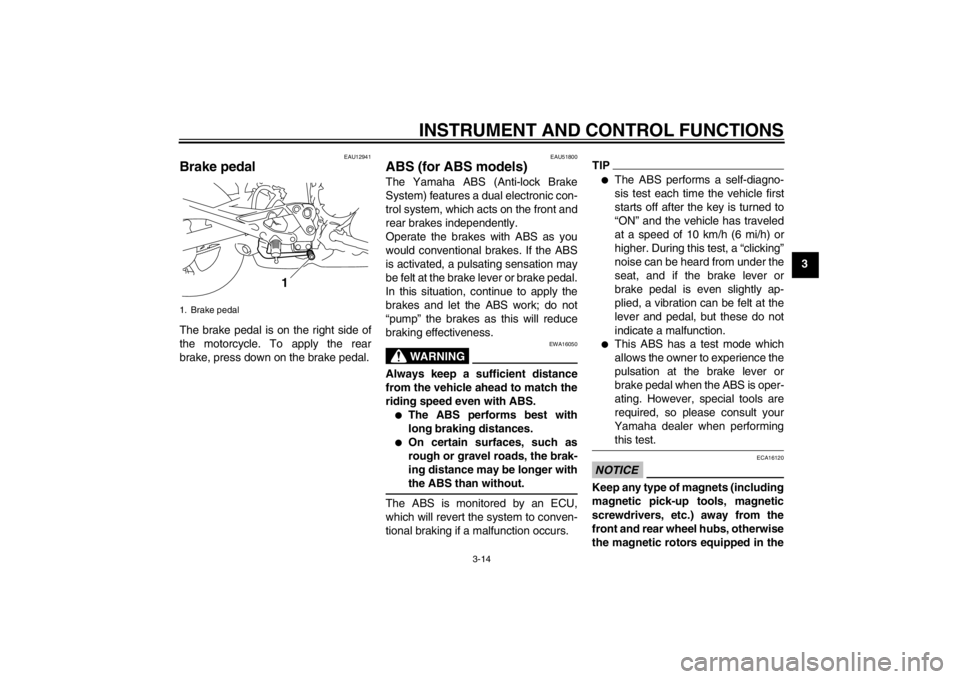
Brake pedal The brake pedal is on the right side of
the motorcycle. To apply the rear
brake, press down on the brake pedal.
EAU51800
ABS (for ABS models) The Yamaha ABS (Anti-lock Brake
System) features a dual electronic con-
trol system, which acts on the front and
rear brakes independently.
Operate the brakes with ABS as you
would conventional brakes. If the ABS
is activated, a pulsating sensation may
be felt at the brake lever or brake pedal.
In this situation, continue to apply the
brakes and let the ABS work; do not
“pump” the brakes as this will reduce
braking effectiveness.
WARNING
EWA16050
Always keep a sufficient distance
from the vehicle ahead to match the
riding speed even with ABS.●
The ABS performs best with
long braking distances.
●
On certain surfaces, such as
rough or gravel roads, the brak-
ing distance may be longer with
the ABS than without.
The ABS is monitored by an ECU,
which will revert the system to conven-
tional braking if a malfunction occurs.
TIP●
The ABS performs a self-diagno-
sis test each time the vehicle first
starts off after the key is turned to
“ON” and the vehicle has traveled
at a speed of 10 km/h (6 mi/h) or
higher. During this test, a “clicking”
noise can be heard from under the
seat, and if the brake lever or
brake pedal is even slightly ap-
plied, a vibration can be felt at the
lever and pedal, but these do not
indicate a malfunction.
●
This ABS has a test mode which
allows the owner to experience the
pulsation at the brake lever or
brake pedal when the ABS is oper-
ating. However, special tools are
required, so please consult your
Yamaha dealer when performing this test.
NOTICE
ECA16120
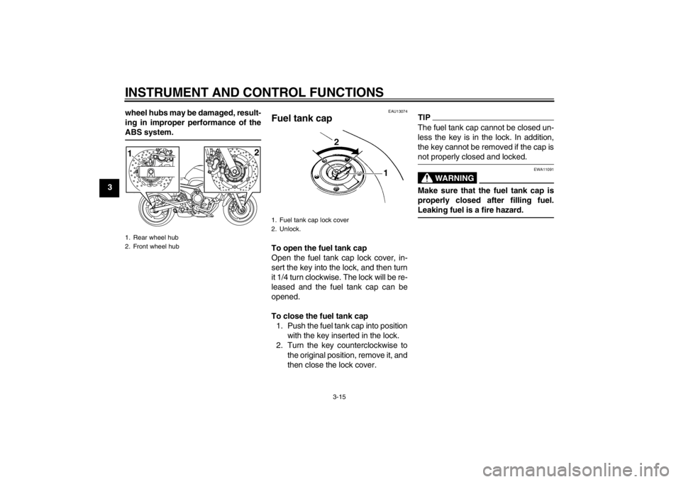
Keep any type of magnets (including
magnetic pick-up tools, magnetic
screwdrivers, etc.) away from the
front and rear wheel hubs, otherwise
the magnetic rotors equipped in the
1. Brake pedal
1
U20SE3E0.book Page 14 Monday, April 23, 2012 10:47 AM
Page 30 of 104
INSTRUMENT AND CONTROL FUNCTIONS
3-15
3wheel hubs may be damaged, result-
ing in improper performance of the
ABS system.
EAU13074
Fuel tank cap To open the fuel tank cap
Open the fuel tank cap lock cover, in-
sert the key into the lock, and then turn
it 1/4 turn clockwise. The lock will be re-
leased and the fuel tank cap can be
opened.
To close the fuel tank cap
1. Push the fuel tank cap into position with the key inserted in the lock.
2. Turn the key counterclockwise to the original position, remove it, and
then close the lock cover.
TIPThe fuel tank cap cannot be closed un-
less the key is in the lock. In addition,
the key cannot be removed if the cap is
not properly closed and locked.
WARNING
EWA11091
Make sure that the fuel tank cap is
properly closed after filling fuel.
Leaking fuel is a fire hazard.
1. Rear wheel hub
2. Front wheel hub1
2
1. Fuel tank cap lock cover
2. Unlock.
U20SE3E0.book Page 15 Monday, April 23, 2012 10:47 AM