YAMAHA XJR 1300 2003 Owners Manual
Manufacturer: YAMAHA, Model Year: 2003, Model line: XJR 1300, Model: YAMAHA XJR 1300 2003Pages: 102, PDF Size: 5.89 MB
Page 91 of 102
SPECIFICATIONS
8-2
8
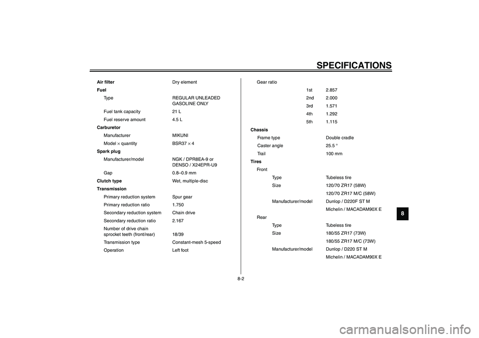
Air filterDry element
Fuel
Type REGULAR UNLEADED
GASOLINE ONLY
Fuel tank capacity 21 L
Fuel reserve amount 4.5 L
Carburetor
Manufacturer MIKUNI
Model × quantity BSR37 × 4
Spark plug
Manufacturer/model NGK / DPR8EA-9 or
DENSO / X24EPR-U9
Gap 0.8–0.9 mm
Clutch typeWet, multiple-disc
Transmission
Primary reduction system Spur gear
Primary reduction ratio 1.750
Secondary reduction system Chain drive
Secondary reduction ratio 2.167
Number of drive chain
sprocket teeth (front/rear) 18/39
Transmission type Constant-mesh 5-speed
Operation Left footGear ratio
1st 2.857
2nd 2.000
3rd 1.571
4th 1.292
5th 1.115
Chassis
Frame type Double cradle
Caster angle 25.5 °
Trail 100 mm
Tires
Front
Type Tubeless tire
Size 120/70 ZR17 (58W)
120/70 ZR17 M/C (58W)
Manufacturer/model Dunlop / D220F ST M
Michelin / MACADAM90X E
Rear
Type Tubeless tire
Size 180/55 ZR17 (73W)
180/55 ZR17 M/C (73W)
Manufacturer/model Dunlop / D220 ST M
Michelin / MACADAM90X E
U5WME0.book Page 2 Monday, July 29, 2002 10:25 AM
Page 92 of 102
SPECIFICATIONS
8-3
8
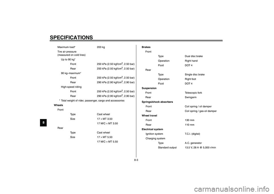
Maximum load* 203 kg
Tire air pressure
(measured on cold tires)
Up to 90 kg*
Front 250 kPa (2.50 kgf/cm
2, 2.50 bar)
Rear 250 kPa (2.50 kgf/cm2, 2.50 bar)
90 kg–maximum*
Front 250 kPa (2.50 kgf/cm2, 2.50 bar)
Rear 290 kPa (2.90 kgf/cm2, 2.90 bar)
High-speed riding
Front 250 kPa (2.50 kgf/cm2, 2.50 bar)
Rear 290 kPa (2.90 kgf/cm2, 2.90 bar)
* Total weight of rider, passenger, cargo and accessories
Wheels
Front
Type Cast wheel
Size 17 × MT 3.50
17 M/C × MT 3.50
Rear
Type Cast wheel
Size 17 × MT 5.50
17 M/C × MT 5.50Brakes
Front
Type Dual disc brake
Operation Right hand
Fluid DOT 4
Rear
Type Single disc brake
Operation Right foot
Fluid DOT 4
Suspension
Front Telescopic fork
Rear Swingarm
Springs/shock absorbers
Front Coil spring / oil damper
Rear Coil spring / gas-oil damper
Wheel travel
Front 130 mm
Rear 110 mm
Electrical system
Ignition system T.C.I. (digital)
Charging system
Type A.C. generator
Standard output 13.5 V, 28 A @ 5,000 r/min
U5WME0.book Page 3 Monday, July 29, 2002 10:25 AM
Page 93 of 102
SPECIFICATIONS
8-4
8
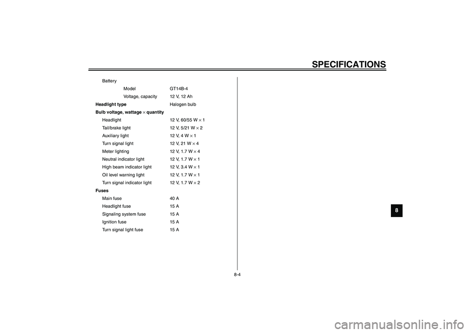
Battery
Model GT14B-4
Voltage, capacity 12 V, 12 Ah
Headlight typeHalogen bulb
Bulb voltage, wattage × quantity
Headlight 12 V, 60/55 W × 1
Tail/brake light 12 V, 5/21 W × 2
Auxiliary light 12 V, 4 W × 1
Turn signal light 12 V, 21 W × 4
Meter lighting 12 V, 1.7 W × 4
Neutral indicator light 12 V, 1.7 W × 1
High beam indicator light 12 V, 3.4 W × 1
Oil level warning light 12 V, 1.7 W × 1
Turn signal indicator light 12 V, 1.7 W × 2
Fuses
Main fuse 40 A
Headlight fuse 15 A
Signaling system fuse 15 A
Ignition fuse 15 A
Turn signal light fuse 15 A
U5WME0.book Page 4 Monday, July 29, 2002 10:25 AM
Page 94 of 102
SPECIFICATIONS
8-5
8
EAU04513
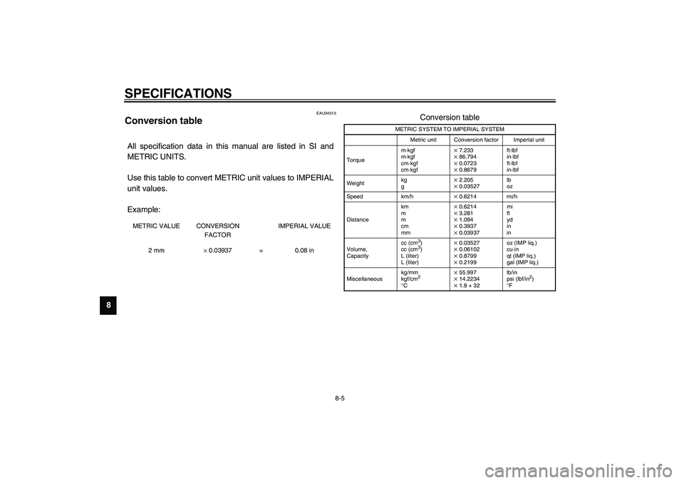
Conversion table CS-04EAll specification data in this manual are listed in SI and
METRIC UNITS.
Use this table to convert METRIC unit values to IMPERIAL
unit values.
Example:METRIC VALUE CONVERSION
FACTORIMPERIAL VALUE
2 mm× 0.03937 = 0.08 in
Conversion table
METRIC SYSTEM TO IMPERIAL SYSTEM
Metric unit Conversion factor Imperial unit
Torquem·kgf
m·kgf
cm·kgf
cm·kgf
× 7.233× 86.794× 0.0723× 0.8679ft·lbf
in·lbf
ft·lbf
in·lbf
Weightkg
g× 2.205× 0.03527lb
oz
Speed km/h× 0.6214 mi/h
Distancekm
m
m
cm
mm× 0.6214× 3.281× 1.094× 0.3937× 0.03937mi
ft
yd
in
in
Volume,
Capacitycc (cm
3)
cc (cm3)
L (liter)
L (liter)
× 0.03527× 0.06102× 0.8799× 0.2199oz (IMP liq.)
cu·in
qt (IMP liq.)
gal (IMP liq.)
Miscellaneouskg/mm
kgf/cm
2
°
C
× 55.997× 14.2234× 1.8 + 32 lb/in
psi (lbf/in
2)
°
F
U5WME0.book Page 5 Monday, July 29, 2002 10:25 AM
Page 95 of 102
CONSUMER INFORMATION
9
Identification numbers ....................................................................... 9-1
Key identification number .................................................................. 9-1
Vehicle identification number ............................................................. 9-1
Model label ........................................................................................ 9-2
U5WME0.book Page 1 Monday, July 29, 2002 10:25 AM
Page 96 of 102
9-1
9
EAU01039
9-CONSUMER INFORMATION
EAU02944
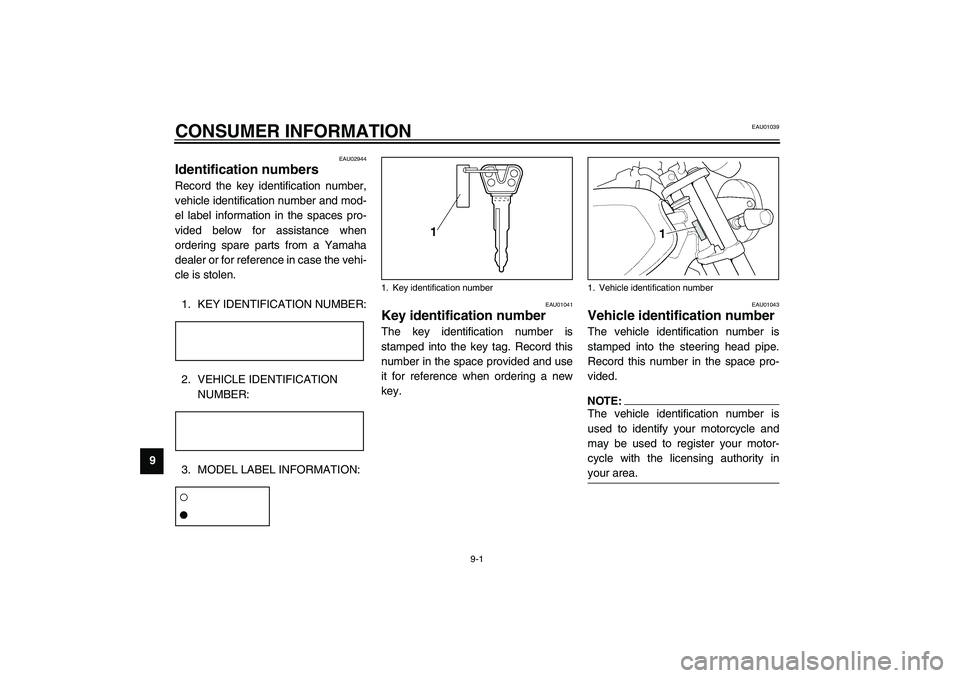
Identification numbers Record the key identification number,
vehicle identification number and mod-
el label information in the spaces pro-
vided below for assistance when
ordering spare parts from a Yamaha
dealer or for reference in case the vehi-
cle is stolen.
1. KEY IDENTIFICATION NUMBER:CA-02E2. VEHICLE IDENTIFICATION
NUMBER:CA-02E3. MODEL LABEL INFORMATION:CA-01EEAU01041
Key identification number The key identification number is
stamped into the key tag. Record this
number in the space provided and use
it for reference when ordering a new
key.
EAU01043
Vehicle identification number The vehicle identification number is
stamped into the steering head pipe.
Record this number in the space pro-
vided.NOTE:_ The vehicle identification number is
used to identify your motorcycle and
may be used to register your motor-
cycle with the licensing authority in
your area. _
1. Key identification number
1. Vehicle identification number
U5WME0.book Page 1 Monday, July 29, 2002 10:25 AM
Page 97 of 102
CONSUMER INFORMATION
9-2
9
EAU01050
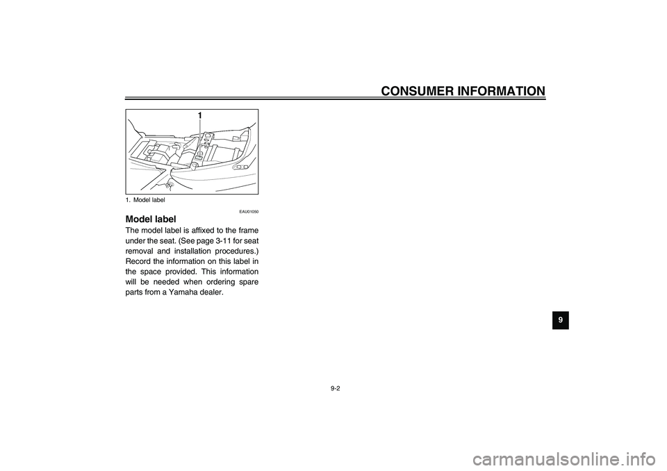
Model label The model label is affixed to the frame
under the seat. (See page 3-11 for seat
removal and installation procedures.)
Record the information on this label in
the space provided. This information
will be needed when ordering spare
parts from a Yamaha dealer.1. Model label
U5WME0.book Page 2 Monday, July 29, 2002 10:25 AM
Page 98 of 102

INDEXAAir filter element, cleaning ...................... 6-11
Anti-theft alarm ........................................3-4BBattery ................................................... 6-28
Brake and clutch fluid levels, checking ... 6-20
Brake and clutch fluids, changing........... 6-21
Brake and clutch levers, checking and
lubricating ............................................ 6-25
Brake and shift pedals, checking and
lubricating ............................................ 6-25
Brake lever...............................................3-7
Brake light switch (rear), adjusting ......... 6-19
Brake pads, checking............................. 6-19
Brake pedal..............................................3-7
Brake pedal position, adjusting .............. 6-18CCables, checking and lubricating............ 6-24
Carburetors, adjusting............................ 6-12
Care.........................................................7-1
Centerstand and sidestand,
checking and lubricating ...................... 6-25
Clutch lever ..............................................3-5
Clutch lever free play ............................. 6-17
Conversion table ......................................8-5DDimmer switch .........................................3-4
Drive chain, lubricating ........................... 6-23
Drive chain slack .................................... 6-22
Adjusting .......................................... 6-23
Checking .......................................... 6-22
EEngine break-in ....................................... 5-4
Engine idling speed ............................... 6-13
Engine oil and oil filter element ................ 6-7
Engine stop switch................................... 3-5FFront fork, adjusting ............................... 3-13
Front fork, checking ............................... 6-26
Fuel ......................................................... 3-9
Fuel cock ............................................... 3-10
Fuel consumption, tips for reducing ......... 5-4
Fuel gauge .............................................. 3-3
Fuel tank breather hose ......................... 3-10
Fuel tank cap ........................................... 3-8
Fuses, replacing .................................... 6-29HHandlebar switches ................................. 3-4
Hazard switch .......................................... 3-4
Headlight bulb, replacing ....................... 6-30
Helmet holder ........................................ 3-12
High beam indicator light ......................... 3-2
Horn switch ............................................. 3-4IIdentification numbers ............................. 9-1
Ignition circuit cut-off system.................. 3-17
Indicator and warning lights ..................... 3-2KKey identification number ........................ 9-1
LLight switch ..............................................3-5
Luggage strap holders ...........................3-16MMain switch/steering lock .........................3-1
Model label ..............................................9-2NNeutral indicator light ...............................3-2OOil level warning light ...............................3-2PPanel, removing and installing..................6-5
Parking.....................................................5-5
Part locations ...........................................2-1
Pass switch ..............................................3-4
Periodic maintenance and
lubrication chart .....................................6-2
Pre-operation check list ............................4-1SSafety information ....................................1-1
Seat .......................................................3-11
Shifting .....................................................5-3
Shift pedal ................................................3-6
Shift points (for Switzerland only) .............5-3
Shock absorber assemblies, adjusting ...3-15
Sidestand ...............................................3-17
Spark plugs, checking ..............................6-6
Specifications ...........................................8-1
Speedometer unit.....................................3-3
U5WME0.book Page 1 Monday, July 29, 2002 10:25 AM
Page 99 of 102

INDEX
Starter (choke) lever .............................. 3-11
Starting a cold engine .............................. 5-1
Starting a warm engine ............................ 5-2
Start switch .............................................. 3-5
Steering, checking ................................. 6-27
Storage.................................................... 7-4
Storage compartment ............................ 3-13TTachometer ............................................. 3-3
Tail/brake light bulb, replacing ............... 6-31
Throttle cable free play, adjusting .......... 6-13
Throttle grip and cable, checking and
lubricating............................................ 6-24
Tires ...................................................... 6-14
Tool kit..................................................... 6-1
Troubleshooting..................................... 6-36
Troubleshooting chart ............................ 6-37
Turn signal indicator lights ....................... 3-2
Turn signal light bulb, replacing ............. 6-31
Turn signal switch .................................... 3-4VValve clearance, adjusting ..................... 6-14
Vehicle identification number ................... 9-1WWheel bearings, checking...................... 6-27
Wheel (front).......................................... 6-32
Installing........................................... 6-33
Removing......................................... 6-32
Wheel (rear) .......................................... 6-34
Installing........................................... 6-35
Removing......................................... 6-34
Wheels .................................................. 6-17
U5WME0.book Page 2 Monday, July 29, 2002 10:25 AM
Page 100 of 102

Shiro.fm Page 1 Thursday, June 7, 2001 11:38 AM