ECO mode YAMAHA XMAX 125 2013 Owners Manual
[x] Cancel search | Manufacturer: YAMAHA, Model Year: 2013, Model line: XMAX 125, Model: YAMAHA XMAX 125 2013Pages: 96, PDF Size: 4.83 MB
Page 22 of 96
INSTRUMENT AND CONTROL FUNCTIONS
3-4
3
EAU49392
Indicator lights and warning
lights
EAU11030
Turn signal indicator lights “ ”
and “ ”
The corresponding indicator light flash-
es when the turn signal switch is
pushed to the left or right.
EAU11080
High beam indicator light “ ”
This indicator light comes on when the
high beam of the headlight is switched
on.
EAU43023
Engine trouble warning light “ ”
This warning light comes on if an elec-
trical circuit monitoring the engine is not
working correctly. If this occurs, have a
Yamaha dealer check the self-diagno-
sis system.
The electrical circuit of the warning light
can be checked by turning the key to
“ON”. The warning light should come
on for a few seconds, and then go off.
If the warning light does not come on
initially when the key is turned to “ON”,
or if the warning light remains on, have
a Yamaha dealer check the electrical
circuit.TIPThis warning light will come on when
the key is turned to “ON” and the start
switch is pushed, but this does not indi-
cate a malfunction.
EAU43032
ABS warning light “ ” (for ABS
models) NOTICE
ECA10831
If the ABS warning light comes on or
flashes while riding, the ABS may
not work correctly. If this occurs,
have a Yamaha dealer check the
electrical circuit.See page 3-13 for an explanation of the
ABS.
The electrical circuit of the warning light
can be checked by setting the engine
stop switch to “ ” and turning the key
to “ON”. The warning light should come
on for a few seconds, and then go off.
If the warning light does not come on
initially when the key is turned to “ON”,
or if the warning light remains on, have
a Yamaha dealer check the electrical
circuit.
WARNING
EWA11350
When the ABS warning light comes
on or flashes while riding, the brake
system reverts to conventional brak-
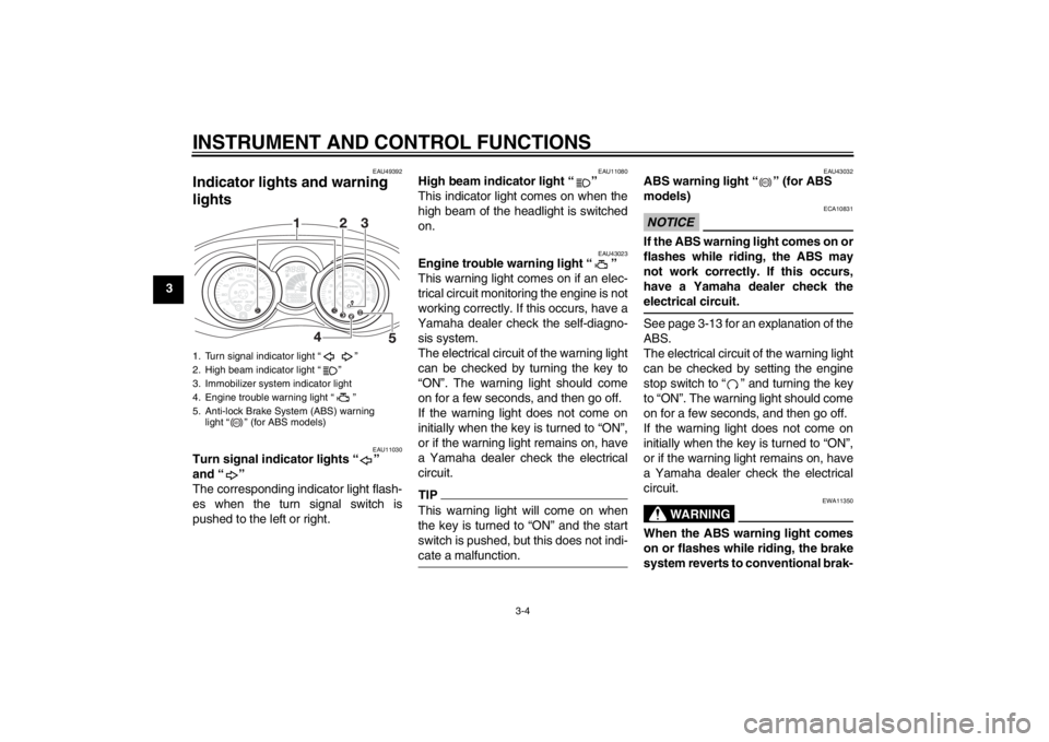
1. Turn signal indicator light “ ”
2. High beam indicator light “ ”
3. Immobilizer system indicator light
4. Engine trouble warning light “ ”
5. Anti-lock Brake System (ABS) warning
light “ ” (for ABS models)
ABS
ABS
U2ABE2E0.book Page 4 Thursday, August 30, 2012 2:36 PM
Page 26 of 96
INSTRUMENT AND CONTROL FUNCTIONS
3-8
3
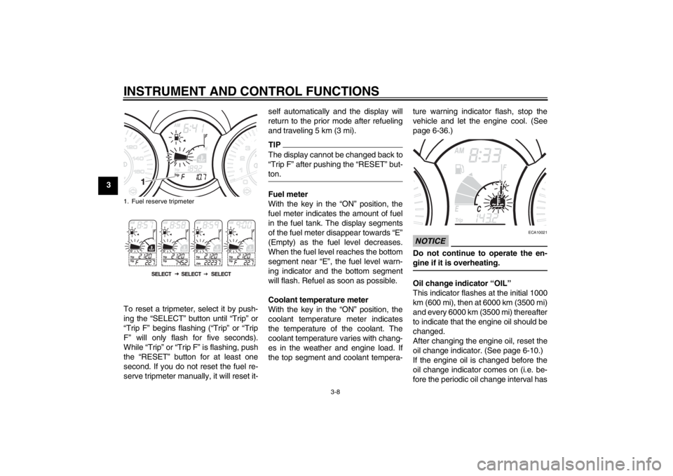
To reset a tripmeter, select it by push-
ing the “SELECT” button until “Trip” or
“Trip F” begins flashing (“Trip” or “Trip
F” will only flash for five seconds).
While “Trip” or “Trip F” is flashing, push
the “RESET” button for at least one
second. If you do not reset the fuel re-
serve tripmeter manually, it will reset it-self automatically and the display will
return to the prior mode after refueling
and traveling 5 km (3 mi).
TIPThe display cannot be changed back to
“Trip F” after pushing the “RESET” but-
ton.Fuel meter
With the key in the “ON” position, the
fuel meter indicates the amount of fuel
in the fuel tank. The display segments
of the fuel meter disappear towards “E”
(Empty) as the fuel level decreases.
When the fuel level reaches the bottom
segment near “E”, the fuel level warn-
ing indicator and the bottom segment
will flash. Refuel as soon as possible.
Coolant temperature meter
With the key in the “ON” position, the
coolant temperature meter indicates
the temperature of the coolant. The
coolant temperature varies with chang-
es in the weather and engine load. If
the top segment and coolant tempera-ture warning indicator flash, stop the
vehicle and let the engine cool. (See
page 6-36.)
NOTICE
ECA10021
Do not continue to operate the en-
gine if it is overheating.Oil change indicator “OIL”
This indicator flashes at the initial 1000
km (600 mi), then at 6000 km (3500 mi)
and every 6000 km (3500 mi) thereafter
to indicate that the engine oil should be
changed.
After changing the engine oil, reset the
oil change indicator. (See page 6-10.)
If the engine oil is changed before the
oil change indicator comes on (i.e. be-
fore the periodic oil change interval has
1. Fuel reserve tripmeterU2ABE2E0.book Page 8 Thursday, August 30, 2012 2:36 PM
Page 27 of 96
INSTRUMENT AND CONTROL FUNCTIONS
3-9
3 been reached), the indicator must be
reset after the oil change for the next
periodic oil change to be indicated at
the correct time. (See page 6-10.)
The electrical circuit of the indicator can
be checked according to the following
procedure.
1. Turn the key to “ON”.
2. Check that the indicator comes on
for a few seconds and then goes
off.
3. If the indicator does not come on,
have a Yamaha dealer check the
electrical circuit.
V-belt replacement indicator “V-
BELT”
This indicator flashes every 18000 km
(10500 mi) when the V-belt needs to be
replaced.
The electrical circuit of the indicator can
be checked according to the following
procedure.
1. Turn the key to “ON”.
2. Check that the indicator comes on
for a few seconds and then goes
off.3. If the indicator does not come on,
have a Yamaha dealer check the
electrical circuit.
Self-diagnosis device
This model is equipped with a self-diag-
nosis device for various electrical cir-
cuits.
If a problem is detected in any of those
circuits, the multi-function display will
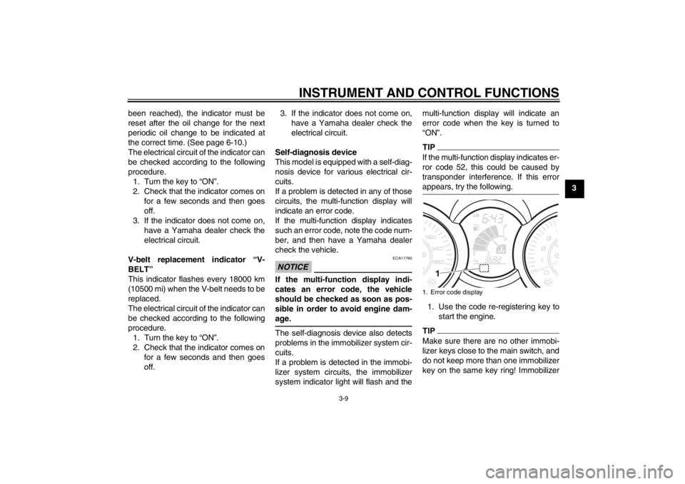
indicate an error code.
If the multi-function display indicates
such an error code, note the code num-
ber, and then have a Yamaha dealer
check the vehicle.
NOTICE
ECA11790
If the multi-function display indi-
cates an error code, the vehicle
should be checked as soon as pos-
sible in order to avoid engine dam-
age.The self-diagnosis device also detects
problems in the immobilizer system cir-
cuits.
If a problem is detected in the immobi-
lizer system circuits, the immobilizer
system indicator light will flash and themulti-function display will indicate an
error code when the key is turned to
“ON”.
TIPIf the multi-function display indicates er-
ror code 52, this could be caused by
transponder interference. If this error
appears, try the following.1. Use the code re-registering key to
start the engine.TIPMake sure there are no other immobi-
lizer keys close to the main switch, and
do not keep more than one immobilizer
key on the same key ring! Immobilizer1. Error code display
U2ABE2E0.book Page 9 Thursday, August 30, 2012 2:36 PM
Page 28 of 96
INSTRUMENT AND CONTROL FUNCTIONS
3-10
3system keys may cause signal interfer-
ence, which may prevent the engine
from starting.
2. If the engine starts, turn it off, and
try starting the engine with the
standard keys.
3. If one or both of the standard keys
do not start the engine, take the
vehicle, the code re-registering
key and both standard keys to a
Yamaha dealer and have the stan-
dard keys re-registered.
If the multi-function display indicates
any error codes, note the code number,
and then have a Yamaha dealer check
the vehicle.
Clock mode
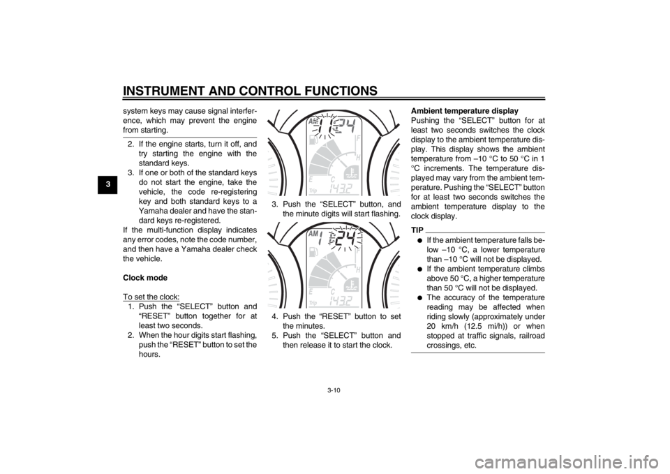
To set the clock:1. Push the “SELECT” button and
“RESET” button together for at
least two seconds.
2. When the hour digits start flashing,
push the “RESET” button to set the
hours.3. Push the “SELECT” button, and
the minute digits will start flashing.
4. Push the “RESET” button to set
the minutes.
5. Push the “SELECT” button and
then release it to start the clock.Ambient temperature display
Pushing the “SELECT” button for at
least two seconds switches the clock
display to the ambient temperature dis-
play. This display shows the ambient
temperature from –10 °C to 50 °C in 1
°C increments. The temperature dis-
played may vary from the ambient tem-
perature. Pushing the “SELECT” button
for at least two seconds switches the
ambient temperature display to the
clock display.
TIP●
If the ambient temperature falls be-
low –10 °C, a lower temperature
than –10 °C will not be displayed.
●
If the ambient temperature climbs
above 50 °C, a higher temperature
than 50 °C will not be displayed.
●
The accuracy of the temperature
reading may be affected when
riding slowly (approximately under
20 km/h (12.5 mi/h)) or when
stopped at traffic signals, railroad
crossings, etc.
U2ABE2E0.book Page 10 Thursday, August 30, 2012 2:36 PM
Page 31 of 96
INSTRUMENT AND CONTROL FUNCTIONS
3-13
3
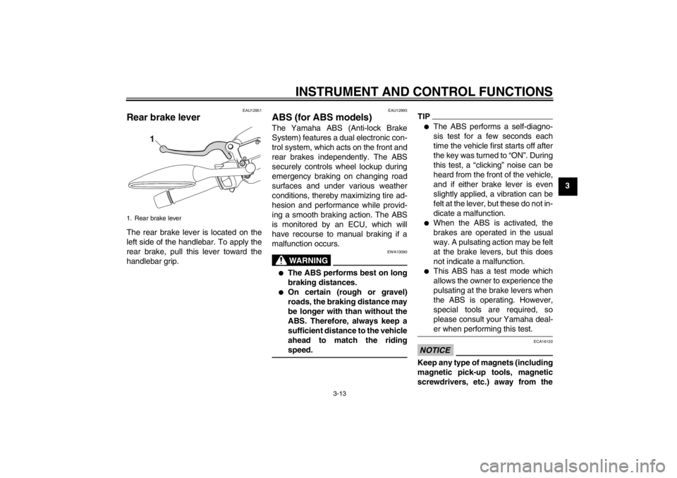
EAU12951
Rear brake lever The rear brake lever is located on the
left side of the handlebar. To apply the
rear brake, pull this lever toward the
handlebar grip.
EAU12995
ABS (for ABS models) The Yamaha ABS (Anti-lock Brake
System) features a dual electronic con-
trol system, which acts on the front and
rear brakes independently. The ABS
securely controls wheel lockup during
emergency braking on changing road
surfaces and under various weather
conditions, thereby maximizing tire ad-
hesion and performance while provid-
ing a smooth braking action. The ABS
is monitored by an ECU, which will
have recourse to manual braking if a
malfunction occurs.
WARNING
EWA10090
●
The ABS performs best on long
braking distances.
●
On certain (rough or gravel)
roads, the braking distance may
be longer with than without the
ABS. Therefore, always keep a
sufficient distance to the vehicle
ahead to match the riding
speed.
TIP●
The ABS performs a self-diagno-
sis test for a few seconds each
time the vehicle first starts off after
the key was turned to “ON”. During
this test, a “clicking” noise can be
heard from the front of the vehicle,
and if either brake lever is even
slightly applied, a vibration can be
felt at the lever, but these do not in-
dicate a malfunction.
●
When the ABS is activated, the
brakes are operated in the usual
way. A pulsating action may be felt
at the brake levers, but this does
not indicate a malfunction.
●
This ABS has a test mode which
allows the owner to experience the
pulsating at the brake levers when
the ABS is operating. However,
special tools are required, so
please consult your Yamaha deal-
er when performing this test.
NOTICE
ECA16120
Keep any type of magnets (including
magnetic pick-up tools, magnetic
screwdrivers, etc.) away from the
1. Rear brake lever
U2ABE2E0.book Page 13 Thursday, August 30, 2012 2:36 PM
Page 44 of 96
OPERATION AND IMPORTANT RIDING POINTS
5-1
5
EAU15951
Read the Owner’s Manual carefully to
become familiar with all controls. If
there is a control or function you do not
understand, ask your Yamaha dealer.
WARNING
EWA10271
Failure to familiarize yourself with
the controls can lead to loss of con-
trol, which could cause an accident
or injury.
EAU48020
TIPThis model is equipped with a lean an-
gle sensor to stop the engine in case of
a turnover. In this case, the multi-func-
tion display indicates error code 30, but
this is not a malfunction. Turn the key to
“OFF” and then to “ON” to clear the er-
ror code. Failing to do so will prevent
the engine from starting even though
the engine will crank when pushing the
start switch.
EAUS1892
Starting the engine NOTICE
ECA10250
See page 5-4 for engine break-in in-
structions prior to operating the ve-
hicle for the first time.In order for the ignition circuit cut-off
system to enable starting, the side-
stand must be up.
See page 3-21 for more information.
1. Turn the key to “ON”.
The following warning light, indica-
tor light and indicators should
come on for a few seconds, then
go off.
●
Engine trouble warning light
●
ABS warning light (for ABS
models)
●
Immobilizer system indicator
light
●
V-belt replacement indicator
●
Oil change indicator
U2ABE2E0.book Page 1 Thursday, August 30, 2012 2:36 PM
Page 89 of 96
SPECIFICATIONS
8-1
8
Dimensions:Overall length:
YP125R 2201 mm (86.7 in)
YP125RA 2201 mm (86.7 in)
YP125R Sport 2201 mm (86.7 in)
YP125RA Business 2370 mm (93.3 in)
Overall width:
776 mm (30.6 in)
Overall height:
YP125R 1214 mm (47.8 in)
YP125RA 1337 mm (52.6 in)
YP125R Sport 1337 mm (52.6 in)
YP125RA Business 1387 mm (54.6 in)
Seat height:
792 mm (31.2 in)
Wheelbase:
1535 mm (60.4 in)
Ground clearance:
135 mm (5.31 in)
Minimum turning radius:
1805 mm (71.1 in)Weight:Curb weight:
YP125R 174 kg (385 lb)
YP125RA 183 kg (403 lb)Engine:Engine type:
Liquid cooled 4-stroke, SOHC
Cylinder arrangement:
Single cylinder
Displacement:
124 cm³
Bore × stroke:
52.0 × 58.6 mm (2.05 × 2.31 in)Compression ratio:
11.20 : 1
Starting system:
Electric starter
Lubrication system:
Wet sump
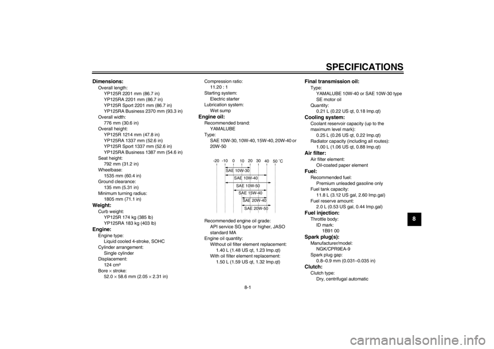
Engine oil:Recommended brand:
YAMALUBE
Type:
SAE 10W-30, 10W-40, 15W-40, 20W-40 or
20W-50
Recommended engine oil grade:
API service SG type or higher, JASO
standard MA
Engine oil quantity:
Without oil filter element replacement:
1.40 L (1.48 US qt, 1.23 Imp.qt)
With oil filter element replacement:
1.50 L (1.59 US qt, 1.32 Imp.qt)
Final transmission oil:Type:
YAMALUBE 10W-40 or SAE 10W-30 type
SE motor oil
Quantity:
0.21 L (0.22 US qt, 0.18 Imp.qt)Cooling system:Coolant reservoir capacity (up to the
maximum level mark):
0.25 L (0.26 US qt, 0.22 Imp.qt)
Radiator capacity (including all routes):
1.00 L (1.06 US qt, 0.88 Imp.qt)Air filter:Air filter element:
Oil-coated paper elementFuel:Recommended fuel:
Premium unleaded gasoline only
Fuel tank capacity:
11.8 L (3.12 US gal, 2.60 Imp.gal)
Fuel reserve amount:
2.0 L (0.53 US gal, 0.44 Imp.gal)Fuel injection:Throttle body:
ID mark:
1B91 00Spark plug(s):Manufacturer/model:
NGK/CPR9EA-9
Spark plug gap:
0.8–0.9 mm (0.031–0.035 in)Clutch:Clutch type:
Dry, centrifugal automatic
-20 -10 0
10 20 30
40
50 ˚C
SAE 10W-30
SAE 15W-40SAE 20W-40SAE 20W-50
SAE 10W-40SAE 10W-50
U2ABE2E0.book Page 1 Thursday, August 30, 2012 2:36 PM
Page 90 of 96

SPECIFICATIONS
8-2
8
Transmission:Primary reduction ratio:
(1.000)
Final drive:
Gear
Secondary reduction ratio:
41/14 × 44/13 (9.912)
Transmission type:
V-belt automaticChassis:Frame type:
Underbone
Caster angle:
28.00 °
Trail:
100 mm (3.9 in)Front tire:Type:
Tubeless
Size:
120/70-15 M/C 56P(PIRELLI-
METZELER)-56S(MICHELIN)
Manufacturer/model:
PIRELLI / GTS23
Manufacturer/model:
MICHELIN / GOLD STANDARD
Manufacturer/model:
MICHELIN / CITYGRIP
Manufacturer/model:
METZELER / FEELFREERear tire:Type:
TubelessSize:
140/70-14 M/C 68P(PIRELLI-
METZELER)-68S(MICHELIN)
Manufacturer/model:
PIRELLI / GTS24
Manufacturer/model:
MICHELIN / GOLD STANDARD
Manufacturer/model:
MICHELIN / CITYGRIP
Manufacturer/model:
METZELER / FEELFREE
Loading:Maximum load:
YP125R 180 kg (398 lb)
YP125RA 172 kg (379 lb)
(Total weight of rider, passenger, cargo and
accessories)Tire air pressure (measured on cold
tires):Loading condition:
0–90 kg (0–198 lb)
Front:
190 kPa (1.90 kgf/cm², 28 psi)
Rear:
220 kPa (2.20 kgf/cm², 32 psi)
Loading condition:
YP125R 90–180 kg (198–398 lb)
YP125RA 90–172 kg (198–379 lb)
Front:
210 kPa (2.10 kgf/cm², 30 psi)
Rear:
250 kPa (2.50 kgf/cm², 36 psi)
Front wheel:Wheel type:
Cast wheel
Rim size:
15 x MT3.5Rear wheel:Wheel type:
Cast wheel
Rim size:
14 x MT3.75Front brake:Type:
Single disc brake
Operation:
Right hand operation
Specified brake fluid:
DOT 4Rear brake:Type:
Single disc brake
Operation:
Left hand operation
Specified brake fluid:
DOT 4Front suspension:Type:
Telescopic fork
Spring/shock absorber type:
Coil spring/oil damper
Wheel travel:
110.0 mm (4.33 in)Rear suspension:Type:
Unit swing
U2ABE2E0.book Page 2 Thursday, August 30, 2012 2:36 PM
Page 92 of 96
CONSUMER INFORMATION
9-1
9
EAU48612
Identification numbers Record the vehicle identification num-
ber and model label information in the
spaces provided below for assistance
when ordering spare parts from a
Yamaha dealer or for reference in case
the vehicle is stolen.
VEHICLE IDENTIFICATION
NUMBER:
MODEL LABEL INFORMATION:
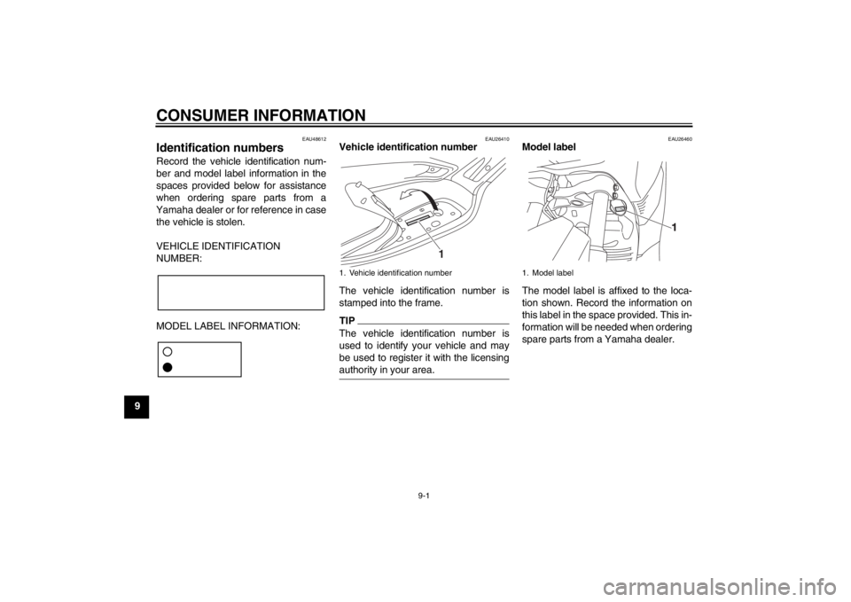
EAU26410
Vehicle identification number
The vehicle identification number is
stamped into the frame.TIPThe vehicle identification number is
used to identify your vehicle and may
be used to register it with the licensing
authority in your area.
EAU26460
Model label
The model label is affixed to the loca-
tion shown. Record the information on
this label in the space provided. This in-
formation will be needed when ordering
spare parts from a Yamaha dealer.
1. Vehicle identification number
1
1. Model label
U2ABE2E0.book Page 1 Thursday, August 30, 2012 2:36 PM