oil level YAMAHA XMAX 125 2013 Owners Manual
[x] Cancel search | Manufacturer: YAMAHA, Model Year: 2013, Model line: XMAX 125, Model: YAMAHA XMAX 125 2013Pages: 96, PDF Size: 4.83 MB
Page 6 of 96

TABLE OF CONTENTSSAFETY INFORMATION ..................1-1
Further safe-riding points ................1-5
DESCRIPTION ..................................2-1
Left view ..........................................2-1
Right view ........................................2-3
Controls and instruments.................2-5
INSTRUMENT AND CONTROL
FUNCTIONS.......................................3-1
Immobilizer system .........................3-1
Main switch/steering lock ................3-2
Indicator lights and
warning lights ..............................3-4
Speedometer ..................................3-5
Tachometer ....................................3-6
Multi-function display ......................3-6
Anti-theft alarm (optional) .............3-11
Handlebar switches ......................3-11
Front brake lever ..........................3-12
Rear brake lever ...........................3-13
ABS (for ABS models) ..................3-13
Fuel tank cap ................................3-14
Fuel ...............................................3-15
Catalytic converters ......................3-16
Securing bracket ...........................3-17
Seat ..............................................3-17
Storage compartments .................3-18
Travel trunk ..................................3-19
Adjusting the shock absorber
assemblies ................................3-20Sidestand ..................................... 3-21
Ignition circuit cut-off system ........ 3-21
Auxiliary DC jack .......................... 3-23
FOR YOUR SAFETY –
PRE-OPERATION CHECKS............. 4-1
OPERATION AND IMPORTANT
RIDING POINTS................................. 5-1
Starting the engine ......................... 5-1
Starting off ...................................... 5-2
Acceleration and deceleration ........ 5-3
Braking ........................................... 5-3
Tips for reducing fuel
consumption ............................... 5-4
Engine break-in .............................. 5-4
Parking ........................................... 5-5
PERIODIC MAINTENANCE AND
ADJUSTMENT................................... 6-1
Owner’s tool kit ............................... 6-2
Periodic maintenance chart for the
emission control system ............. 6-3
General maintenance and
lubrication chart .......................... 6-4
Removing and installing
the cowling and panel ................. 6-8
Checking the spark plug ................. 6-9
Engine oil ..................................... 6-10
Final transmission oil .................... 6-13
Coolant ......................................... 6-14Air filter and V-belt case air filter
elements ................................... 6-16
Adjusting the throttle grip free
play ........................................... 6-17
Valve clearance ........................... 6-18
Tires ............................................. 6-18
Cast wheels ................................. 6-20
Checking the front and
rear brake lever free play ......... 6-21
Checking the front and
rear brake pads ........................ 6-21
Checking the brake fluid level ...... 6-22
Changing the brake fluid .............. 6-24
Checking and lubricating
the cables ................................. 6-24
Checking and lubricating
the throttle grip and cable ......... 6-24
Lubricating the front and
rear brake levers ...................... 6-25
Checking and lubricating the
centerstand and sidestand ....... 6-25
Checking the front fork ................. 6-26
Checking the steering .................. 6-27
Checking the wheel bearings ....... 6-27
Battery ......................................... 6-27
Replacing the fuses ..................... 6-29
Replacing a headlight bulb .......... 6-30
Replacing a front turn signal light
bulb ........................................... 6-31
Replacing a tail/brake light bulb or
a rear turn signal light bulb ....... 6-31U2ABE2E0.book Page 1 Thursday, August 30, 2012 2:36 PM
Page 16 of 96
DESCRIPTION
2-3
2
EAU32230
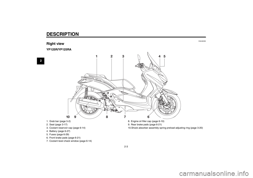
Right viewYP125R/YP125RA1. Grab bar (page 5-2)
2. Seat (page 3-17)
3. Coolant reservoir cap (page 6-14)
4. Battery (page 6-27)
5. Fuses (page 6-29)
6. Front brake pads (page 6-21)
7. Coolant level check window (page 6-14)8. Engine oil filler cap (page 6-10)
9. Rear brake pads (page 6-21)
10.Shock absorber assembly spring preload adjusting ring (page 3-20)U2ABE2E0.book Page 3 Thursday, August 30, 2012 2:36 PM
Page 17 of 96
DESCRIPTION
2-4
2 YP125RA Business Edition / YP125R Sports
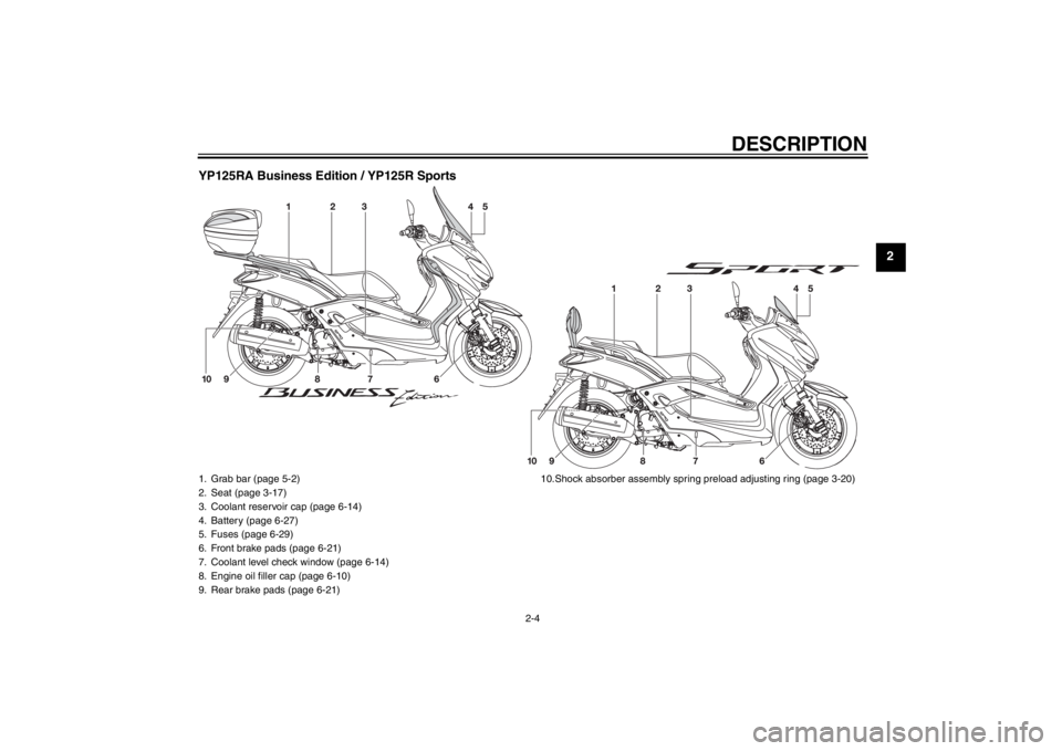
1. Grab bar (page 5-2)
2. Seat (page 3-17)
3. Coolant reservoir cap (page 6-14)
4. Battery (page 6-27)
5. Fuses (page 6-29)
6. Front brake pads (page 6-21)
7. Coolant level check window (page 6-14)
8. Engine oil filler cap (page 6-10)
9. Rear brake pads (page 6-21)10.Shock absorber assembly spring preload adjusting ring (page 3-20)
U2ABE2E0.book Page 4 Thursday, August 30, 2012 2:36 PM
Page 25 of 96
INSTRUMENT AND CONTROL FUNCTIONS
3-7
3
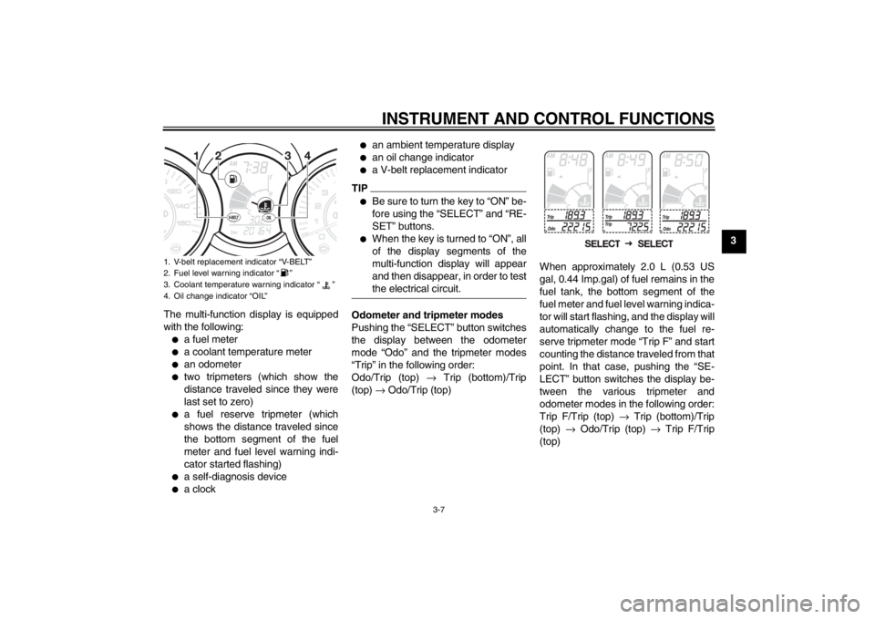
The multi-function display is equipped
with the following:
●
a fuel meter
●
a coolant temperature meter
●
an odometer
●
two tripmeters (which show the
distance traveled since they were
last set to zero)
●
a fuel reserve tripmeter (which
shows the distance traveled since
the bottom segment of the fuel
meter and fuel level warning indi-
cator started flashing)
●
a self-diagnosis device
●
a clock
●
an ambient temperature display
●
an oil change indicator
●
a V-belt replacement indicator
TIP●
Be sure to turn the key to “ON” be-
fore using the “SELECT” and “RE-
SET” buttons.
●
When the key is turned to “ON”, all
of the display segments of the
multi-function display will appear
and then disappear, in order to test
the electrical circuit.
Odometer and tripmeter modes
Pushing the “SELECT” button switches
the display between the odometer
mode “Odo” and the tripmeter modes
“Trip” in the following order:
Odo/Trip (top) → Trip (bottom)/Trip
(top) → Odo/Trip (top)When approximately 2.0 L (0.53 US
gal, 0.44 Imp.gal) of fuel remains in the
fuel tank, the bottom segment of the
fuel meter and fuel level warning indica-
tor will start flashing, and the display will
automatically change to the fuel re-
serve tripmeter mode “Trip F” and start
counting the distance traveled from that
point. In that case, pushing the “SE-
LECT” button switches the display be-
tween the various tripmeter and
odometer modes in the following order:
Trip F/Trip (top) → Trip (bottom)/Trip
(top) → Odo/Trip (top) → Trip F/Trip
(top)
1. V-belt replacement indicator “V-BELT”
2. Fuel level warning indicator “ ”
3. Coolant temperature warning indicator “ ”
4. Oil change indicator “OIL”
U2ABE2E0.book Page 7 Thursday, August 30, 2012 2:36 PM
Page 26 of 96
INSTRUMENT AND CONTROL FUNCTIONS
3-8
3
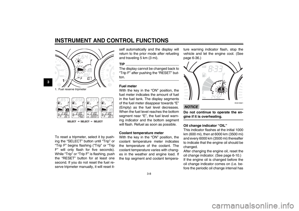
To reset a tripmeter, select it by push-
ing the “SELECT” button until “Trip” or
“Trip F” begins flashing (“Trip” or “Trip
F” will only flash for five seconds).
While “Trip” or “Trip F” is flashing, push
the “RESET” button for at least one
second. If you do not reset the fuel re-
serve tripmeter manually, it will reset it-self automatically and the display will
return to the prior mode after refueling
and traveling 5 km (3 mi).
TIPThe display cannot be changed back to
“Trip F” after pushing the “RESET” but-
ton.Fuel meter
With the key in the “ON” position, the
fuel meter indicates the amount of fuel
in the fuel tank. The display segments
of the fuel meter disappear towards “E”
(Empty) as the fuel level decreases.
When the fuel level reaches the bottom
segment near “E”, the fuel level warn-
ing indicator and the bottom segment
will flash. Refuel as soon as possible.
Coolant temperature meter
With the key in the “ON” position, the
coolant temperature meter indicates
the temperature of the coolant. The
coolant temperature varies with chang-
es in the weather and engine load. If
the top segment and coolant tempera-ture warning indicator flash, stop the
vehicle and let the engine cool. (See
page 6-36.)
NOTICE
ECA10021
Do not continue to operate the en-
gine if it is overheating.Oil change indicator “OIL”
This indicator flashes at the initial 1000
km (600 mi), then at 6000 km (3500 mi)
and every 6000 km (3500 mi) thereafter
to indicate that the engine oil should be
changed.
After changing the engine oil, reset the
oil change indicator. (See page 6-10.)
If the engine oil is changed before the
oil change indicator comes on (i.e. be-
fore the periodic oil change interval has
1. Fuel reserve tripmeterU2ABE2E0.book Page 8 Thursday, August 30, 2012 2:36 PM
Page 42 of 96
FOR YOUR SAFETY – PRE-OPERATION CHECKS
4-1
4
EAU15597
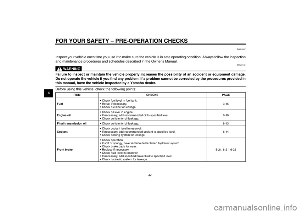
Inspect your vehicle each time you use it to make sure the vehicle is in safe operating condition. Always follow the inspection
and maintenance procedures and schedules described in the Owner’s Manual.
WARNING
EWA11151
Failure to inspect or maintain the vehicle properly increases the possibility of an accident or equipment damage.
Do not operate the vehicle if you find any problem. If a problem cannot be corrected by the procedures provided in
this manual, have the vehicle inspected by a Yamaha dealer.Before using this vehicle, check the following points:
ITEM CHECKS PAGE
Fuel Check fuel level in fuel tank.
Refuel if necessary.
Check fuel line for leakage.3-15
Engine oil Check oil level in engine.
If necessary, add recommended oil to specified level.
Check vehicle for oil leakage.6-10
Final transmission oil Check vehicle for oil leakage. 6-13
Coolant Check coolant level in reservoir.
If necessary, add recommended coolant to specified level.
Check cooling system for leakage.6-14
Front brake Check operation.
If soft or spongy, have Yamaha dealer bleed hydraulic system.
Check brake pads for wear.
Replace if necessary.
Check fluid level in reservoir.
If necessary, add specified brake fluid to specified level.
Check hydraulic system for leakage.6-21, 6-21, 6-22
U2ABE2E0.book Page 1 Thursday, August 30, 2012 2:36 PM
Page 53 of 96

PERIODIC MAINTENANCE AND ADJUSTMENT
6-5
6
10*Steering bearings Check bearing play and steering
for roughness.√√√√√
Lubricate with lithium-soap-based
grease.Every 24000 km (14000 mi)
11*Chassis fasteners Make sure that all nuts, bolts and
screws are properly tightened.√√√√√
12Front brake lever
pivot shaft Lubricate with silicone grease.√√√√√
13Rear brake lever
pivot shaft Lubricate with silicone grease.√√√√√
14Sidestand, center-
stand Check operation.
Lubricate with lithium-soap-based
grease.√√√√√
15*Sidestand switch Check operation.√√√√√√
16*Front fork Check operation and for oil leak-
age.√√√√
17*Shock absorber as-
semblies Check operation and shock ab-
sorbers for oil leakage.√√√√
18 Engine oil Change. (See pages 3-6 and
6-10.)√When the oil change indicator flashes [5000 km (3000 mi) after
the initial 1000 km (600 mi) and every 6000 km (3500 mi) thereaf-
ter]
Check oil level and vehicle for oil
leakage.Every 3000 km (1800 mi)√
19Engine oil filter ele-
ment Replace.√√√ NO. ITEM CHECK OR MAINTENANCE JOBODOMETER READING
ANNUAL
CHECK 1000 km
(600 mi)6000 km
(3500 mi)12000 km
(7000 mi)18000 km
(10500 mi)24000 km
(14000 mi)
U2ABE2E0.book Page 5 Thursday, August 30, 2012 2:36 PM
Page 54 of 96
PERIODIC MAINTENANCE AND ADJUSTMENT
6-6
6
EAU38262
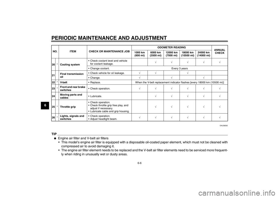
TIP●
Engine air filter and V-belt air filters
This model’s engine air filter is equipped with a disposable oil-coated paper element, which must not be cleaned with
compressed air to avoid damaging it.
The engine air filter element needs to be replaced and the V-belt air filter elements need to be serviced more frequent-
ly when riding in unusually wet or dusty areas.
20*Cooling system Check coolant level and vehicle
for coolant leakage.√√√√√
Change coolant. Every 3 years
21Final transmission
oil Check vehicle for oil leakage.√√ √
Change.√√√
22*V- b e l t Replace. When the V-belt replacement indicator flashes [every 18000 km (10500 mi)]
23*Front and rear brake
switches Check operation.√√√√√√
24Moving parts and
cables Lubricate.√√√√√
25*Throttle grip Check operation.
Check throttle grip free play, and
adjust if necessary.
Lubricate cable and grip housing.√√√√√
26*Lights, signals and
switches Check operation.
Adjust headlight beam.√√√√√√ NO. ITEM CHECK OR MAINTENANCE JOBODOMETER READING
ANNUAL
CHECK 1000 km
(600 mi)6000 km
(3500 mi)12000 km
(7000 mi)18000 km
(10500 mi)24000 km
(14000 mi)U2ABE2E0.book Page 6 Thursday, August 30, 2012 2:36 PM
Page 58 of 96
PERIODIC MAINTENANCE AND ADJUSTMENT
6-10
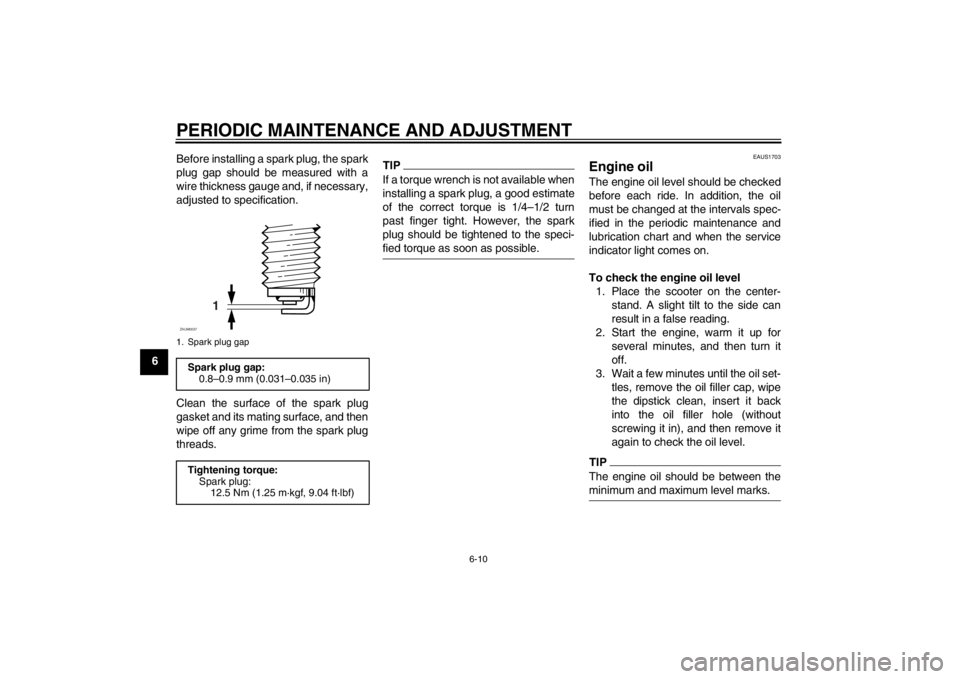
6Before installing a spark plug, the spark
plug gap should be measured with a
wire thickness gauge and, if necessary,
adjusted to specification.
Clean the surface of the spark plug
gasket and its mating surface, and then
wipe off any grime from the spark plug
threads.
TIPIf a torque wrench is not available when
installing a spark plug, a good estimate
of the correct torque is 1/4–1/2 turn
past finger tight. However, the spark
plug should be tightened to the speci-
fied torque as soon as possible.
EAUS1703
Engine oil The engine oil level should be checked
before each ride. In addition, the oil
must be changed at the intervals spec-
ified in the periodic maintenance and
lubrication chart and when the service
indicator light comes on.
To check the engine oil level
1. Place the scooter on the center-
stand. A slight tilt to the side can
result in a false reading.
2. Start the engine, warm it up for
several minutes, and then turn it
off.
3. Wait a few minutes until the oil set-
tles, remove the oil filler cap, wipe
the dipstick clean, insert it back
into the oil filler hole (without
screwing it in), and then remove it
again to check the oil level.TIPThe engine oil should be between the
minimum and maximum level marks.
1. Spark plug gapSpark plug gap:
0.8–0.9 mm (0.031–0.035 in)
Tightening torque:
Spark plug:
12.5 Nm (1.25 m·kgf, 9.04 ft·lbf)
1
ZAUM0037
U2ABE2E0.book Page 10 Thursday, August 30, 2012 2:36 PM
Page 59 of 96
PERIODIC MAINTENANCE AND ADJUSTMENT
6-11
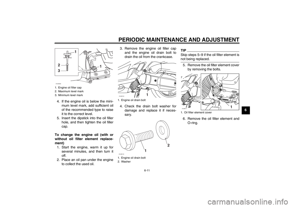
6 4. If the engine oil is below the mini-
mum level mark, add sufficient oil
of the recommended type to raise
it to the correct level.
5. Insert the dipstick into the oil filler
hole, and then tighten the oil filler
cap.
To change the engine oil (with or
without oil filter element replace-
ment)
1. Start the engine, warm it up for
several minutes, and then turn it
off.
2. Place an oil pan under the engine
to collect the used oil.3. Remove the engine oil filler cap
and the engine oil drain bolt to
drain the oil from the crankcase.
4. Check the drain bolt washer for
damage and replace it if neces-
sary.
TIPSkip steps 5–9 if the oil filter element is
not being replaced.5. Remove the oil filter element cover
by removing the bolts.
6. Remove the oil filter element and
O-ring.
1. Engine oil filler cap
2. Maximum level mark
3. Minimum level mark
1
32
1
ZAUM0685
1. Engine oil drain bolt
1. Engine oil drain bolt
2. WasherZAUM0702
11
2
ZAUM0129
1. Oil filter element coverZAUM0711
1
U2ABE2E0.book Page 11 Thursday, August 30, 2012 2:36 PM