engine coolant YAMAHA XMAX 125 2014 Owners Manual
[x] Cancel search | Manufacturer: YAMAHA, Model Year: 2014, Model line: XMAX 125, Model: YAMAHA XMAX 125 2014Pages: 94, PDF Size: 8.21 MB
Page 6 of 94

TABLE OF CONTENTSSAFETY INFORMATION.................. 1-1
Further safe-riding points ............... 1-5
DESCRIPTION.................................. 2-1
Left view ......................................... 2-1
Right view ....................................... 2-2
Controls and instruments ............... 2-3
INSTRUMENT AND CONTROL
FUNCTIONS...................................... 3-1
Immobilizer system......................... 3-1
Main switch/steering lock............... 3-2
Indicator lights and warning
lights............................................ 3-3
Multi-function meter unit ................ 3-5
Anti-theft alarm (optional) ............. 3-13
Handlebar switches ...................... 3-14
Front brake lever .......................... 3-15
Rear brake lever ........................... 3-15
ABS (for ABS models) .................. 3-16
Fuel tank cap ................................ 3-17
Fuel ............................................... 3-17
Catalytic converters...................... 3-19
Seat .............................................. 3-19
Storage compartments................. 3-20
Adjusting the shock absorber
assemblies ................................ 3-21
Sidestand ..................................... 3-22
Ignition circuit cut-off system ....... 3-23FOR YOUR SAFETY –
PRE-OPERATION CHECKS............. 4-1
OPERATION AND IMPORTANT
RIDING POINTS................................ 5-1
Starting the engine .......................... 5-1
Starting off ...................................... 5-2
Acceleration and deceleration ........ 5-3
Braking ............................................ 5-3
Tips for reducing fuel
consumption ................................ 5-4
Engine break-in ............................... 5-4
Parking ............................................ 5-5
PERIODIC MAINTENANCE AND
ADJUSTMENT................................... 6-1
Owner’s tool kit ............................... 6-2
Periodic maintenance chart for the
emission control system .............. 6-3
General maintenance and
lubrication chart ........................... 6-4
Removing and installing panels ...... 6-8
Checking the spark plug ............... 6-10
Engine oil....................................... 6-12
Final transmission oil..................... 6-14
Coolant.......................................... 6-15
Air filter and V-belt case air filter
elements and check hoses ........ 6-16
Checking the throttle grip free
play ............................................ 6-18
Valve clearance ............................. 6-18Tires .............................................. 6-18
Cast wheels .................................. 6-20
Checking the front and rear brake
lever free play ............................ 6-21
Checking the front and rear brake
pads .......................................... 6-21
Checking the brake fluid level ...... 6-22
Changing the brake fluid .............. 6-24
Checking and lubricating the
cables ........................................ 6-24
Checking and lubricating the
throttle grip and cable ............... 6-24
Lubricating the front and rear
brake levers ............................... 6-25
Checking and lubricating the
centerstand and sidestand........ 6-25
Checking the front fork ................. 6-26
Checking the steering................... 6-27
Checking the wheel bearings ....... 6-27
Battery .......................................... 6-27
Replacing the fuses ...................... 6-29
Replacing a headlight bulb ........... 6-30
Tail/brake light .............................. 6-31
Front turn signal light .................... 6-31
Replacing a rear turn signal light
bulb ........................................... 6-31
Replacing the license plate light
bulb ........................................... 6-32
Auxiliary light ................................ 6-33
Troubleshooting............................ 6-33
Troubleshooting charts................. 6-34U2DME1E0.book Page 1 Wednesday, October 23, 2013 1:37 PM
Page 14 of 94
DESCRIPTION
2-1
2
EAU10411
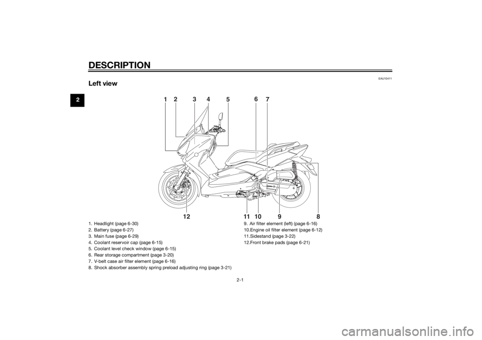
Left view
1
5
2
4
3
7 6
98 10 11
12
1. Headlight (page 6-30)
2. Battery (page 6-27)
3. Main fuse (page 6-29)
4. Coolant reservoir cap (page 6-15)
5. Coolant level check window (page 6-15)
6. Rear storage compartment (page 3-20)
7. V-belt case air filter element (page 6-16)
8. Shock absorber assembly spring preload adjusting ring (page 3-21)9. Air filter element (left) (page 6-16)
10.Engine oil filter element (page 6-12)
11.Sidestand (page 3-22)
12.Front brake pads (page 6-21)U2DME1E0.book Page 1 Wednesday, October 23, 2013 1:37 PM
Page 21 of 94
INSTRUMENT AND CONTROL FUNCTIONS
3-5
3
TIPThe ABS warning light may come on
while accelerating the engine with the
scooter on its centerstand, but this
does not indicate a malfunction.
EAU26878
Immobilizer system indicator
light “ ”
The electrical circuit of the indicator
light can be checked by turning the key
to “ON”. The indicator light should
come on for a few seconds, and then
go off.
If the indicator light does not come on
initially when the key is turned to “ON”,
or if the indicator light remains on, have
a Yamaha dealer check the electrical
circuit.
When the key is turned to “OFF” and
30 seconds have passed, the indicator
light will start flashing indicating the im-
mobilizer system is enabled. After 24
hours have passed, the indicator light
will stop flashing, however the immobi-
lizer system is still enabled.The self-diagnosis device also detects
problems in the immobilizer system
circuits. (See page 3-12 for an expla-
nation of the self-diagnosis device.)
EAUM3313
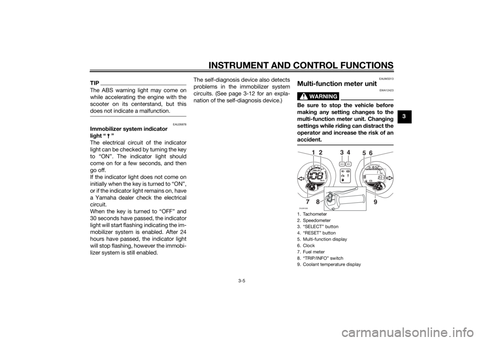
Multi-function meter unit
WARNING
EWA12423
Be sure to stop the vehicle before
making any setting changes to the
multi-function meter unit. Changing
settings while riding can distract the
operator and increase the risk of an
accident.1. Tachometer
2. Speedometer
3. “SELECT” button
4. “RESET” button
5. Multi-function display
6. Clock
7. Fuel meter
8. “TRIP/INFO” switch
9. Coolant temperature displayZAUM1099
3
987654321
11 10
12
0
1000r/minx
km/h
E
F
CHkm
Odo
AirA
veCo
ns
OilV- Be
lt
Ti
m
eTripOdo
SELECT
RESET
F
4
6
5
7
2
18
9
INFOTRIP
U2DME1E0.book Page 5 Wednesday, October 23, 2013 1:37 PM
Page 22 of 94
INSTRUMENT AND CONTROL FUNCTIONS
3-6
3The multi-function meter unit is
equipped with the following:
a speedometer
a tachometer
a fuel meter
a clock
an odometer and tripmeter display
a multi-function display
a coolant temperature meter
TIPBe sure to turn the key to “ON” be-
fore using the “Select”, “Reset”,
“TRIP” and “INFO” buttons.
When the key is turned to “ON”, all
display segments of the multi-
function meter unit will momen-
tarily appear in order to test the
electrical circuit. The speedome-
ter and odometer will then perform
a display check and a welcome
message will scroll across the
multi-function display.
For the UK, traveling speed, dis-
tance traveled, and fuel consump-
tion measurements can be
displayed in kilometer or mileage
based units. To switch between
miles and kilometers; hold the“SELECT” switch pushed, turn the
main switch to “ON”, and keep the
“SELECT” switch pushed for an
additional 8 seconds.
For other countries, traveling
speed, distance traveled and fuel
consumption measurements are
displayed in kilometer base units.
Speedometer
The speedometer shows the riding
speed.
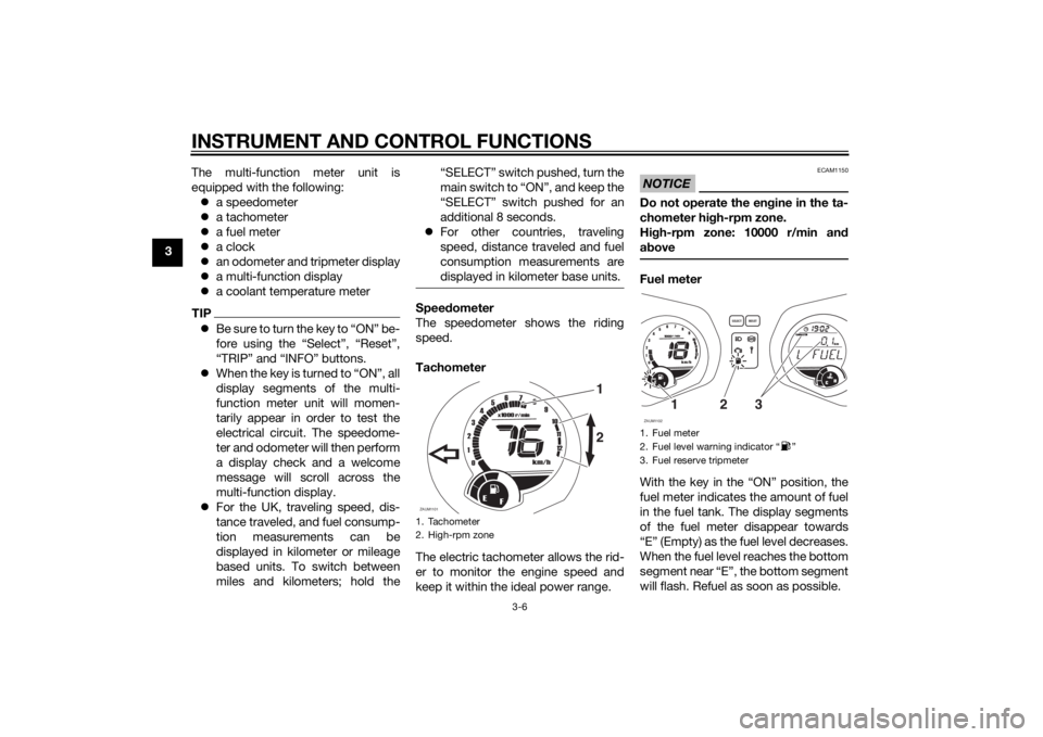
Tachometer
The electric tachometer allows the rid-
er to monitor the engine speed and
keep it within the ideal power range.
NOTICE
ECAM1150
Do not operate the engine in the ta-
chometer high-rpm zone.
High-rpm zone: 10000 r/min and
aboveFuel meter
With the key in the “ON” position, the
fuel meter indicates the amount of fuel
in the fuel tank. The display segments
of the fuel meter disappear towards
“E” (Empty) as the fuel level decreases.
When the fuel level reaches the bottom
segment near “E”, the bottom segment
will flash. Refuel as soon as possible.
1. Tachometer
2. High-rpm zoneZAUM1101
1
98
7
6
54321
11 10
12
0
1000
r/min
x
km/h
E
F
2
1. Fuel meter
2. Fuel level warning indicator Ž
3. Fuel reserve tripmeterZAUM1102
987654321
11 10
12
0
1000r/minkm/h
E
F
CHkm
T
ripOdo
SELECT
RESET
F
3
1
2
U2DME1E0.book Page 6 Wednesday, October 23, 2013 1:37 PM
Page 29 of 94
INSTRUMENT AND CONTROL FUNCTIONS
3-13
3 If the display indicates any error codes,
note the code number, and then have
a Yamaha dealer check the vehicle.
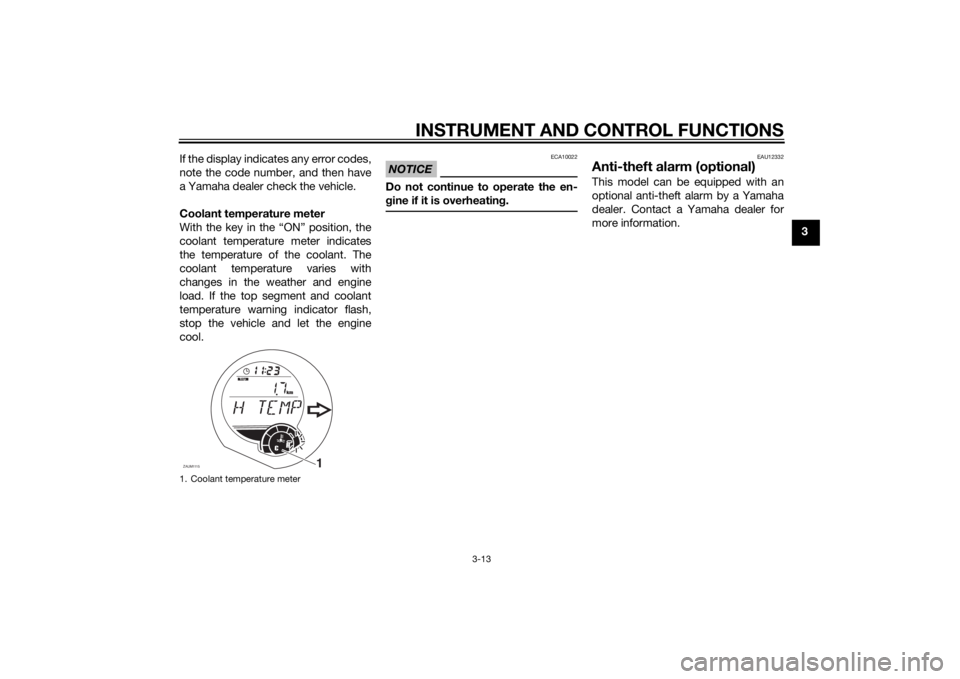
Coolant temperature meter
With the key in the “ON” position, the
coolant temperature meter indicates
the temperature of the coolant. The
coolant temperature varies with
changes in the weather and engine
load. If the top segment and coolant
temperature warning indicator flash,
stop the vehicle and let the engine
cool.
NOTICE
ECA10022
Do not continue to operate the en-
gine if it is overheating.
EAU12332
Anti-theft alarm (optional)This model can be equipped with an
optional anti-theft alarm by a Yamaha
dealer. Contact a Yamaha dealer for
more information.
1. Coolant temperature meterZAUM1115
1
CH
km
Trip
U2DME1E0.book Page 13 Wednesday, October 23, 2013 1:37 PM
Page 41 of 94
FOR YOUR SAFETY – PRE-OPERATION CHECKS
4-1
4
EAU15598
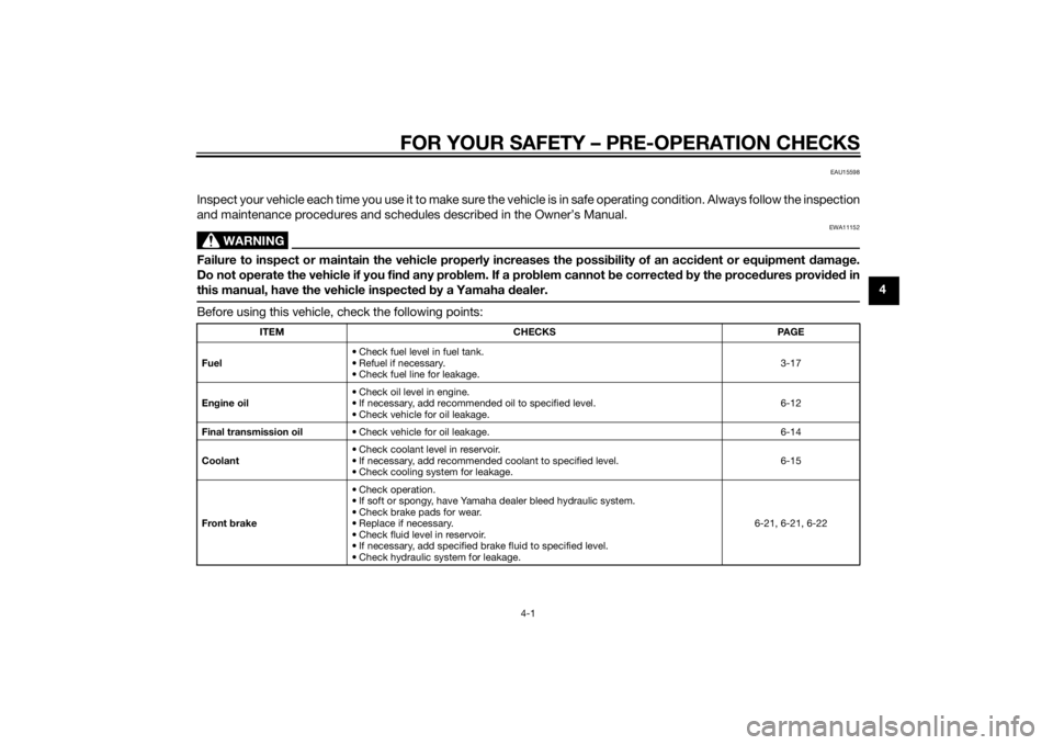
Inspect your vehicle each time you use it to make sure the vehicle is in safe operating condition. Always follow the inspection
and maintenance procedures and schedules described in the Owner’s Manual.
WARNING
EWA11152
Failure to inspect or maintain the vehicle properly increases the possibility of an accident or equipment damage.
Do not operate the vehicle if you find any problem. If a problem cannot be corrected by the procedures provided in
this manual, have the vehicle inspected by a Yamaha dealer.Before using this vehicle, check the following points:
ITEM CHECKS PAGE
Fuel• Check fuel level in fuel tank.
• Refuel if necessary.
• Check fuel line for leakage.3-17
Engine oil• Check oil level in engine.
• If necessary, add recommended oil to specified level.
• Check vehicle for oil leakage.6-12
Final transmission oil• Check vehicle for oil leakage. 6-14
Coolant• Check coolant level in reservoir.
• If necessary, add recommended coolant to specified level.
• Check cooling system for leakage.6-15
Front brake• Check operation.
• If soft or spongy, have Yamaha dealer bleed hydraulic system.
• Check brake pads for wear.
• Replace if necessary.
• Check fluid level in reservoir.
• If necessary, add specified brake fluid to specified level.
• Check hydraulic system for leakage.6-21, 6-21, 6-22
U2DME1E0.book Page 1 Wednesday, October 23, 2013 1:37 PM
Page 53 of 94
PERIODIC MAINTENANCE AND ADJUSTMENT
6-6
6
EAU38263
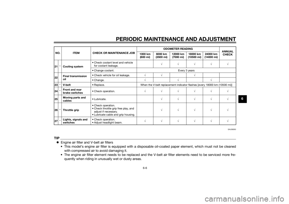
TIPEngine air filter and V-belt air filters
• This model’s engine air filter is equipped with a disposable oil-coated paper element, which must not be cleaned
with compressed air to avoid damaging it.
• The engine air filter element needs to be replaced and the V-belt air filter elements need to be serviced more fre-
quently when riding in unusually wet or dusty areas.21*Cooling system• Check coolant level and vehicle
for coolant leakage.√√√√√
• Change coolant. Every 3 years
22Final transmission
oil• Check vehicle for oil leakage.√√ √
• Change.√√√
23*V-belt• Replace. When the V-belt replacement indicator flashes [every 18000 km (10500 mi)]
24*Front and rear
brake switches• Check operation.√√√√√√
25Moving parts and
cables• Lubricate.√√√√√
26*Throttle grip• Check operation.
• Check throttle grip free play, and
adjust if necessary.
• Lubricate cable and grip housing.√√√√√
27*Lights, signals and
switches• Check operation.
• Adjust headlight beam.√√√√√√ NO. ITEM CHECK OR MAINTENANCE JOBODOMETER READING
ANNUAL
CHECK 1000 km
(600 mi)6000 km
(3500 mi)12000 km
(7000 mi)18000 km
(10500 mi)24000 km
(14000 mi)
U2DME1E0.book Page 6 Wednesday, October 23, 2013 1:37 PM
Page 62 of 94
PERIODIC MAINTENANCE AND ADJUSTMENT
6-15
66. Install the final transmission oil
drain bolt and its new gasket, and
then tighten the bolt to the speci-
fied torque.
7. Refill with the specified amount of
the recommended final transmis-
sion oil. WARNING! Make sure
that no foreign material enters
the final transmission case.
Make sure that no oil gets on
the tire or wheel.
[EWA11312]
8. Install the final transmission oil fill-
er cap and its new O-ring, and
then tighten the oil filler cap.
9. Check the final transmission case
for oil leakage. If oil is leaking,
check for the cause.
EAU20071
CoolantThe coolant level should be checked
before each ride. In addition, the cool-
ant must be changed at the intervals
specified in the periodic maintenance
and lubrication chart.
EAUM3043
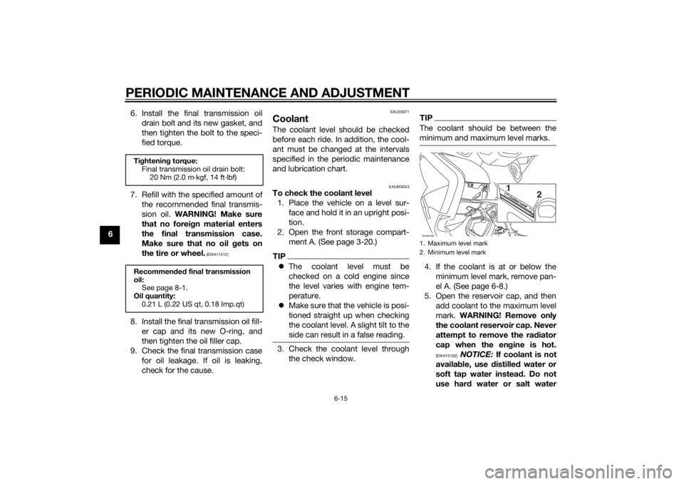
To check the coolant level
1. Place the vehicle on a level sur-
face and hold it in an upright posi-
tion.
2. Open the front storage compart-
ment A. (See page 3-20.)TIPThe coolant level must be
checked on a cold engine since
the level varies with engine tem-
perature.
Make sure that the vehicle is posi-
tioned straight up when checking
the coolant level. A slight tilt to the
side can result in a false reading.3. Check the coolant level through
the check window.
TIPThe coolant should be between the
minimum and maximum level marks.4. If the coolant is at or below the
minimum level mark, remove pan-
el A. (See page 6-8.)
5. Open the reservoir cap, and then
add coolant to the maximum level
mark. WARNING! Remove only
the coolant reservoir cap. Never
attempt to remove the radiator
cap when the engine is hot.
[EWA15162]
NOTICE: If coolant is not
available, use distilled water or
soft tap water instead. Do not
use hard water or salt water
Tightening torque:
Final transmission oil drain bolt:
20 Nm (2.0 m·kgf, 14 ft·lbf)
Recommended final transmission
oil:
See page 8-1.
Oil quantity:
0.21 L (0.22 US qt, 0.18 Imp.qt)
1. Maximum level mark
2. Minimum level markZAUM1029
2 1
Coolant LevelCoolant L
evelH
ighH
igh
LowLo
w
U2DME1E0.book Page 15 Wednesday, October 23, 2013 1:37 PM
Page 63 of 94
PERIODIC MAINTENANCE AND ADJUSTMENT
6-16
6 since it is harmful to the engine.
If water has been used instead
of coolant, replace it with cool-
ant as soon as possible, other-
wise the cooling system will not
be protected against frost and
corrosion. If water has been
added to the coolant, have a
Yamaha dealer check the anti-
freeze content of the coolant as
soon as possible, otherwise the
effectiveness of the coolant will
be reduced.
[ECA10473]
6. Close the reservoir cap, and then
install the panel.7. Close the front storage compart-
ment.
EAU33032
Changing the coolant
The coolant must be changed at the in-
tervals specified in the periodic main-
tenance and lubrication chart. Have a
Yamaha dealer change the coolant.
WARNING! Never attempt to remove
the radiator cap when the engine is
hot.
[EWA10382]EAUM3370
Air filter and V-belt case air fil-
ter elements and check hosesThe air filter element should be re-
placed and the V-belt case air filter el-
ement should be cleaned at the
intervals specified in the periodic main-
tenance and lubrication chart. Service
the air filter elements more frequently if
you are riding in unusually wet or dusty
areas.
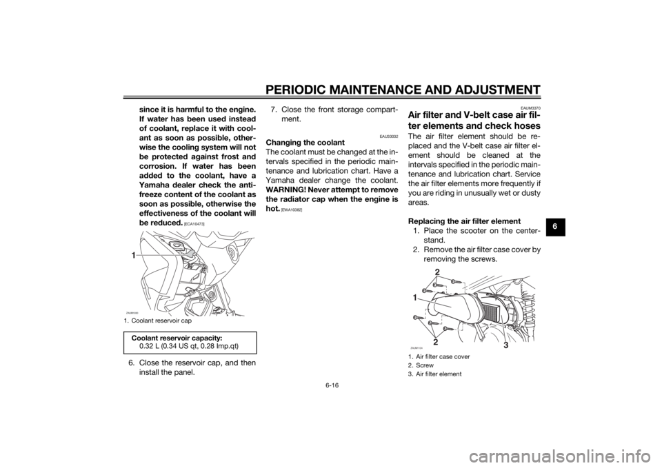
Replacing the air filter element
1. Place the scooter on the center-
stand.
2. Remove the air filter case cover by
removing the screws.
1. Coolant reservoir capCoolant reservoir capacity:
0.32 L (0.34 US qt, 0.28 Imp.qt)ZAUM10301
1. Air filter case cover
2. Screw
3. Air filter elementZAUM11241
22
3
U2DME1E0.book Page 16 Wednesday, October 23, 2013 1:37 PM
Page 82 of 94
PERIODIC MAINTENANCE AND ADJUSTMENT
6-35
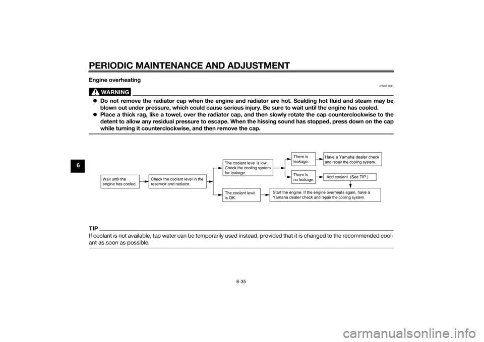
6Engine overheating
WARNING
EWAT1041
Do not remove the radiator cap when the engine and radiator are hot. Scalding hot fluid and steam may be
blown out under pressure, which could cause serious injury. Be sure to wait until the engine has cooled.
Place a thick rag, like a towel, over the radiator cap, and then slowly rotate the cap counterclockwise to the
detent to allow any residual pressure to escape. When the hissing sound has stopped, press down on the cap
while turning it counterclockwise, and then remove the cap.TIPIf coolant is not available, tap water can be temporarily used instead, provided that it is changed to the recommended cool-
ant as soon as possible.
Wait until the
engine has cooled.
Check the coolant level in the
reservoir and radiator.
The coolant level
is OK.The coolant level is low.
Check the cooling system
for leakage.
Have a Yamaha dealer checkand repair the cooling system.Add coolant. (See TIP.)
Start the engine. If the engine overheats again,
have a
Yamaha dealer check
and repair the cooling system.
There is
leakage.
There is
no leakage.
U2DME1E0.book Page 35 Wednesday, October 23, 2013 1:37 PM